


USER INSTRUCTIONS
Installation
Automax CENTURA™ CE Series |
Operation |
|
Electric Rotary Valve Actuator |
||
Maintenance |
||
|
||
FCD AXENIM0037-01 – 10/05 (Replaces AUTO-37) |
|
|
|
|
Experience In Motion

Introduction
The Centura electric actuator is a rotary valve actuator with output torques from 250 to 1,500 in-lbs. It has been designed for NEMA 4, 4X, 7, 9 and can come with a 4-20 mA card for modulating service.
Storage
For short and long term storage refer to short and long term storage conditions CE Actuator.
Maintenance
Centura Series actuators contain a permanently lubricated, precision cut, heat treated gear train for long, reliable cycle life. There is no need to change gear train grease; however, should it become necessary to refill, use a multi-purpose grease such as DuBois MPG-2.
Permanent split capacitor gearmotors have been equipped with thermal protectors. After many operations, especially in warm environments, the motor will heat up. To guard the motor against overheating, the thermal cut-out blocks power to the motor and maintains this state until the motor’s temperature drops to a satisfactory level. This thermal protection means that the actuator will not move when overheated. Consideration must be given to the duty cycle requirements of the actuator.
When replacing the cover, the machined joints must be clean and clear of any obstructions. The integrity of the explosion-proof rating depends on the care of these joints.
Installation
1.This section of the instruction sheet applies to the on-off units. For instructions on Modulating units, please see the ESP3 Electronic Servo Positioner Instructions.
2.Manually open and close valve to ensure freeness of operation.
a Caution: To prevent ignition of hazardous atmospheres, keep unit tight while circuits are alive. Disconnect supply circuit before opening.
3.Be sure valve and Automax actuator rotate in the same direction and are in the same position (i.e., valve closed, actuator closed). If not sure, electrically operate the actuator to determine its operating range, taking note of any explosion safety requirement. The electric actuators are factory set for 90 degree operation.
Automax CENTURA™ CE Series FCD AXENIM0037-01 – 12/05
aCaution: Use heavy duty brake option ‘K’ for rubber lined butterfly valves & dampers or applications that may back drive the unit.
4.Mount Automax actuator to valve with Automax provided mounting hardware to ensure proper alignment. Use mounting hardware that has 11/2 times bolt length engagement. (Do not use the manual
override to align actuator shaft to valve shaft, as this could drive the actuator out of its operating range).
NOTE: Some valves have manual stops; remove if appropriate or set actuator to operate within those travel stops).
5.Care should be taken to align valve stem properly with Automax actuator output shaft (misalignment will cause premature failure of assembly).
6.To connect power to terminal strip of actuator, remove the cover and locate the terminal wiring schematic inside the cover.
7.Connect power to terminal strip according to schematic diagram (power should be fused with a 5 amp slow-blow fuse). The actuator should be wired and grounded in accordance with Local and National Electrical Codes.
aCaution: Consult factory when wiring multiple actuators in series or parallel. Serious damage may result. User must isolate unused winding.
8.Before replacing cover, actuate valve and check to see if it opens and closes to preferred positions. If valve does not perform correctly, adjust cams to set actuator travel properly.
9.Drive actuator to desired open position. The cams are adjusted in two ways. Simply depress the splined “Quick-Set” cam against the spring and rotate to desired location. Or, for very precise applications, turn the screw inside the cam to move the tip into the leaf of the micro switch.
10.To adjust closed position, repeat step 9 with actuator in desired closed position.
11.Operate the unit several times and recheck position. If unit is still out of adjustment, reset the cams by following steps 9 and 10.
12.Installation in hazardous areas requires that the electrical leads be sealed within 18 inches of the enclosure in accordance with Local and National Electrical Codes.
13.Open conduit entries must be closed up after installation is complete using a close-up plug engaging at least five full threads
and approved for use in hazardous locations.
Automax CENTURA™ CE Series FCD AXENIM0037-01 – 12/05
14.60Hz actuator motors may be run on 50 Hz supply. However, the cycle time increases by 1.2 times and the duty cycle decreases by a factor of approximately 25%. The rated torque does not change.
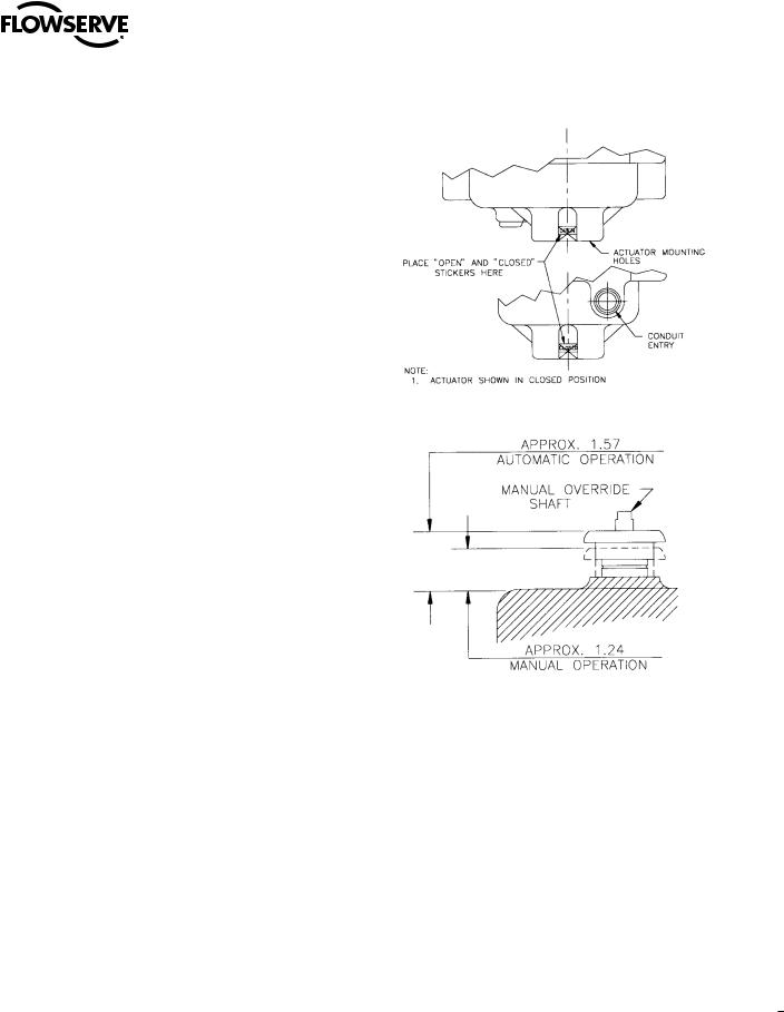
Manual Override
The principle of the design is such that when the manual override shaft is in the up position, the shaft is disconnected from the drive train. When the shaft is in the down position it does two things. One, the shaft trips a switch to disconnect the power to the motor and two, it releases the brake. By releasing the brake the motor can back drive along with the output. For 90 degree operation, the 250 in-lbs unit requires 1.6; the 700 in-lbs unit requires 3.1; the 1000 in-lbs unit requires 4.2; and 1500 in-lbs unit requires 6.3.
a Caution: Turn manual override shaft slowly. DO NOT jerk.
Manual Operation
1.The actuator cover should be securely attached.
2.Depress hub toward actuator cover.
3.Rotate the manual override shaft slowly; do not force.
4.The motor is now electrically disconnected.
5.Turn the manual override shaft clockwise for clockwise output.
6.Do not rotate actuator past full clockwise or counter-clockwise position.
Automatic Operation
1.Pull hub away from the actuator cover.
2.The motor is now electrically connected and ready for automatic operation.
3.The manual override shaft will freewheel.
Position Indication Stickers
Attached to the inside of the cover is a set of stickers with the words “CLOSED” and “OPEN”. These stickers are to be attached to the outside of the actuator near the base between the mounting feet. The stickers have an orange triangle on them, such that when properly attached
to the actuator, they will line up with the triangle on the output shaft. A sticker can be placed on either side of the unit to produce a visual indication of the opened and closed position of the actuator.
flowserve.com

Automax CENTURA™ CE Series FCD AXENIM0037-01 – 12/05
Common Parts Related to All Actuators
|
No. |
|
Item |
|
Material |
|
P/N |
|
Qty |
|
1 |
|
Painted Cover |
|
Cast Aluminum |
|
106100 |
|
1 |
|
|
|
|
|
|||||
|
|
|
|
|
|
|
|
|
|
|
2 |
|
5⁄16-24UNF HHCS/Shank |
|
Stainless Steel |
|
103233 |
|
8 |
|
3 |
|
5⁄16 Type A Washer |
|
Stainless Steel |
|
103715 |
|
8 |
|
4 |
|
1/2" Sleeve Bearing |
|
Sintered Bronze |
|
105590 |
|
1 |
|
|
|
|
|
|
|
|
|
|
|
5 |
|
Molded Oil Seal |
|
Nitrile |
|
105585 |
|
1 |
|
|
|
|
|
|
|
|
|
|
|
6 |
|
Manual Override Hub |
|
Black 141 Lexan |
|
105567 |
|
1 |
|
|
|
|
|
|
|
|
|
|
|
7 |
|
7/16 I.D. Klipring |
|
Stainless Steel |
|
106174 |
|
1 |
|
|
|
|
|
|
|
|
|
|
|
8 |
|
Handwheel (Optional) |
|
Black Plastic |
|
105974 |
|
1 |
|
|
|
|
|
|
|
|
|
|
|
9 |
|
Manual Override Shaft |
|
Steel/Plated |
|
105591 |
|
1 |
|
|
|
|
|
|
|
|
|
|
|
10 |
|
Brake Trip Washer |
|
Aluminum |
|
107065 |
|
1 |
|
|
|
|
|
|
|
|
|
|
|
11 |
|
Manual Override Coupler |
|
Steel/Plated |
|
106129 |
|
1 |
|
|
|
|
|
|
|
|
|
|
|
|
|
Manual Override Spring |
|
Spring Steel |
|
105593 |
|
1 |
|
|
|
|
|
|
|
|
|
|
|
|
|
1⁄16 Dia. Roll Pin |
|
Spring Steel |
|
103621 |
|
1 |
|
12 |
|
O-Ring, Base |
|
N674-70 Nitrile |
|
105584 |
|
1 |
|
|
|
|
|
|
|
|
|
|
|
13 |
|
CE1/CE2 Machined Base |
|
Cast Aluminum |
|
106098 |
|
1 |
|
|
|
|
|
|
|
|
|
|
|
|
|
CE4/CE7 Machined Base |
|
Cast Aluminum |
|
106099 |
|
1 |
|
|
|
|
|
|
|
|
|
|
|
|
|
CE5 Machined Base |
|
Cast Aluminum |
|
107503 |
|
1 |
|
|
|
|
|
|
|
|
|
|
|
14 |
|
3⁄8" Needle Bearing |
|
Steel/Plated |
|
105582 |
|
1 |
|
15 |
|
3⁄8" Sleeve Bearing |
|
Sintered Bronze |
|
105581 |
|
4 |
|
16 |
|
O-Ring, Output Shaft |
|
N674-70 Nitrile |
|
105583 |
|
1 |
|
|
|
|
|
|
|
|
|
|
|
17 |
|
11/2" Sleeve Bearing |
|
Sintered Bronze |
|
409944 |
|
1 |
|
|
|
|
|
|
|
|
|
|
|
18 |
|
CE1/CE2 Motor Plate |
|
Cast Aluminum |
|
106080 |
|
1 |
|
|
|
|
|
|
|
|
|
|
|
|
|
CE4/CE7 Motor Plate |
|
Cast Aluminum |
|
106081 |
|
1 |
|
|
|
|
|
|
|
|
|
|
|
|
|
CE5 Motor Plate |
|
Cast Aluminum |
|
107504 |
|
1 |
|
|
|
|
|
|
|
|
|
|
|
19 |
|
5⁄8" Sleeve Bearing |
|
Sintered Bronze |
|
105694 |
|
1 |
|
20 |
|
8-32 UNC Ground Screw |
|
Steel/Plated |
|
103627 |
|
1 |
|
|
|
|
|
|
|
|
|
|
|
21 |
|
#8 Cup Washer |
|
Brass |
|
105626 |
|
1 |
|
|
|
|
|
|
|
|
|
|
|
22 |
|
8-32 UNC x 5⁄8" Hex Screw |
|
Steel/Plated |
|
105577 |
|
5 |
|
23 |
|
8-32 UNC x 5⁄8" Phillips Hd. |
|
Steel/Plated |
|
105576 |
|
1 |
|
24 |
|
Actuator Bracket |
|
Steel/Plated |
|
108099 |
|
1 |
|
|
|
|
|
|
|
|
|
|
|
27 |
|
M.O. Cut-off Switch |
|
Plastic/Steel |
|
105769 |
|
1 |
|
|
|
|
|
|
|
|
|
|
|
28 |
|
Switch Insulator Gasket |
|
Vulcanized Fiber |
|
103675 |
|
5 |
|
|
|
|
|
|
|
|
|
|
|
29 |
|
4-40 UNC x 5⁄8" Phillips Hd.S |
|
Steel/Plated |
|
106146 |
|
2 |
|
30 |
|
4-40 UNC x 11/4" Phillips Hd. |
|
Steel/Plated |
|
100159 |
|
2 |
|
|
|
|
|
|
|
|
|
|
|
31 |
|
3⁄16" Higher Spacer |
|
Nylon |
|
105679 |
|
2 |
|
32 |
|
15 Amp Switch |
|
Plastic/Steel |
|
107765 |
|
2 |
|
|
|
|
|
|
|
|
|
|
|
33 |
|
3⁄16" Pop-in Bearing |
|
Plastic |
|
105851 |
|
1 |
|
34 |
|
Camshaft |
|
Steel/Plated |
|
107005 |
|
1 |
|
|
|
|
|
|
|
|
|
|
|
35 |
|
Large 4-Deg. Spline Shaft |
|
Plastic |
|
103571 |
|
1 |
|
|
|
|
|
|
|
|
|
|
|
|
|
1⁄16" Dia. Roll Pin |
|
Spring Steel |
|
103621 |
|
1 |
|
36 |
|
Small 4-Deg. Spline Shaft |
|
Plastic |
|
103572 |
|
1 |
|
|
|
|
|
|
|
|
|
|
|
|
|
1⁄16" Dia. Roll Pin |
|
Spring Steel |
|
103621 |
|
1 |
37 |
|
Switch Spring |
|
Spring Steel |
|
103714 |
|
1 |
|
|
|
|
|
|
|||||
|
|
|
|
|
|
|
|
|
|
|
38 |
|
Hi-Ramp Cam |
|
Plastic |
|
107322 |
|
2 |
|
|
|
|
|
|
|
|
|
|
|
Continued on Page |
|
|
|
|
|
|
||
 Loading...