


Installation
Instructions
Pac-Seal TM Type 21 and Type 31
Mechanical Shaft Seal
Experience In Motion
Description
Pac-Seal Types 21 and 31 feature uniquely designed crimped heads and hex-torque drive systems that provide a solid engineered advantage over other seal types. The Type 31 is the Pac-Seal designation for the Type 21 seal with hard face combination. Generally these are reserved for severe duty applications, in the Type 21 design envelope. Both Types
21 and 31 are available in double seal configurations and balanced versions.
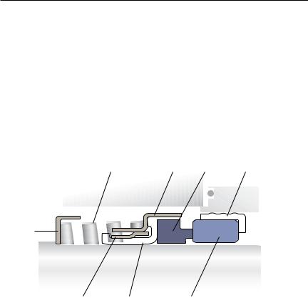
Type 21 and Type 31 Nomenclature |
|
Figure 1 |
|
16 |
28 |
15 |
126 |
142
2 157 14
Part Reference |
Description |
2 |
Seal Drive/Drive Band |
14 |
Stationary Face/Mating Ring |
15 |
Rotating Face/Primary Ring |
16 |
Spring |
28 |
Shell |
126 |
Gasket/Elastomer Cup/Cup Gasket |
142 |
Retainer/Spring Retainer |
157 |
Bellows Diaphragm/ Elastomer Bellows |
2
1 Equipment Check
1.1Follow plant safety regulations prior to equipment disassembly including, but not limited to, the following:
•Lock out motor and valves
•Wear designated personal safety equipment
•Relieve any pressure in the system
•Consult plant MSDS files for hazardous material regulations
1.2Disassemble pump in accordance with equipment manufacturer’s instructions and remove sealing arrangement.
1.3Check Seal documentation for seal design and materials of construction.
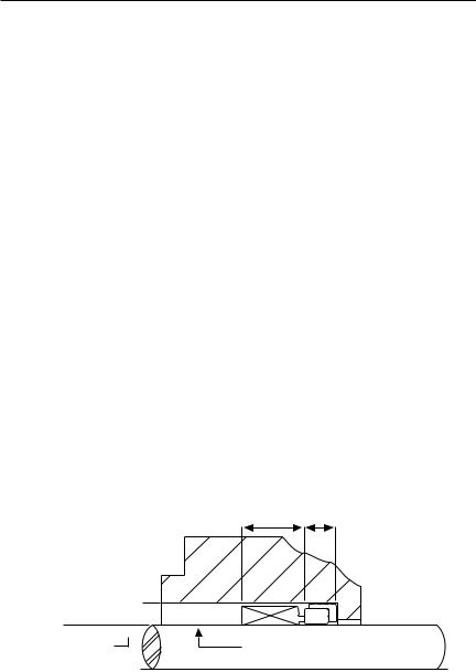
1.4Check shaft or pump sleeve outer diameter (OD), seal working height, mating ring width, and seal chamber bore to ensure they are dimensionally within the tolerances shown on the seal assembly drawing. See Figure 2.
Seal Chamber Requirements |
Figure 2 |
Seal Chamber Bore
-0.050 mm ( - 0.002 inch)
Shaft or sleeve OD  -0.050 mm ( - 0.002 inch)
Seal Working
Height Mating
Ring
Width
Sleeve or shaft finish to be 1.6 μm (63 μinch) Ra or better
•Bearings must be in good condition
•Maximum lateral or axial movement of shaft (end play) = 0.25 mm (0.010 inch) FIM
•Maximum shaft runout at face of seal housing = 0.05 mm (0.002 inch) FIM
•Maximum dynamic shaft deflection at seal housing = 0.05 mm (0.002 inch) FIM
•Verify proper shaft and bore lead in chamfers are present and within specifications. Difficulty and damage can be observed during seal installation without proper lead in chamfers.
3
 Loading...