


|
USER INSTRUCTIONS |
Limitorque Automax |
Installation |
CEA Series |
Operation |
FCD AXENIM2080-00-AQ – (01/15) |
Maintenance |
|
|
Experience In Motion

Limitorque Worcester Controls CEA Series FCD WCENIM2080-00-AQ 12/14
2

Limitorque Worcester Controls CEA Series FCD WCENIM2080-00-AQ 12/14
Contents
1. |
Important Notes |
5 |
||
|
|
|
|
|
2. |
Actuator Quick Start Guide for C-PRO and C-MOD Versions |
5 |
||
|
|
|
|
|
|
|
2.1 |
Wiring Diagrams |
7,8 |
|
|
|
|
|
|
|
2.2 Menu Tree |
9 |
|
|
|
|
||
|
3. |
Installation and Operation |
11 |
|
|
|
|
|
|
|
|
3.1 |
Flowserve Automax Valve Products |
11 |
|
|
|
|
|
|
|
3.2 |
Electrical Installation and Adjustment |
12 |
|
|
|
||
|
4. |
Calibration and Commissioning |
12 |
|
|
|
|
|
|
|
|
4.1 |
Travel Stop Adjustment |
12 |
|
|
|
|
|
|
|
4.2 |
Gear Train |
13 |
|
|
|
|
|
|
|
4.3 |
Rotation Speed Control |
13 |
|
|
|
|
|
|
|
4.4 |
Variable Torque Output |
13 |
|
|
|
|
|
|
|
4.5 |
Duty Cycle |
13 |
|
|
|
|
|
|
|
4.6 |
Heater and Thermostat |
13 |
|
|
|
|
|
|
|
4.7 |
HMI Display |
14 |
|
|
|
|
|
|
|
4.8 |
Programmable Parameters |
15 |
|
|
|
|
|
|
|
4.9 |
Alarm Output Setup |
20 |
|
|
|
|
|
|
|
4.10 Position Indicator |
21 |
|
|
|
|
||
|
5. |
Manual Override |
22 |
|
|
|
|
||
6. |
Performance and Technical Data |
23 |
||
|
|
|
||
7. |
Actuator Troubleshooting Guide (Electrical) |
24 |
||
|
|
|
||
8. |
Parts List |
25 |
||
|
|
|
|
|
3
flowserve.com

Limitorque Worcester Controls CEA Series FCD WCENIM2080-00-AQ 12/14
Using Flowserve Valves, Actuators
and Accessories
General Usage
The following instructions are designed to assist in unpacking, installing and performing maintenance as required on Flowserve products. Product users and maintenance personnel should thoroughly review this bulletin prior to installing, operating or performing any maintenance.
In most cases Flowserve valves, actuators and accessories are designed for specific applications with regard to pressure, temperature and media. For this reason they should not be used in other applications without first contacting the manufacturer.
Terms Concerning Safety
The safety terms WARNING, CAUTION and NOTE are used in these instructions to provide additional information on important aspects of the CEA.
a WARNING: indicates that death, severe personal injury and/or substantial property damage can occur if proper precautions are not taken.
a CAUTION: indicates that minor personal injury and/or property damage can occur if proper precautions are not taken.
NOTE: provides additional technical information, which may not be obvious even to qualified personnel.
Compliance with all other notes regarding transport, assembly, operation, maintenance and technical documentation is essential in order to avoid conditions or occurrences that might directly or indirectly cause severe personal injury or property damage.
Protective Clothing
Flowserve products are often used in dangerous applications (e.g. extremely high pressures, or with flammable, combustible, toxic or corrosive media). In particular, valves with bellows seals point to such applications. When performing service, inspection or repair operations, always ensure that the valve is depressurized, the actuator is powered off and that the valve has been cleaned and is free from harmful substances. In such cases pay particular attention to personal protection (protective clothing, gloves, glasses, etc.).
4
Qualified Personnel
Qualified personnel are people who, on account of their training, experience and instruction, and their knowledge of relevant standards, specifications, accident prevention regulations and operating conditions, have been authorized by those responsible for the safety of the plant and its employees to perform the necessary work and who can recognize and avoid possible dangers.
Installation
a WARNING: Before installation, check the order number, serial number and/or the tag number to ensure the actuator is correct for the intended application.
Do not insulate extensions that are provided for hot or cold services.
Fire protection must be provided by the user.
Spare Parts
Use only original Flowserve spare parts. Flowserve cannot accept responsibility for any damages that occur from using spare parts or fastening materials from other manufacturers. If Flowserve products, like sealing materials, have been in storage for longer periods, check these for corrosion or deterioration before using. Fire protection for Flowserve products must be provided by the user.
Service/Repair
To avoid injury to personnel and damage to products, users must strictly adhere to safety terms. Modifying this product, substituting non-OEM parts, or using maintenance procedures other than outlined in this instruction could affect performance and be hazardous to personnel and equipment, and may void existing warranties. Between the actuator and valve, there are moving parts. To avoid injury, Flowserve provides pinch-point-protection in the form of cover plates, especially where side-mounted positioners are fitted. If these plates are removed for inspection, service or repair, the cover plates must be refitted after the work is complete.
In addition to the operating instructions and the obligatory accident prevention directives valid in the country of use, all recognized regulations for safety and good engineering practices must be followed.
a WARNING: Before products are returned to Flowserve for repair or service, Flowserve must be provided with a certificate which confirms that the product has been decontaminated and is clean. Flowserve will not accept deliveries if a certificate has not been provided (a form can be obtained from Flowserve).

Limitorque Worcester Controls CEA Series FCD WCENIM2080-00-AQ 12/14
Storage
In many cases, Flowserve products are manufactured from stainless steel. Products not manufactured from stainless steel are provided with an epoxy resin coating. This means that Flowserve products are well protected from corrosion. Nevertheless, Flowserve products must be stored in a clean, dry environment.
ingress and harsh environments that may result in deterioration of internal components and void the unit’s warranty.
During final field installation, ensure that all cable entries are correctly sealed in accordance with National Standards or Regulatory Authorities. All temporary transit plugs must be removed and any unused cable entries closed in an approved manner.
Valve and Actuator Variations
These instructions cannot claim to cover all details of all possible product variations, nor can they provide information for every possible example of installation, operation or maintenance. This means that the instructions normally include only the directions to be followed by qualified personnel where the product is being used, for its defined purpose. If there are any uncertainties, particularly in the event of missing product-related information, clarification must be obtained via the appropriate Flowserve sales office.
Unpacking
Each delivery includes a packing slip. When unpacking, check the delivered actuator and accessories using this packing slip.
Report transport damage to the carrier immediately.
In case of discrepancies, contact your nearest Flowserve sales office.
1. Important Notes
•Please read this manual entirely before attempting to install or operate your CEA actuator. A full understanding of the installation and operation options will assist you in installing the actuator in the most effective manner. The CEA actuator is designed for long life even in harsh environments.
•All actuator enclosures are sealed by O-rings and cable entries are supplied with threaded plugs to protect the terminal compartment until the unit is wired. If the actuator cannot be installed immediately, it is recommended that it be stored in a clean, dry place, preferably in an area that is not subject to large fluctuations in temperature.
•Disconnect all incoming power before opening any cover on the actuator. The user/operator must ensure that safe working practices are employed at all times and are in accordance with local or national standards that are enforced at the particular site.
•To install and operate the actuator, only the terminal compartment cover needs to be removed. The actuator is factory calibrated according to nameplate information and is ready to install and operate upon receipt.
NOTE: If the controls cover is removed, electrical components are exposed to the atmosphere. Avoid exposure to moisture
2.Actuator Quick Start Guide
for C-PRO and C-MOD Versions
CEA model sizes 15/60/150 use ISO mounting F05/F07 with STAR drive interface as standard. The baseplate incorporates both mounting patterns with F07 required for size 150 torque output. A third mounting pattern with larger diameter is also provided for custom mounting installations.
1.Prior to assembly, check the mounting surfaces, the stem adaptor and the bracket to assure proper fit.
2.Manually open and close the valve to ensure smooth operation.
3.Be sure the valve and actuator rotate in the same direction and are in the same position (i.e. valve open, actuator open).
4.Secure the valve with the stem vertical.
5.Bolt the bracket to the valve and place the stem adaptor on the valve stem.
6.Position the actuator over the valve and lower to engage the stem adaptor to the actuator output drive. Continue to lower until the actuator rests on the bracket mounting surface. In order to align the bolt holes, it may be necessary to turn or rotate the actuator a few degrees.
7.Bolt the actuator to the bracket.
8.Stroke the actuator several times to assure proper operation with no binding of the stem adaptor.
a CAUTION: Fastener length must be less than mounting hole depth for proper mounting and to avoid damage to mounting base.
a CAUTION: Misalignment may reduce actuator cycle life and
cause premature failure. |
|
Travel stops are provided with 90o rotation angle models. They are fac- |
|
tory set at 0o and 90o position. If travel stops are adjusted inward, it is |
|
necessary to perform an AutoCalibration to recalibrate rotation limits. |
5 |
If travel stops are adjusted outward, it is recommended to perform an |
|
AutoCalibration to recalibrate rotation limits. |
|
flowserve.com

Limitorque Worcester Controls CEA Series FCD WCENIM2080-00-AQ 12/14
Normally there are no orientation restrictions for actuator mounting; consult factory with any questions. Typical installations include InLine mounting with the handwheel in line with the piping and CrossLine mounting with the handwheel cross line with the piping.
NOTE: Mechanical assistance may be required to remove and tighten the threaded covers. A flat edge screwdriver 10 inches or longer may be of assistance.
NOTE: It is not necessary to remove the indicator dome on the Controls Cover for removal.
Flat Edge Screwdriver (recommended)
Round Edge Screwdriver (not recommended)
X
After commissioning the actuator, the threaded cover(s) will need to be installed in reverse fashion. Rotate by hand until difficult to turn (about 90% complete). Use mechanical assistance until you feel the cover “bottom out.” For the controls cover to be properly sealed, the gap between the cover and the housing should be no more than 0.010 inch.
With the actuator in full CW position, the entire RED closed indicator should be shown in the viewing window of the dome. This is the factory default setting. User may change to CCW/Open position.
a WARNING: All threaded covers must be installed with the above criteria, otherwise NEMA/IP and Hazardous Area ratings could be compromised.
6
Operation
C-PRO version
The C-PRO, ON/OFF voltage control actuator ships from the factory calibrated and ready to operate. It is not necessary to remove the Controls Cover if factory settings are suitable. Wire the actuator according to the wiring diagram located inside the Terminal Block cover.
Key default settings include:
•Factory calibrated for 0-90 degree operation
•CCW to Open, CW to Close
•Fastest operating speed (listed on nameplate)
•Maximum rated torque (listed on nameplate)
•L1 and L2 are for input voltage 120 or 240VAC (Consult Factory for other AC/DC voltages)
•Terminals 20, 21, 22 and 23
-Terminal 20 = voltage command common
-Terminal 21 = voltage command OPEN
-Terminal 22 = voltage command CLOSED
-Terminal 23 = voltage command MID
•Terminals 1 and 2 are Normally Open (NO) dry relay contacts for OUTPUT 1 (CCW)
•Terminals 3 and 4 are Normally Open (NO) dry relay contacts for OUTPUT 2 (CW)
•Terminals 5 and 6 are Normally Open (NO) dry relay contacts for OUTPUT 3 (Torque or MID)
•Terminals 7 and 8 are Normally Open (NO) dry relay contacts for OUTPUT 4 (Compartment Temp)
NOTE: L1 and L2 are to be powered at all times. Remote voltage commands can be any voltage between 24VDC-240VDC or 24VAC to 240VAC: 4/5 wire power and control scheme.
For 3 wire power and control scheme, consult Flowserve.
Limitorque Worcester Controls CEA Series FCD WCENIM2080-00-AQ 12/14
C-MOD version
The C-MOD or Modulating control actuator ships from the factory calibrated and ready to operate. It is not necessary to remove the Controls Cover if factory settings are suitable. Wire the actuator according to the wiring diagram located inside the Terminal Block cover.
Key default settings include:
•Factory calibrated for 0-90 degree operation
•Direct Acting CCW to Open
•L1 and L2 are for input voltage 120 or 240VAC (Consult Factory for other AC/DC voltages)
•Terminals 11, 12, 13 and 14
-Terminal 11 = + 4-20mA current source (input)
-Terminal 12 = ( - ) 4-20mA current source (input)
-Terminal 13 = + Loop Powered 24VDC + 4-20mA current (output)
-Terminal 14 = ( - ) Loop Powered 24VDC + 4-20mA current (output)
•Terminals 1 and 2 are Normally Open (NO) dry relay contacts for OUTPUT 1 (CCW)
•Terminals 3 and 4 are Normally Open (NO) dry relay contacts for OUTPUT 2 (CW)
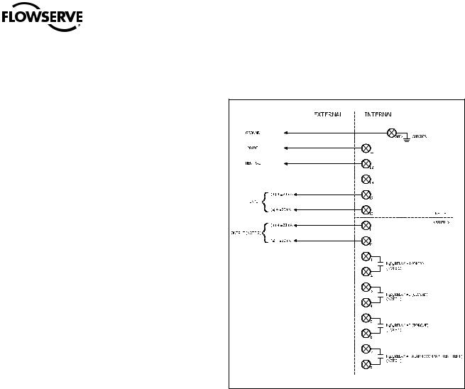
2.1 C-MOD Wiring |
•Terminals 5 and 6 are Normally Open (NO) dry relay contacts for OUTPUT 3 (Torque or MID)
•Terminals 7 and 8 are Normally Open (NO) dry relay contacts for OUTPUT 4 (Compartment Temp)
NOTE: L1 and L2 are to be powered at all times
NOTE: 4-20mA output is to be loop powered with 24VDC. Voltage range 13-24VDC.
NOTE 1: Contact rating = 16amp @ 250VAC, dry contact. All outputs are programmable, remote voltage inputs are 12VDC
to 240VAC for Open, Closed, Mid/Dribble terminals (20,21,22,23)
7
flowserve.com

Limitorque Worcester Controls CEA Series FCD WCENIM2080-00-AQ 12/14
C-PRO Wiring
ON/OFF with Isolated Voltage Command Control
C-PRO Wiring
ON/OFF with Non-Isolated Voltage Command Control
NOTE 1: Contact rating = 16amp @ 250VAC, dry contact. All outputs are programmable, remote voltage inputs are 12VDC to 240VAC for Open, Closed, Mid/Dribble terminals (20,21,22,23).
NOTE 2: 208 - 240VAC, 3 phase (future)
Standard Baseplate Mounting
|
.974 |
.974 |
|
|
|
|
|
|
|
|
M8x1.25 - TAP |
.702 |
.702 |
DOUBLE SQUARE TORQUE NUT |
|
|
BORE TORQUE NUT |
|
|
||
0.51 DEEP |
|
|
|
|
|
|
|
|
||
|
|
DESCRIPTION |
"A" (SQUARE) |
DEPTH |
DESCRIPTION |
"BORE" |
"T" |
"W" |
DEPTH |
|
|
|
|
||||||||
(F07) M8X1 / (FA07) 5/16-18 UNC - TAP |
|
|
0.669 |
0.669 |
0.787 |
0.875-1/4x1/4 |
0.879 |
0.991 |
0.250 |
1.63 |
0.67 DEEP |
|
|
0.551 |
0.551 |
0.630 |
0.875-1/4x3/16 |
0.879 |
0.960 |
0.250 |
1.63 |
(F05) M6X1 / (FA05) 1/4-20 UNC - TAP |
|
|
|
|
|
|
|
|
|
|
0.51 DEEP |
|
|
|
|
|
|
|
|
|
+.002 |
|
|
|
|
|
|
|
|
|
|
|
|
|
|
|
45° |
|
|
|
|
"W" - .000 |
|
|
|
1.890 |
|
|
"T"+.008 |
|
45° |
|
||
|
|
+.004 |
|
|
|
|
||||
|
|
TYP. |
|
|
|
|
|
|||
|
|
|
"A" - .000 |
|
|
|
- .000 |
|
|
|
|
|
.702 .974 |
|
|
|
|
|
|
|
|
|
|
|
+.004 |
|
|
|
|
|
|
|
|
|
|
"A" - .000 |
|
|
|
|
|
|
|
|
|
.702 |
|
|
R.08 MAX. |
|
|
|
|
|
|
|
.974 |
|
|
|
|
|
|
||
|
|
|
|
|
TYP. |
|
|
|
|
|
8 |
|
1.890 |
|
|
|
|
+.004 |
|
|
|
|
TYP. |
|
|
|
"BORE" - .000 |
|
|
|
||
|
|
|
|
|
|
|
|
|
||
DOUBLE SQUARE TORQUE NUT |
BORE TORQUE NUT |
|
|
MOUNTING |
|
BLANK TORQUE NUT |
|
(F05/FA05 & F07/FA07) |
|

Limitorque Worcester Controls CEA Series FCD WCENIM2080-00-AQ 12/14
2.2 Menu Tree
C-PRO & C-MOD Menu Tree - SW120
Basic Menu* |
|
|
|
|
|
|
|
Standard* |
1 (Pos*/Alarm) |
Show alarm |
|||
|
|
|
|
|
|
|
|
Turns |
2 (Pos*/Alarm) |
Deviation |
|
|
|
|
|
|
|
|
|
|
|
Manual |
3 (Pos/Alarm*) |
Limit 1 |
|
|
|
Calibrate |
|
Rotation |
|
|
|
|
|
Mid Pos |
4 (Pos/Alarm*) |
Limit 2 |
|
|
|
|
|
Outputs |
|
|
|
|
|
|
ALARMS |
|
Torque |
|
|
|
|
AutoCal |
|
|
|
|
|
|
|
|
Compa temp |
||
|
|
Expert Cal |
|
Set Point |
|
Model |
|
|
|
|
Motor temp |
||
|
|
|
|
Transm |
|
Open |
|
|
|
|
|
|
|
Set Up Pro |
|
Torque |
|
|
|
Closed |
|
|
|
|
|
|
|
|
|
Speed |
|
|
|
|
|
|
|
|
|
|
|
|
|
Direction |
|
|
|
Open Speed |
|
|
|
|
|
|
|
|
|
Curr Limit |
|
CCW/CW |
|
Close Speed |
|
|
|
|
|
|
|
Status |
|
0 0 Service |
|
|
|
|
|
|
N cycles |
|
Lo MotrVlt |
|
|
|
|
|
|
|
|
|
|
|
|
||||
|
|
IN Service* |
|
|
|
Pos |
|
|
Acc travel |
|
MotrTmpOOR |
||
|
|
|
|
|
|
Set & Pos* |
|
|
Mean dev |
|
MotrOvrTrq |
||
Protection |
|
NO* |
|
|
|
Set & Dev |
|
|
# of reset |
|
IGBT Open |
|
|
|
|
YES |
|
Enter Code |
|
Torque |
|
|
Run time |
|
HallldxCrt |
|
|
|
|
|
|
|
|
motor temp |
|
|
Extreme Temp |
PMCB Reset |
|||
Shift |
|
Basic Menu* |
|
|
|
comp temp |
|
|
Histogram |
|
HallldxLmp |
||
Read |
|
Full Menu |
|
|
|
show LCS |
|
|
Pos graph |
|
BakEMFFaul |
||
|
|
|
|
|
Statistics |
|
|
Reset stats |
IRAM Fault |
||||
Man/Auto |
|
|
|
|
|
|
|
|
Diagnostic |
|
HWOverTorq |
||
|
AUT, OK=MAN |
|
MAN,OK=AUTO |
|
|
|
|
COP Fault |
|
|
|||
Full Menu |
|
|
|
|
|
|
|
|
|
|
IGBT Short |
|
|
|
|
|
|
|
|
|
|
|
|
|
|
|
|
Shift |
|
Basic Menu |
|
|
|
|
|
|
|
|
|
|
|
|
|
|
|
|
|
|
|
C-MOD Dedicated |
|
|
|||
|
|
Full Menu |
|
|
|
|
|
|
Character |
|
|
|
|
|
|
|
|
|
|
|
|
|
Custom char |
|
|
|
|
Setup Full |
|
|
|
|
|
|
|
|
Current range (split range) |
|
|
||
|
|
Character |
|
linear* |
|
|
|
|
Trvl ctrl |
|
|
|
|
|
|
|
equal % |
|
|
|
|
Loss of setpoint signal position |
|
|
|||
|
|
|
|
quick open |
|
|
|
|
Loss of setpoint signal time |
|
|
||
|
|
|
|
custom |
|
|
|
|
Setpoint selector |
|
|
|
|
|
|
|
|
sqr root |
|
|
|
|
Loss of position feedback action |
|
|
||
|
|
Custom char |
|
|
# of points |
|
|
Slow shaft detection percentage |
|
|
|||
|
|
|
|
custom curve |
|
|
Unit address |
|
|
|
|||
|
|
|
|
|
0% = 4.0mA* |
|
|
|
|
|
|
|
|
|
|
|
|
|
|
|
|
|
|
|
|
||
|
|
Current range |
|
|
100% = 20.0mA* |
|
free* |
|
|
|
|
|
|
|
|
|
|
|
|
|
|
cutoff |
free* |
Cutoff Low |
|
LO = 1.0% |
|
|
|
|
|
Set low |
|
|
|
limited |
cutoff |
Cutoff High |
HI = 99.0% |
||
|
|
Trvl ctrl |
|
Set high |
|
|
|
|
limited |
Limit Low |
|
LO = 0.0% |
|
|
|
|
|
Values |
|
|
|
|
|
Limit High |
|
HI = 100.0% |
|
|
|
|
|
|
Direct |
|
|
|
|
|
|
|
|
|
|
|
|
|
|
|
|
|
|
|
|
||
|
|
Transmitter |
|
Direction |
Reverse |
Position |
|
|
|
|
|
|
|
|
|
|
|
Pos/Set |
|
Setpoint |
|
|
|
|
|
|
|
|
|
|
|
|
|
|
|
Setpoint |
|
%*, mA, degrees |
|
|
|
|
|
|
|
|
|
|
|
Position |
|
%*, degrees |
Position |
||
|
|
|
|
Language |
|
|
|
Torque |
|
Nm, Lb-in*, Lb-Ft |
Set & Pos* |
||
|
|
Appearance |
|
Units |
|
|
|
Temp |
|
C, F*, K |
|
Set & Dev |
|
|
|
|
|
Default Display |
|
|
|
|
|
Menu |
|||
|
|
|
|
Start Logo |
On*/OFF |
|
|
|
|
|
|
|
|
|
|
|
|
Orientation |
Normal*,Flipped |
|
|
|
|
|
|
|
|
|
|
|
|
HW rev |
|
|
|
Message |
|
|
|
|
|
|
|
|
|
|
|
|
|
|
|
|
|
||
|
|
|
|
SW rev |
|
|
|
Tag |
|
|
|
|
|
|
|
Devicedata |
|
Capability |
|
|
|
Descriptor |
|
|
|
|
|
|
|
|
|
HART/MBUS |
|
|
|
Date |
|
|
|
|
|
|
|
|
|
|
|
|
|
Device ID |
|
ID = XXXXXX (= serial no) |
|||
|
|
|
|
|
|
|
|
Modbus adr |
|
ADDR = XXX |
|
|
|
|
|
|
|
|
|
|
|
Assembly No. |
|
|
|
|
|
Tuning |
|
Close Time |
|
MIN = 0.0s |
|
|
|
Universal Cmd Rev |
|
|
|
|
|
|
|
Open Time |
|
MIN = 0.0s |
|
|
|
Special Cmd Rev |
|
|
|
|
|
|
|
Deadband |
|
D = 1.0% |
|
|
|
Burst |
|
|
|
|
|
|
|
Expert |
|
|
|
|
|
|
|
|
|
|
|
|
|
|
|
Control |
PID Parameters |
|
|
|
|
|
|
|
|
|
|
|
|
|
Stroketime |
|
CCW = X.Xs |
|
|
|
|
|
|
FACT SET |
|
(press OK for 3 seconds to set default settings) |
|
CW = Y.Ys |
|
|
|
|
|
||||
|
|
|
|
|
|
|
|
||||||
Read |
|
|
|
|
|
|
|
|
|
|
|
9 |
|
|
|
|
|
|
|
|
|
|
|
|
|||
|
|
|
|
|
|
|
|
|
|
|
|
|
|
MAN/AUTO |
|
|
|
|
|
|
|
|
|
|
|
|
|
Calibrate |
|
Duplicated - see Basic Menu tree |
|
|
|
|
|
|
|
||||
Setup Pro |
|
|
|
|
|
|
|
|
|
|
|
|
|
Status |
|
|
|
|
|
|
|
|
|
|
|
|
|
Protection |
|
|
|
|
|
|
|
|
|
|
|
|
|
Note: (*) indicates factory default setting
flowserve.com
 Loading...