


Installation
Instructions
Durametallic® SL-5000 and SL-5200 Seals
Cartridge Slurry Seals
Experience In Motion
SL-5000 and SL-5200 Cartridge Seals are complete preset seal assemblies which include the sleeve and gland. No seal settings or measurements are required. They are especially suitable for pumps and rotating equipment handling abrasive slurries. The SL-5000 is a single seal design and the SL-5200 is a dual seal.
1 Equipment Check
1.1Follow plant safety regulations prior to equipment disassembly:
•lock out motor and valves.
•wear designated personal safety equipment.
•relieve any pressure in the system.
•consult plant MSDS files for hazardous material regulations.
1.2Disassemble equipment to allow access to seal installation area.
1.3Remove all burrs, nicks, or scratches, and sharp edges from the shaft / sleeve including sharp edges of keyways and threads. Replace worn shaft or sleeve. Make sure the seal housing bore, face, and sealing fluid flush taps are clean and free of burrs and sharp edges that might damage gaskets.
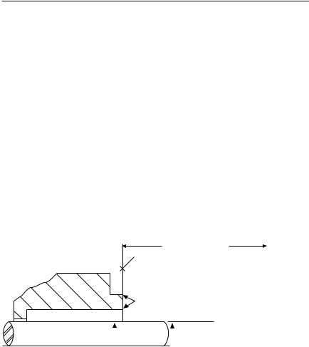
1.4Check requirements for shaft, sleeve and seal chamber, See Figure 1.
Seal Chamber Requirements |
Figure 1 |
Seal housing bore to have 3.2 μm (125 μinch) Ra finish or better
To first obstruction
Face of seal housing to be square to the axis of the shaft to within 0.0005 mm/mm (0.0005 inch/inch) of seal chamber bore TIR
and have a 1.6 μm (63 μinch) Ra finish or better
Gland pilot can be at either of these register locations, concentric to within 0.125 mm (0.005 inch) of shaft or sleeve OD TIR
Sleeve or shaft finish to be |
|
|
|
Shaft or sleeve OD |
|
|
|
|
+0.000 mm (+0.000 inch) |
ANSI |
|
|
|
|
|||
0.8 μm (32 μinch) Ra or better |
|
|
-0.050 mm (-0.002 inch) |
||
|
|
|
|
|
|
|
|
|
|
+0.000 mm (+0.000 inch) |
API 610/682 |
• Bearings must be in good condition |
|
|
-0.025 mm (-0.001 inch) |
DIN/ISO |
|
• Maximum lateral or axial movement of shaft (end play) = 0.25 mm (0.010 inch) TIR
• Maximum shaft runout at face of seal housing = 0.05 mm (0.002 inch) TIR
• Maximum dynamic shaft deflection at seal housing = 0.05 mm (0.002 inch) TIR
|
The images of parts shown in these instructions may differ visually from the actual |
2 |
parts due to manufacturing processes that do not affect the part function or quality. |
|

1.5Check assembly drawing included with the seal for specific seal design, materials of construction, dimensions, and piping connections.
1.6Check shaft or sleeve OD seal chamber bore, seal chamber depth, and distance to the first obstruction to ensure that they are dimensionally the same as shown on the seal assembly drawing.
1.7Check gland pilot and bolt holes to ensure they are adaptable to the equipment and are the same as shown on the assembly drawing.
1.8Handle all seal parts with care, they are manufactured to precise tolerances. The seal faces on the rotating and stationary faces are of special importance. These two sealing faces are lapped flat to within three light bands (34.8 millionths of an inch). Keep the seal faces perfectly clean at all times.
2 Installation
2.1Lubricate the shaft lightly with silicone lubricant before installing the seal assembly on the shaft.
2.2Install the complete cartridge seal assembly over the shaft and ease it into position. Care should be exercised when passing the sleeve incorporating the O-ring over any keyways or threads that may be present. Any steps or shoulders on the shaft should be beveled to prevent damage (pinching and cutting) of the O-ring sleeve gasket during installation. Attach the gland bolts loosely, hand tight, to the face of the seal chamber.
2.3After the pump assembly has been completed with the impeller, shaft, coupling, and bearing in their respective running or operating position, tighten the gland bolts to the seal chamber, evenly cross staggering the adjustment of the bolts.
2.4Be sure the set screw material is harder than the shaft material to bite into the shaft and hold the required load. Tighten the sleeve collar set screws to the shaft by cross staggering the adjustment.
2.5Remove the setting devices from between the sleeve drive collar and gland, and store for future use.
2.6The seal is set and ready for operation.
3
 Loading...