


Installation
Instructions
Durametallic® LS-300 Series
Multiple lip seal cartridge for high viscosity pumps
Experience In Motion
1 Equipment Check
1.1Follow plant safety regulations prior to equipment disassembly:
•lock out motor and valves.
•wear designated personal safety equipment.
•relieve any pressure in system.
•consult plant MSDS files for hazardous material regulations.
1.2Disassemble equipment to allow access to seal installation area.
1.3Remove all burrs and sharp edges from the shaft or sleeve including sharp edges of keyways and threads. Replace worn shaft or sleeve. Make sure the seal housing bore and face are clean and free of burrs.
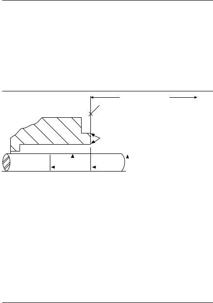
1.4Check requirements for shaft, sleeve and seal housing, see Figure 1.
Seal Chamber Requirements Figure 1
To first obstruction
Face of seal housing to be square to the axis of the shaft to within 0.013 mm per millimeter (0.0005 inches) of seal chamber bore FIM and have a √1.6 μm (63 μinch) Ra finish or better
|
|
|
|
|
|
|
|
|
|
Gland pilot can be at either of these |
||||
|
|
|
|
|
|
|
|
|
|
register locations, concentric to within |
||||
|
Seal housing bore to have √3.2 μm |
|
|
|
0.13 mm (0.005 inch) FIM of shaft or sleeve OD |
|||||||||
|
|
|
|
|
|
|
|
|
||||||
|
(125 μinch) Ra finish or better |
|
Scribe |
|
|
|
|
|||||||
|
Scribe |
|
|
|
|
|
Shaft or sleeve OD |
|||||||
|
|
|
|
|
||||||||||
|
Mark |
B |
|
|
|
Mark |
A |
|
|
+0.000 mm (+0.000 inch) |
||||
|
|
|
|
|||||||||||
|
|
|
|
|
|
|
|
|
|
|
|
|
-0.050 mm (-0.002 inch) ANSI |
|
Sleeve or shaft finish to be |
|
|
|
|
|
|
|
|||||||
|
|
|
|
|
|
|
|
|
+0.000 mm (+0.000 inch) API 610/682 |
|||||
|
|
|
|
|
|
|
|
|
||||||
•Bearings must be in good condition -0.025 mm (-0.001 inch) DIN/ISO
•Maximum lateral or axial movement of shaft (end play) = 0.25 mm (0.010 inch) FIM
•Maximum shaft runout at face of seal housing = 0.05 mm (0.002 inch) FIM
•Maximum dynamic shaft deflection at seal housing = 0.05 mm (0.002 inch) FIM
1.5Check assembly drawing included with the seal for specific seal design, materials of construction, dimensions, and piping connections.
1.6Check shaft or sleeve OD, box bore, box depth, and distance to the first obstruction to ensure that they are dimensionally the same as shown on the seal assembly drawing.
1.7Check gland pilot and bolt holes to ensure they are adaptable to the equipment and are the same as shown on the assembly drawing. Many cartridge Flowserve seal designs include centering tabs, eccentric washers, or centering plates that do not require a gland pilot.
1.8Handle all seal parts with care, they are manufactured to precise tolerances.0.8 μm (32 μinch) Ra or better
2 Cartridge Flowserve Seal Installation
2.1Lubricate the shaft or sleeve lightly with silicone lubricant provided with the seal before installing any seal parts.
2.2Install the complete cartridge Flowserve seal assembly on the shaft and position it close to the bearing housing with the seal orientated toward the pump.
The images of parts shown in these instructions may differ visually from the actual parts due to manufacturing processes that do not affect the part function or quality.
2
 Loading...