


|
USER INSTRUCTIONS |
MX/DDC-100 Field Unit |
Installation |
FCD LMENIM2329-01 – 03/11 |
Operation |
|
Maintenance |
|
|
Experience In Motion

MX/DDC-100 Field Unit Installation and Maintenance FCD LMENIM2329-01 – 03/11
MX/DDC-100 Field Unit Installation and Operation Manual
©2011 Copyright Limitorque. All rights reserved. Printed in the United States of America.
Disclaimer
This document is meant for use with MX Installation and Operation Manual for MX-05 through MX-40. Information in this document is also applicable to MX-85 through MX-150. No part of this book shall be reproduced, stored in a retrieval system, or transmitted by any means, electronic, mechanical, photocopying, recording, or otherwise without the written permission of Limitorque. While every precaution has been taken in the preparation of this book, the publisher assumes no responsibility for errors or omissions. Neither is any liability assumed for damages resulting from the use of the information contained herein.
This document is the proprietary information of Limitorque, furnished for customer use ONLY. No other uses are authorized without written permission from Limitorque.
Limitorque reserves the right to make changes, without notice, to this document and the product it describes. Limitorque shall not be liable for technical or editorial errors or omissions made herein; nor for incidental and consequential damages resulting from the furnishing, performance or use of this document.
The choice of system components is the responsibility of the buyer, and how they are used cannot be the liability of Limitorque. However, Limitorque’s sales team and application engineers are always available to assist you in making your decision.
This manual contains information that is correct to the best of Limitorque’s knowledge. It is intended to be a guide and should not be considered as a sole source of technical instruction, replacing good technical judgment, since all possible situations cannot be anticipated. If there is any doubt as to exact installation, configuration, and/or use, call Limitorque at (434) 528-4400. The latest revisions to this document are available at www.flowserve.com.
2

|
|
|
MX/DDC-100 Field Unit Installation and Maintenance |
FCD LMENIM2329-01 – 03/11 |
|
|
Contents |
|
|
|
|||
1 |
Introduction |
|
5 |
|
|
|
|
|
|
|
|
|
|
|
1.1 |
Purpose |
5 |
|
|
|
|
|
|
|
|
|
|
|
1.2 |
How to Use this Manual |
5 |
|
|
|
|
|
|
|
|
|
|
|
1.3 |
User Safety |
5 |
|
|
|
|
|
|
|
|
|
|
|
1.4 |
User Knowledge |
6 |
|
|
|
|
|
|
|
|
|
|
|
1.5 |
DDC-100 System Capabilities and Features |
6 |
|
|
|
|
|
|
|
|
|
|
|
1.6 |
General Specifications |
7 |
|
|
|
|
|
|
|
|
||
2 |
System Components |
8 |
|
|
||
|
|
|
|
|
|
|
|
2.1 |
Introduction |
8 |
|
|
|
|
|
|
|
|
|
|
|
2.2 |
Hardware |
8 |
|
|
|
|
|
|
|
|
|
|
|
|
2.2.1 |
MX Actuator |
9 |
|
|
|
|
|
|
|
|
|
|
|
2.2.2 |
DDC–100 Field Unit |
9 |
|
|
|
|
|
|
|
|
|
|
|
2.2.3 |
Host Controller |
10 |
|
|
|
|
|
|
|
|
|
|
|
2.2.4 |
Master Station II |
11 |
|
|
|
|
|
|
|
|
|
|
|
2.2.5 |
Network Cable |
12 |
|
|
|
|
|
|
|
|
|
|
2.3 |
Software |
13 |
|
|
|
|
|
|
|
|
|
|
|
|
2.3.1 |
Modbus Protocol |
13 |
|
|
|
|
|
|
|
|
|
|
|
2.3.2 |
Modbus Function Codes |
14 |
|
|
|
|
|
|
|
|
|
|
|
2.3.3 |
Modbus Function Code 01 (Read Coil Status) |
14 |
|
|
|
|
|
|
|
|
|
|
|
2.3.4 |
Modbus Function Code 02 (Read Input Status) |
15 |
|
|
|
|
|
|
|
|
|
|
|
2.3.5 |
Modbus Function Code 03 (Read Holding Register) |
17 |
|
|
|
|
|
|
|
|
|
|
|
2.3.6 |
Modbus Function Code 04 (Read Input Register) |
21 |
|
|
|
|
|
|
|
|
|
|
|
2.3.8 |
Modbus Function Code 06 (Preset Single Register) |
23 |
|
|
|
|
|
|
|
|
|
|
|
2.3.9 |
Modbus Function Code 08 (Diagnostics) |
26 |
|
|
|
|
|
|
|
|
|
|
|
2.3.10 |
Modbus Function Code 15 (Force Multiple Coils) |
27 |
|
|
|
|
|
|
|
|
|
|
|
2.3.11 |
Modbus Function Code 16 (Preset Multiple Registers) |
28 |
|
|
|
|
|
|
|
||
3 |
Installation and Configuration |
30 |
|
|
||
|
|
|
|
|
|
|
|
3.1 |
Site and Network Cable Preparation |
30 |
|
|
|
|
|
|
|
|
|
|
|
|
3.1.1 |
Site Preparation |
30 |
|
|
|
|
|
|
|
|
|
|
|
3.1.2 |
Network Cable Preparation |
30 |
|
|
|
|
|
|
|
|
|
|
3.2 |
Installation Verification |
38 |
|
|
|
|
|
|
|
|
|
|
|
|
3.2.1 |
Network Cabling Installation Verification |
38 |
|
|
|
|
|
|
|
|
|
|
|
3.2.2 |
Field Unit Installation Verification |
38 |
|
|
|
|
|
|
|
|
|
|
3.3 |
Field Unit Configuration |
39 |
|
|
|
|
|
|
|
|
|
|
|
|
3.3.1 |
Configuring Field Unit Parameters |
39 |
|
|
|
|
|
|
|
|
|
|
3.4 |
Configuration Confirmation |
44 |
|
|
|
|
|
|
|
|
|
|
|
|
3.4.1 |
Checking Connections |
44 |
|
|
|
|
|
|
|
|
|
|
|
3.4.2 |
View Settings |
44 |
|
|
|
|
|
|
|
|
|
|
|
3.4.3 |
Checking the Normal Display |
44 |
|
|
|
|
|
|
|
||
4 |
Associated Documents |
46 |
|
|
||
|
|
|
|
|
||
5 |
Troubleshooting |
48 |
|
|
||
|
|
|
|
|||
6 How to Order Parts |
50 |
|
|
|||
|
|
|
|
|||
Appendix – Wiring Diagram |
52 |
|
|
|||
|
|
|
|
|||
Appendix – MX/DDC Register Definitions |
56 |
|
3 |
|||
|
|
|
|
|
|
|
Appendix – Typical DDC-100 Network Installation Assignments |
62 |
|
||||
|
|
|||||
|
|
|
|
|
|
|
flowserve.com

MX/DDC-100 Field Unit Installation and Maintenance FCD LMENIM2329-01 – 03/11
Figures
Figure 1.1 – |
Typical DDC-100 system with or without a Master Station II |
6 |
|
|
|
|
|
Figure 2.1 – |
MX-05 actuator |
8 |
|
|
|
|
|
Figure 2.2 – |
DDC-100 field unit |
9 |
|
|
|
|
|
Figure 2.3 – |
Typical direct-to-host arrangement |
10 |
|
|
|
|
|
Figure 2.4 – |
Typical Master Station II (rear view) |
11 |
|
|
|
|
|
Figure 2.5 – |
Redundant connection operation in redundant host loop topology |
12 |
|
|
|
|
|
Figure 3.1 – |
Network connections |
30 |
|
|
|
|
|
Figure 3.2 – |
Removing outer plastic jacket |
31 |
|
|
|
|
|
Figure 3.3 – |
Separating cable parts |
32 |
|
|
|
|
|
Figure 3.4 – |
Stripping conductors |
32 |
|
|
|
|
|
Figure 3.5 – |
Applying heat shrink tubing |
33 |
|
|
|
|
|
Figure 3.6 |
– |
Ring tongue connectors |
33 |
|
|
|
|
Figure 3.7 |
– |
Connecting network cable to MX terminal block |
34 |
|
|
|
|
Figure 3.8 |
– |
Redundant bi-directional loop topology |
36 |
|
|
|
|
Figure 3.9 |
– |
Daisy chain topology |
37 |
|
|
||
Figure 3.10 – Error Messages |
44 |
||
|
|
||
Figure A.1 (1 of 2) – Typical MX/DDC-100 wiring diagram |
52 |
||
|
|
||
Figure A.1 (2 of 2) – Typical MX/DDC-100 wiring diagram |
53 |
||
|
|
||
Figure A.2 - MX Terminal block |
54 |
||
|
|
|
|
Tables
Table 2.1 – Modbus function codes supported |
14 |
|
|
|
|
Table 2.2 – DDC-100 coil assignments, Modbus 05 command usage for digital outputs |
14 |
|
|
|
|
Table 2.3 – Status Bit Definitions |
15 |
|
|
|
|
Table 2.3 – Status Bit Definitions (continued) |
16 |
|
|
|
|
Table 2.4 – Register definitions |
18 |
|
|
|
|
Table 2.4 – Register definitions (continued) |
19 |
|
|
|
|
Table 2.4 – Register definitions (continued) |
20 |
|
|
|
|
Table 2.5 – DDC-100 coil assignments, Modbus 05 command usage for digital outputs |
22 |
|
|
|
|
Table 2.6 – Modbus 06 command and field unit holding register 40001 |
24 |
|
|
|
|
Table 2.7 – Diagnostic Codes Supported by the DDC-100 Field Unit |
27 |
|
|
|
|
Table 3.3 – Network cable terminations |
34 |
|
|
|
|
Table 3.4 |
– MX/DDC digital input configurations (only one selection per row is permitted) |
42 |
|
|
|
Table 3.5 |
– MX/DDC digital inputs (cross-reference of various inputs) |
42 |
|
|
|
Table 3.6 |
– Digital input voltages |
43 |
|
|
|
Table 3.7 |
– MX/DDC digital outputs S1-2 and R1-8 |
43 |
|
|
|
4

MX/DDC-100 Field Unit Installation and Maintenance FCD LMENIM2329-01 – 03/11
1 Introduction
1.1 Purpose
This manual explains how to install and operate the Flowserve Limitorque MX™/DDC-100 field unit and is to be used as an addendum to Bulletin FCD LMENIM2306, MX Electronic Actuator Installation and Operation Manual. Up to 250 actuators, each containing a DDC-100 field unit, may be connected by a single twisted-pair cable to form a DDC-100 network. This network permits the actuators to be operated by various control room devices such as a distributed control system (DCS), a programmable logic controller (PLC), or a personal computer (PC). The DDC-100 system communicates status and alarm data from each MX and valve.
1.2 How to Use this Manual
Each section provides the MX user with information on installing and operating the MX field unit.
Section 1 - Introduction
Details user safety and knowledge requirements, system capabilities, and features.
Section 2 - System Components
Focuses on the description of the DDC-100 system hardware and software components.
Section 3 - Installation and Configuration
Provides details for installing and configuring a field unit.
Section 4 - Associated Documents
Provides a list of documents on related subjects for additional MX and DDC-100 system information.
Section 5 - Troubleshooting
Section 6 - How to Order Parts
Appendix A - Wiring Diagram
Details wiring connections.
Appendix B - MX/DDC Register Definitions
Appendix C - Typicl DDC-100 Network Installation Assignments
1.3 User Safety
Safety notices in this manual detail precautions the user must take to reduce the risk of personal injury and damage to the equipment. The user must read and be familiar with these instructions before attempting installation, operation, or maintenance. Failure to observe these precautions could result in serious bodily injury, damage to the equipment, warranty void, or operational difficulty. User must follow local and state safety regulations.
Safety notices are presented in this manual in three forms:
cc WARNING: Refers to personal safety. Alerts the user to potential danger. Failure to follow warning notices could result in personal injury or death.
aa CAUTION: Directs the user’s attention to general precautions that, if not followed, could result in personal injury and/or equipment damage.
5
NOTE: Highlights information critical to the user’s understanding of the actuator’s installation and operation.
flowserve.com
MX/DDC-100 Field Unit Installation and Maintenance FCD LMENIM2329-01 – 03/11
1.4 User Knowledge
It is recommended that the user read this manual in its entirety before the DDC-100 equipped actuator is installed and operated.
The user needs to have a fundamental knowledge of electronics and microprocessor concepts. An understanding of valve actuators and digital control systems is beneficial to the field unit user.
1.5 DDC-100 System Capabilities and Features
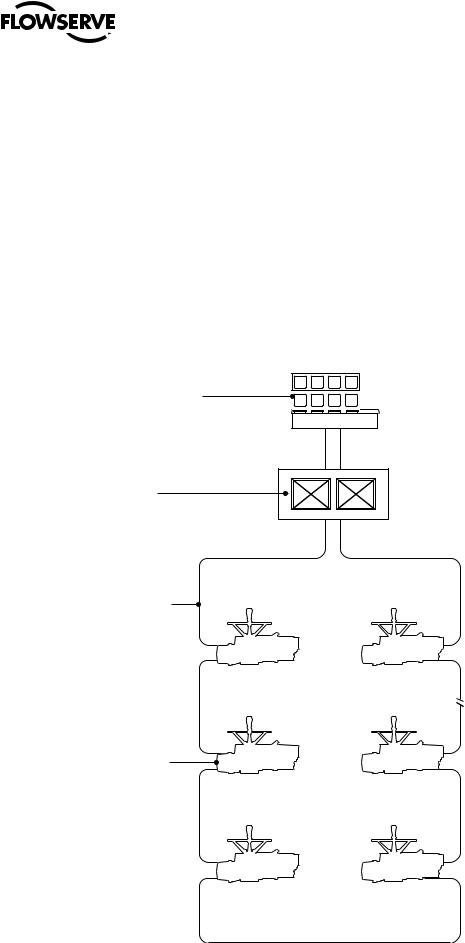
Limitorque’s distributed digital control (DDC) valve control network supports up to 250 actuators over a single twisted-pair cable using Modbus™ protocol. MX actuators and other devices can be accessed from a control room for integration with a plant asset management (PAM) system, distributed control system (DCS), programmable logic controller (PLC), or personal computer (PC) based network. The DDC-100 system consists of a host system, controller, network, and field units. A typical DDC-100 system is shown in Figure 1.1.
Figure 1.1 – Typical DDC-100 system with or without a Master Station II
Host controller
Optional
Master
Station
Network
RS-485
|
1 |
250 |
|
|
. |
|
|
. |
|
|
. |
MX field |
|
|
units |
2 |
5 |
(up to 250) |
6 |
3 |
4 |
|
|

MX/DDC-100 Field Unit Installation and Maintenance FCD LMENIM2329-01 – 03/11
1.6 General Specifications
Direct-to-Host Specifications:
•Direct connection to host controller
•Communicates using the Modbus protocol and the RS-485 electrical standards
•Configurable bitmap
•High-level surge protection on network
Network Specifications:
•Redundant bi-directional loop or daisy chain topology
•Modbus protocol and the RS-485 electrical standards
•High speed—up to 19.2 kbaud communications
MX Field Unit Specifications:
•“OPEN,” “STOP,” and “CLOSE” commands
•“ESD” and “MOVE–TO” position commands
•Actuator status and alarm messages
•Six digital inputs and two analog inputs for user (see Table 2.2, Register Definitions)
•Two surge-protected and mutually isolated communication channels
•MX local control panel configuration
•Torque output (for reference only) and position feedback
•User’s analog input feedback
•Nine digital outputs maximum (three standard/six optional)
Master Station II (Optional) Specifications:
•Supports all Limitorque DDC-100 field units: MX, L120, LY
•Controls up to 250 MOVs
•User-friendly touch panel operator interface:
•Permits configuration and control of DDC-100 network
•Configures communication to host or DCS (Distribution Control System)
•Password protected
•Optional Hot Standby Configuration: Automatically assumes control on Primary Master Failure or on command from the DCS or touch panel
•Provides realtime status of field units through continuous cyclical polling
•Modbus RTU and TCP/IP:
•Addressable
•RS-232/485/422
•10/100 baseT
•Built-in Web server for ease of actuator and network diagnostics
7
flowserve.com
2 |
|
MX/DDC-100 Field Unit Installation and Maintenance FCD LMENIM2329-01 – 03/11 |
|
System Components |
|||
|
|||
|
2.1 |
Introduction |
|
|
This section gives an overview of the components used in the DDC-100 system. The field unit is installed in each MX |
||
|
actuator. The network cable connects the field unit to the network via the actuator terminal block. The network cable is |
||
|
connected to a host controller or Master Station II. |
||
|
2.2 |
Hardware |
|
|
NOTE: Recommended storage procedures are detailed in Bulletin FCD LMENIM2314, MX Maintenance and Spare |
||
|
Parts Manual. Failure to comply with recommended procedures will void the warranty. For longer-term storage, |
||
|
contact Flowserve for procedures and recommendations. |
||
|
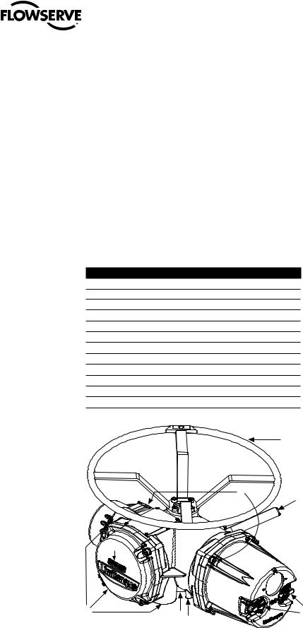
Figure 2.1 – MX-05 actuator |
||
|
Piece |
Description |
|
|
1 |
Handwheel |
|
|
2 |
Declutch Lever |
|
|
3 |
Oil Fills (dotted arrow depicts fill on declutch side) |
|
|
4 |
Controls Compartment (field unit location) |
|
|
5 |
LCD Display |
|
|
6 |
Control Knobs |
|
|
7 |
Ground Lug |
|
|
8 |
Thrust/Torque Base |
|
|
9 |
Conduit Entries |
|
|
10 |
Terminal Compartment |
|
|
11 |
Motor |
|
|
12 |
Nameplate |
|
|
|
1 |
|
|
|
3 |
2 |
|
|
|
|
|
12 |
|
|
|
11 |
|
|
|
10 |
|
|
|
|
|
4 |
|
|
|
5 |
9 |
8 |
7 |
6 |
|
|
8

MX/DDC-100 Field Unit Installation and Maintenance FCD LMENIM2329-01 – 03/11
2.2.1 MX Actuator
The MX is a multi-turn valve actuator designed for operation of ON-OFF and modulating valve applications. This actuator controls the opening and closing of valves. See Figure 2.1.
Features of the MX include:
•Non-intrusive setup
•Separately sealed terminal chamber
•Absolute encoder for valve position sensing (no battery required)
•32-character graphical LCD display with 180° rotation
•Sophisticated electronic control, monitoring, and diagnostic capabilities with LimiGard™ technology
2.2.2 DDC–100 Field Unit
The DDC-100 field unit is installed in the MX controls compartment. This unit permits the actuator to be controlled by a host controller or Master Station II via the DDC-100 network. The field unit includes two high-level, surge-protected, and isolated network communication channels, configurable digital I/O, and configuration via LCD screen. The following commands and information may be transmitted over the DDC-100 network:
•“OPEN,” “STOP,” and “CLOSE” commands
•“ESD” and “MOVE–TO” position commands
•Actuator status and alarm messages
•Six digital inputs and two analog inputs for user (see Table 2.2, Register Definitions)
•Two surge-protected and mutually isolated communication channels
•MX local control panel configuration
•Torque output (for reference only) and position feedback
•User’s analog input feedback
•Nine digital outputs maximum (three standard/six optional)
Figure 2.2 – DDC-100 field unit
9
flowserve.com
MX/DDC-100 Field Unit Installation and Maintenance FCD LMENIM2329-01 – 03/11
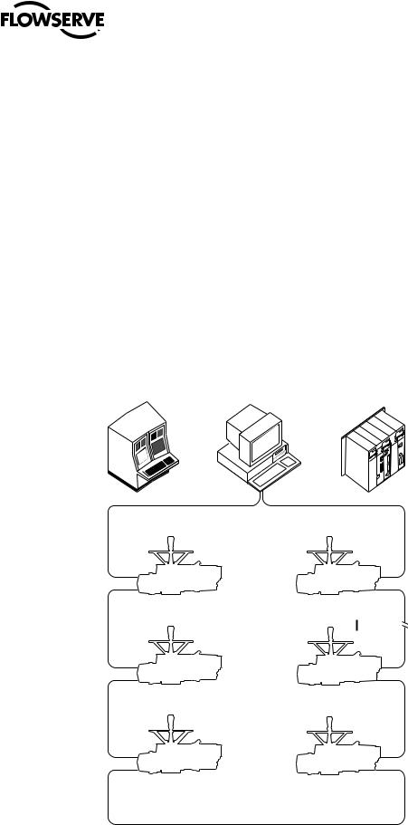
2.2.3 Host Controller
In the DDC-100 system, the network can be connected directly to a host controller without an interposing Master Station II.
In this configuration, the host sends commands and messages to, and gathers responses from, the field units. The commands and messages are sent via RS-485 data signals. The gathered responses are stored in a data table in the host and are periodically updated by sequential polling of the field units. The host controls up to 250 field units. See Section 3.1.2.3, Network Cable Connection to Host System or Master Station II.
When a host controller is used to directly communicate with the field units, i.e., direct-to-host communications, it communicates using the Modbus protocol and the RS-485 electrical standard. This host controller can be one of the following:
•Distributed control system (DCS)
•Programmable logic controller (PLC)
•Personal computer (PC)
•Plant Asset Management (PAM) system
Figure 2.3 – Typical direct-to-host arrangement
DCS |
PC/PAM |
PLC |
1 |
250 |
2 |
5 |
3 |
4 |
10
RS-485
MX/DDC-100 Field Unit Installation and Maintenance FCD LMENIM2329-00 – 2/08
2.2.4 Master Station II
A Master Station II may be used in the DDC-100 system. Master Station II’s are normally located in the control room, and serve as the interface between the field units and the host controller. The following functions are provided:
•Continuous polling of actuator network
•Message routing to/from field units
•Data concentration
•Data logging
In this configuration, the Master Station II receives commands from a host controller. The Master Station II communicates with the host controller using the Modbus Protocol and the RS-232 or RS-485 electrical standard. See Bulletin FCD LMENIM5001, DDC-100 Master Station II Installation and Operation Manual for details.
The Master Station II sends commands and messages to, and gathers responses from, the field units. The commands and messages are sent via RS-485 data signals. The gathered responses are stored in a poll table in the Master Station II and are periodically updated by sequential polling of the field units. The Master Station II controls up to 250 field units. See Section 3.1.2.3, Network Cable Connection to Host System or Master Station II.
Figure 2.4 – Typical Master Station II (rear view)
|
|
10 |
|
1 |
|
2 |
|
|
|
|
|
|
|
|
|
|
|
|
NO SERVICEABLE PARTS INSIDE |
|
|
|
|
|
|
HOT STANDBY |
|
|
SINGLE |
|
|
|
DO NOT USE |
OPTIONAL |
|
|
DO NOT USE |
|
|
|
|
|
|
|
|||
|
WITH 110-240VAC |
|
|
|
|
WITH 110-240VAC |
|
|
EXTERNAL 24VDC |
PRINTER / DEBUG |
ETHERNET |
|
PRINTER / DEBUG |
EXTERNAL 24VDC |
4 |
|
INPUT ONLY |
|
INPUT ONLY |
||||
8 |
+ -- |
|
|
|
|
+ -- |
|
|
24VDC |
|
|
|
|
24VDC |
|
7
MOVE JUMPERS ON INSIDE OF UNIT FOR PROPER OPERATION
l o FUSES
FUSES 2 AMP 250 V
ON
POWER
OFF
INPUT 100-240VAC ~1.5A
|
|
|
|
|
|
|
|
|
MOVE JUMPERS ON |
|
|
|
|
|
|
|
|
|
INSIDE OF UNIT FOR |
DCS |
|
|
|
|
|
|
|
DCS |
PROPER OPERATION |
|
|
|
|
|
|
|
|
||
|
|
|
|
|
|
|
|
FUSES |
|
|
|
|
|
|
|
|
|
2 AMP |
|
|
|
|
|
|
|
|
|
250 V |
FUSES |
|
|
|
|
|
|
|
|
|
|
CHANNEL A |
|
|
CHANNEL B |
ON |
l o |
||||
|
|
POWER |
|||||||
|
|
|
|
|
|
|
|
||
|
|
|
|
|
|
|
|
OFF |
|
|
|
|
|
|
|
|
|
INPUT |
|
|
* |
GND |
|
|
|
* |
GND |
100-240VAC |
|
TA |
DA |
DATA |
|
|
|||||
|
|
|
|
||||||
DATA DA |
|
|
|
|
~1.5A |
|
|||
|
|
|
|
TA |
|
|
|
|
|
9 |
6 |
3 |
1.Ethernet ports
2.Printer/Debug port
3.DCS port
4.Auxiliary 24 VDC power connection
5.Main power switch and connector for 120-240 VAC
6.Electrostatic ground
7.Hot Standby unit main power switch and connector for 120-240 VAC
8.Hot Standby auxiliary 24 VDC power connection
9.Hot Standby DCS Port
10.Hot Standby Printer/Debug Port
5
11
flowserve.com
MX/DDC-100 Field Unit Installation and Maintenance FCD LMENIM2329-01 – 03/11
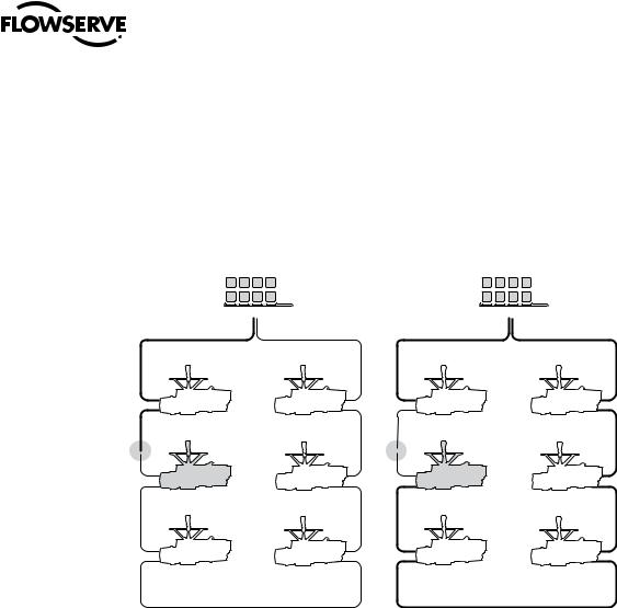
2.2.5 Network Cable
The network consists of a shielded, twisted-pair cable that connects all field units and the host/Master Station II. The cable is normally connected in a loop fashion so that any single break or short will not disable communication.
Figure 2.5 – Redundant connection operation in redundant host loop topology
Signal initiated from host fails to reach |
Instead, signal routes to field unit using |
||||||
field unit which is located after fault... |
other side of the loop cable and |
||||||
|
|
|
|
completes connection. |
|||
|
|
|
|
|
|
|
|
|
|
|
|
|
|
|
|
|
|
|
|
|
|
|
|
|
|
|
|
|
|
|
|
|
|
|
|
|
|
|
|
The network cable connects the field units to the host controller or Master Station II. Belden 3074F, 3105A, or 9841 shielded, twisted-pair cable should be used. The use of other cables may result in a reduction of internodal distances or increased error rate, and is the user’s responsibility.
Belden 3074F Specifications
•Total cable length between repeaters or nodes with repeaters, up to 19.2 kbps: 5000 ft (1.52 km) For loop mode, this is the total length between operating field units. If a field unit loses power, then the relays internal to the field unit connect the A1 Channel to the A2 Channel, which effectively doubles the length of the cable (assuming a single field unit fails). To ensure operation within specifications in the event of power failure to field units, this consideration must be added. Example: To ensure operation within specification when any two consecutive field units lose power, the maximum length of cable, up to 19.2 kbps, should not exceed 5000 ft (1.52 km) per every four field units. See Section 3.1.2.3, Network Cable Connection to Host Controller or Master Station II.
Key Specifications
•Resistance/1000 ft = 18 AWG (7 x 26) 6.92 ohms each conductor (13.84 ohms for the pair)
•Capacitance/ft = 14 pF (conductor-to-conductor)
•Capacitance/ft = 14 pF (conductor-to-shield)
12

MX/DDC-100 Field Unit Installation and Maintenance FCD LMENIM2329-01 – 03/11
Belden 3105A Specifications
•Total cable length between repeaters or nodes with repeaters, up to 19.2 kbps: 4500 ft (1.37 km) For loop mode, this is the total length between operating field units. If a field unit loses power, then the relays internal to the field unit connect the A1 Channel to the A2 Channel, which effectively doubles the length of the cable (assuming a single field unit fails). To ensure operation within specifications in the event of power failure to field units, this consideration must be added. Example: To ensure operation within specification when any two consecutive field units lose power, the maximum length of cable, up to 19.2 kbps, should not exceed 4500 ft (1.37 km) per every four field units. See Section 3.1.2.3, Network Cable Connection to Host Controller or Master Station II.
Key Specifications
•Resistance/1000 ft = 22 AWG (7 x 30) 14.7 ohms each conductor (29.4 ohms for the pair)
•Capacitance/ft = 11.0 pF (conductor-to-conductor)
•Capacitance/ft = 20.0 pF (conductor-to-shield)
Belden 9841 Specifications
•Total cable length between repeaters or nodes with repeaters: up to 19.2 kbps: 3500 ft (1 km) For loop mode, this is the total length between operating field units. If a field unit loses power, then the relays internal to the field unit connect the A1 Channel to the A2 Channel, which effectively doubles the length of the cable (assuming a single field unit fails). To ensure operation within specifications in the event of power failure to field units, this consideration must be added. Example: To ensure operation within specification when any two consecutive field units lose power, the maximum length of cable, up to 19.2 kbps, should not exceed 3500 ft (1 km) per every four field units. See Section 3.1.2.3, Network Cable Connection to Host Controller or Master Station II.
Key Specifications
•Resistance/1000 ft = 24 AWG (7 x 32) 24 ohms each conductor (48 ohms for the pair)
•Capacitance/ft = 12.8 pF (conductor-to-conductor)
•Capacitance/ft = 23 pF (conductor-to-shield)
2.3Software
2.3.1 Modbus Protocol
The Modbus protocol was developed by AEG Modicon® for communicating to various networked devices. The relationship between these devices and a central controller is called a master-slave relationship in which the master (host device) initiates all communication. The slave devices (DDC-100 field units in the actuators) respond to the queries from the master.
Modbus only permits one device to communicate at any given time (simultaneous communication is prohibited) to ensure process control integrity.
13
flowserve.com

MX/DDC-100 Field Unit Installation and Maintenance FCD LMENIM2329-01 – 03/11
2.3.2 Modbus Function Codes
The controlling device (master) must conform to the Modbus protocol as defined in the Modbus-IDA Modbus Application Protocol Specification V1.1a (http://www.Modbus-IDA.org) and support Modbus function codes 01 through 06, 08, 15, and 16. These function codes are a subset of the complete protocol and are defined in Table 2.1.
Table 2.1 – Modbus function codes supported
|
|
Extended |
|
Function |
|
Bit/Register |
Addressing |
Code |
Name |
Addressing |
Range |
01 |
Read Coil Status |
Bit |
0,000 - 9,999 |
02 |
Read Discrete Inputs |
Bit |
10.000 - 19,999 |
03 |
Read Holding Register |
Register |
40,000 - 49,999 |
04 |
Read Input Register |
Register |
30,000 - 39,999 |
05 |
Force Single Coil |
Bit |
0,000 - 9,999 |
06 |
Preset Single Register |
Register |
40,000 - 49,999 |
08 |
Diagnostics |
N/A |
N/A |
15 |
Force Multiple Coils |
Bit |
0,000 - 9,999 |
16 |
Preset Multiple Registers |
Register |
40,000 - 49,999 |
See Table 2.2 for a complete listing of MX/DDC holding registers.
2.3.3 Modbus Function Code 01 (Read Coil Status)
This function code is used to read the coil status in the DDC-100 Field Unit. There are nine coils available to be read on DDC-100 Field Units as shown in Table 2.2. For the MX/DDC, Coil 1 indicates CLOSE contactor and is interlocked with Coil 2, Coil 2 indicates OPEN contactor and is interlocked with Coil 1. When the I/O Module is used in non-MOV (motor-operated valve) mode, relays 1 through 6 or coils 3 through 8 are available for user configuration.
Table 2.2 – DDC-100 coil assignments, Modbus 05 command usage for digital outputs
Coil Number |
Bit Number |
Function |
1 |
00 |
Close/Stop |
2 |
01 |
Open/Stop |
3 |
02 |
S1 or R1 (Opt) Latched |
4 |
03 |
S2 or R2 (Opt) Latched |
5 |
04 |
R3 (Opt) Latched |
6 |
05 |
R4 (Opt) Latched |
7 |
06 |
R5 (Opt) Latched |
8 |
07 |
R6 (Opt) Latched |
9 |
08 |
R7 (Opt) Latched |
10 |
09 |
R8 (Opt) Latched |
The normal response to the (05) command is an echo of the command.
Example
Poll field unit number 3 for 8 coils starting at coil 1.
Query: 0301000000083C2E
Response: 03010118503A
14

MX/DDC-100 Field Unit Installation and Maintenance FCD LMENIM2329-01 – 03/11
Message Breakdown
Query |
|
|
|
Response |
|
|
03 |
|
Slave (Field Unit) Address |
|
03 |
|
Slave (Field Unit) Address |
|
|
|
||||
|
|
|
|
|
|
|
01 |
|
Function |
|
01 |
|
Function |
|
|
|
|
|
|
|
00 |
|
Starting Address Hi |
|
01 |
|
Byte Count |
|
|
|
|
|
|
|
00 |
|
Starting Address Lo |
|
181 |
|
Data (Coils 8 - 1) |
00 |
|
No. of Points Hi |
|
503A |
|
Error Check (CRC) |
|
|
|
|
|
|
|
08 |
|
No. of Points Lo |
|
|
|
|
|
|
|
|
|
|
|
3C2E |
|
Error Check (CRC) |
|
|
|
|
|
|
|
|
|
|
|
Note 1: 18h equals 00011000 or coils 4 and 5 are ON.
2.3.4 Modbus Function Code 02 (Read Input Status)
This function code is used to read the discrete input status bits in the DDC-100 Field Unit. The use of this function code will provide the user with the input status bits that are used to develop holding registers 9 through 13. The status bit inputs are contained in locations 10129-10208 for each DDC-100 Field Unit and are defined in Table 2.3.
Table 2.3 – Status Bit Definitions
|
Modbus |
|
|
|
Bit Number |
Bit |
MX/DDC |
|
|
|
Address |
|
|
|
129 |
|
Opened |
|
|
128 |
|
|||
|
|
|
|
|
130 |
129 |
Closed |
|
|
|
|
|
|
|
131 |
130 |
Stopped in mid-travel |
|
|
|
|
|
|
|
132 |
131 |
Opening |
|
|
|
|
|
|
|
133 |
132 |
Closing |
|
|
|
|
|
|
|
134 |
133 |
Valve jammed |
|
|
|
|
|
|
|
135 |
134 |
Not in remote |
|
|
|
|
|
|
|
136 |
135 |
Combined fault |
|
|
|
|
|
|
|
137 |
136 |
Over-temperature fault |
|
|
|
|
|
|
|
138 |
137 |
Actuator failing to de-energize |
|
|
|
|
|
|
|
139 |
138 |
Channel A fault |
|
|
|
|
|
|
|
140 |
139 |
Channel B fault |
|
|
|
|
|
|
|
141 |
140 |
Open torque switch fault |
|
|
|
|
|
|
|
142 |
141 |
Close torque switch fault |
|
|
|
|
|
|
|
143 |
142 |
Valve operated manually fault |
|
|
|
|
|
|
|
144 |
143 |
Phase error |
|
|
|
|
|
|
|
145 |
144 |
Open inhibit active |
|
|
|
|
|
|
|
146 |
145 |
Close inhibit active |
|
|
|
|
|
|
|
147 |
146 |
Not used |
|
|
|
|
|
|
|
148 |
147 |
Not used |
|
|
|
|
|
|
|
149 |
148 |
One or more phases is missing |
|
|
|
|
|
|
|
150 |
149 |
Reverse phase sequence is occurring |
|
|
|
|
|
|
|
151 |
150 |
ESD conflict |
|
|
|
|
|
|
|
152 |
151 |
Inhibit conflict |
|
|
|
|
|
|
|
153 |
152 |
Use in local/stop (input must be set for CSE and enabled) |
15 |
|
|
|
|
||
154 |
153 |
Not used |
||
|
||||
|
|
|
|
|
155 |
154 |
Network emergency shutdown (ESD) is active |
|
|
|
|
|
|
|
156 |
155 |
Local emergency shutdown is active |
|
|
|
|
|
|
flowserve.com

MX/DDC-100 Field Unit Installation and Maintenance FCD LMENIM2329-01 – 03/11
Table 2.3 – Status Bit Definitions (continued)
|
|
Modbus |
|
|
Bit Number |
Bit |
MX/DDC |
|
|
Address |
|
|
157 |
|
Field unit microprocessor has reset since the last poll |
|
156 |
||
|
|
|
|
|
158 |
157 |
MX in stop move |
|
|
|
|
|
159 |
158 |
Opening in local mode |
|
|
|
|
|
160 |
159 |
Closing in local mode |
|
|
|
|
|
161 |
160 |
Close contactor (interlocked) |
|
|
|
|
|
162 |
161 |
Open contactor (interlocked) |
|
|
|
|
|
163 |
162 |
S1 or R1 (opt) |
|
|
|
|
|
164 |
163 |
S2 or R2 (opt) |
|
|
|
|
|
165 |
164 |
R3 (opt) |
|
|
|
|
|
166 |
165 |
R4 (opt) |
|
|
|
|
|
167 |
166 |
R5 (opt) |
|
|
|
|
|
168 |
167 |
R6 (opt) |
|
|
|
|
|
169 |
168 |
R7 (opt) |
|
|
|
|
|
170 |
169 |
Network relay |
|
|
|
|
|
171 |
170 |
R8 (opt) |
|
|
|
|
|
172 |
171 |
Not used |
|
|
|
|
|
173-176 |
172-175 |
Mov series (0=1, A=9) |
|
|
|
|
|
177 |
176 |
Remote switch |
|
|
|
|
|
178 |
177 |
Thermal overload |
|
|
|
|
|
179 |
178 |
Open torque switch |
|
|
|
|
|
180 |
179 |
Open limit switch |
|
|
|
|
|
181 |
180 |
Close torque switch |
|
|
|
|
|
182 |
181 |
Close limit switch |
|
|
|
|
|
183 |
182 |
Not used |
|
|
|
|
|
184 |
183 |
Not used |
|
|
|
|
|
185 |
184 |
User Input 0 |
|
|
|
|
|
186 |
185 |
User Input 1 |
|
|
|
|
|
187 |
186 |
User Input 2 |
|
|
|
|
|
188 |
187 |
Remote stop input |
|
|
|
|
|
189 |
188 |
Remote open input |
|
|
|
|
|
190 |
189 |
Remote close input |
|
|
|
|
|
191 |
190 |
Not used |
|
|
|
|
|
192 |
191 |
Not used |
|
|
|
|
|
193 |
192 |
Analog board 1 present |
|
|
|
|
|
194 |
193 |
Analog board 2 present |
|
|
|
|
|
195 |
194 |
Analog Input #1 lost |
|
|
|
|
|
196 |
195 |
Analog Input #2 lost |
|
|
|
|
|
197 |
196 |
Network Channels A/B timed out |
|
|
|
|
|
198 |
197 |
Relay board R5-R8 present |
|
|
|
|
|
199 |
198 |
DDC board present |
|
|
|
|
16 |
200 |
199 |
Relay board R1-R4 and RM present |
|
|
|
|
201 |
200 |
FF board present |
|
|
|
|
|
|
202 |
201 |
PB PA board present |
|
|
|
|
|
203 |
202 |
CLE assigned for input 2 |
|
|
|
|
|
204 |
203 |
DNET board present |
|
|
|
|

MX/DDC-100 Field Unit Installation and Maintenance FCD LMENIM2329-01 – 03/11
Table 2.3 – Status Bit Definitions (continued)
Modbus
Bit Number Bit MX/DDC
Address
205204 Lost Phase Input
206205 Phase Reverse Input
207 |
206 |
Not used |
|
|
|
208 |
207 |
PB DP board present |
Example
Poll field unit number 22 for 16 inputs starting at input 129 with the actuator opening.
Query: 1602008000107B09
Response: 1602020108CDED
Message Breakdown
Query |
|
|
|
Response |
|
|
16 |
|
Slave (Field Unit) Address |
|
16 |
|
Slave (Field Unit) Address |
|
|
|
||||
|
|
|
|
|
|
|
02 |
|
Function |
|
02 |
|
Function |
|
|
|
|
|
|
|
00 |
|
Starting Address Hi |
|
02 |
|
Byte Count |
|
|
|
|
|
|
|
80 |
|
Starting Address Lo |
|
011 |
|
Data (Inputs 10136 - 10129) |
00 |
|
No. of Points Hi |
|
082 |
|
Data (Inputs 10144 - 10137) |
10 |
|
No. of Points Lo |
|
CDED |
|
Error Check (CRC) |
|
|
|
|
|
|
|
7B09 |
|
Error Check (CRC) |
|
|
|
|
|
|
|
|
|
|
|
Note 1: 01h equals 0000 0001 (actuator open input bit is ON).
Note 2: 08h equals 0000 1000 (actuator Channel B Fail bit is ON).
2.3.5 Modbus Function Code 03 (Read Holding Register)
This function code is used to read the binary contents of holding registers in the DDC-100 Field Unit. This function code is typically used during the network polling cycle. A network poll should consist of field unit registers 9 (Status) and 10 (Fault) as a minimum. Holding register 8 should also be polled when the actuator is configured for the analog feedback option or position control. See Table 2.4 for a complete listing of the holding registers.
17
flowserve.com

MX/DDC-100 Field Unit Installation and Maintenance FCD LMENIM2329-01 – 03/11
Table 2.4 – Register definitions
Register # |
Description |
Meaning |
|
|
1 |
Command |
Registers 1 and 2 are write-only registers used for Modbus |
||
|
|
Function Code 06 |
|
|
2 |
Argument |
Registers 1 and 2 are write-only registers used for Modbus |
||
|
|
Function Code 06 |
|
|
3 |
Analog Output 1 |
Analog Output 1 Value (Default 0-100)1 |
||
4 |
Analog Output 2 |
Analog Output 2 Value (Default 0-100)1 |
||
5 |
Analog Input |
Main Power (Volts) |
|
|
6 |
Analog Input |
Analog Input 1 (Default 0-100)1 |
User 4-20 mA / 0-20 mA Input |
|
7 |
Analog Input |
Analog Input 2 (Default 0-100)1 |
User 4-20 mA / 0-20 mA Input |
|
8 |
Position |
Valve Position, Scaled Value (Default 0-100)1 |
||
9 |
Status Register |
16 Bits of field unit status: |
|
|
|
|
Bit 0 Opened |
|
|
|
|
Bit 1 |
Closed |
|
|
|
Bit 2 |
Stopped in Mid-Travel |
|
|
|
Bit 3 |
Opening |
|
|
|
Bit 4 |
Closing |
|
|
|
Bit 5 Valve jammed |
|
|
|
|
Bit 6 |
Not in Remote2 |
|
|
|
Bit 7 |
Combined fault3 |
|
|
|
Bit 8 |
Over temperature fault |
|
|
|
Bit 9 |
Future Implementation |
|
|
|
Bit 10 |
Network Channel A fault4 (Terminals 5 and 4) |
|
|
|
Bit 11 |
Network Channel B fault4 (Terminals 13 and 14) |
|
|
|
Bit 12 |
Open torque switch fault |
|
|
|
Bit 13 |
Close torque switch fault |
|
|
|
Bit 14 |
Valve-operated manually fault |
|
|
|
Bit 15 |
Phase error |
|
Note 1: Default value is scaled 0-100 of span. Changes made to “Analog Scale” affect analog registers (3, 4, 6, 7, 8) and “move-to” commands. (0-100, 0-255, 0-4095)
Note 2: MX/DDC actuators shipped after 2nd QTR, 1999, have the following definition of Register 9 Bit 6. When this bit has a value of 1 or true, the actuator is in LOCAL or STOP (unavailable for network control). The actuator selector switch in REMOTE (available for network control) is indicated by Register 12 Bit 0 having a value of 1 or true.
IMPORTANT: Verify host program when installing an MX/DDC actuator shipped after 2nd QTR, 1999, on a network commissioned before 2nd QTR, 1999, for proper indication of selector switch values. Failure to verify proper selector switch indication at the host may cause unsafe conditions at the facility.
MX/DDC actuators shipped prior to 2nd QTR, 1999, have the following definition for Register 9 Bit 6. When this bit has a value of 1 or true, the actuator selector switch is in LOCAL mode. This bit does not indicate STOP or REMOTE. The actuator selector switch in REMOTE (available for network control) is indicated by Register 12 Bit 0 having a value of 1 or true. Register 9 Bit 6 value 0 (zero) or false AND Register 12 Bit 0 value 0 (zero) or false indicates selector switch is in the STOP position.
Note 3: Combined Fault bit is high when Bit 5 or 8 or 9 or 15 or (Bits 10 and 11) is high.
Note 4: Channel A is physical connection A1. Channel B is physical connection A2. (See Appendix A.)
18

MX/DDC-100 Field Unit Installation and Maintenance FCD LMENIM2329-01 – 03/11
Table 2.4 – Register definitions (continued)
Register # |
Description |
Meaning |
|
10 |
Fault Register |
16 Bits of field status |
|
|
|
Bit 0 |
Open inhibit active |
|
|
Bit 1 |
Close inhibit active |
|
|
Bit 2 |
Not Used |
|
|
Bit 3 |
Not Used |
|
|
Bit 4 |
One or more phases are missing |
|
|
Bit 5 |
Reverse phase sequence is occurring |
|
|
Bit 6 |
ESD conflict |
|
|
Bit 7 |
Inhibit conflict |
|
|
Bit 8 |
CSE in local/stop (input must be set for CSE and enabled) |
|
|
Bit 9 |
Not Used |
|
|
Bit 10 |
Network emergency shutdown is active |
|
|
Bit 11 |
Local PB emergency shutdown is active |
|
|
Bit 12 |
Field unit microprocessor has reset since the last poll |
|
|
Bit 13 MX in stop mode |
|
|
|
Bit 14 |
Opening in local mode |
|
|
Bit 15 |
Closing in local mode |
11 |
Digital Outputs |
Value of 16 Digital Outputs |
|
|
|
Bit 0 |
Close contactor (Interlocked) |
|
|
Bit 1 |
Open contactor (Interlocked) |
|
|
Bit 2 |
S1 or R1 (Opt) |
|
|
Bit 3 |
S2 or R2 (Opt) |
|
|
Bit 4 |
R3 (Opt) |
|
|
Bit 5 |
R4 (Opt) |
|
|
Bit 6 |
R5 (Opt) |
|
|
Bit 7 |
R6 (Opt) |
|
|
Bit 8 |
R7 (Opt) |
|
|
Bit 9 |
Network Relay |
|
|
Bit 10 |
R8 (Opt) |
|
|
Bit 11 |
Not Used |
|
|
BIT 12-15 MOV Series (0 = 1, A = 9) |
|
12 |
Digital Inputs 1 |
Value of 16 Digital Inputs |
|
|
|
Bit 0 Remote Switch |
|
|
|
Bit 1 |
Thermal Overload |
|
|
Bit 2 |
Open Torque Switch |
|
|
Bit 3 |
Open Limit Switch |
|
|
Bit 4 |
Close Torque Switch |
|
|
Bit 5 |
Close Limit Switch |
|
|
Bit 6 |
Not Used |
|
|
Bit 7 |
Not Used |
|
|
Bit 8 |
User Input 0 (Default=ESD), Terminal 30 |
|
|
Bit 9 |
User Input 1 (Default=Open Inhibit), Terminal 34 |
|
|
Bit 10 |
User Input 2 (Default=Close Inhibit), Terminal 35 |
|
|
Bit 11 |
Remote Stop Input, Terminal 26 |
|
|
Bit 12 |
Remote Open Input, Terminal 25 |
|
|
Bit 13 |
Remote Close Input, Terminal 27 |
|
|
Bits 14-15 Not Used |
|
19
flowserve.com

MX/DDC-100 Field Unit Installation and Maintenance FCD LMENIM2329-01 – 03/11
Table 2.4 – Register definitions (continued)
Register # |
Description |
Meaning |
|
|
13 |
Digital Inputs 2 |
Value of 16 Digital Inputs |
||
|
|
Bit 0 Analog board 1 present |
||
|
|
Bit 1 Analog board 2 present |
||
|
|
Bit 2 |
Analog Input 1 lost |
|
|
|
Bit 3 |
Analog Input 2 lost |
|
|
|
Bit 4 |
Network Channels A/B timed out |
|
|
|
Bit 5 |
Relay board R5-R8 present |
|
|
|
Bit 6 |
DDC board present |
|
|
|
Bit 7 Relay board R1-R4 and RM present |
||
|
|
Bit 8 |
Foundation Fieldbus board present |
|
|
|
Bit 9 |
Profibus PA board present |
|
|
|
Bit 10 |
CSE chosen for input 2 |
|
|
|
Bit 11 |
DeviceNet board present |
|
|
|
Bit 12 |
Phase lost |
|
|
|
Bit 13 |
Phase reverse |
|
|
|
Bit 14 |
Not Used |
|
|
|
Bit 15 |
Profibus DP board present |
|
14 |
Timers and Analog Channels |
Internal compartment temperature1 |
||
15 |
User Faults |
Bits 0-15 |
Not Used |
|
16 |
Current State |
Bits 0-15 |
Not Used |
|
17 |
Field Unit Holding Register |
Special Applications Only |
||
18 |
Field Unit Holding Register |
Special Applications Only |
||
19 |
Field Unit Holding Register |
Special Applications Only |
||
20 |
Field Unit Holding Register |
Special Applications Only |
||
21 |
Field Unit Holding Register |
Special Applications Only |
||
22 |
Field Unit Holding Register |
Special Applications Only |
||
23 |
Field Unit Holding Register |
Special Applications Only |
||
24-44 |
Reserved |
Special Applications Only |
||
45-47 |
Not Named |
Special Applications Only |
||
48 |
TP_START_POSITION |
Special Applications Only |
||
49 |
TP_STOP_POSITION |
Special Applications Only |
||
50 |
TP_SAMPLE |
Special Applications Only |
||
51 |
TP_MID_T_HIGH |
Special Torque Applications Only |
||
52 |
TP_MID_T_POS |
Special Applications Only |
||
53 |
TP_MID_T_AV_VAL |
Special Torque Applications Only |
||
54 |
TP_STOP_VAL |
Special Applications Only |
||
55 |
TP_BEFORE_ MID_T_HIGH |
Special Torque Applications Only |
||
56 |
TP_AFTER_ MID_T_HIGH |
Special Torque Applications Only |
||
Note 1: Range is +90°C to -55°C. High byte 00 indicates positive (+) and 01 indicates negative (-). Low byte indicates temperature value.
Example: 0x0019 = +25°C 0x011E = -30°C
Example
Poll field unit number 125 for 3 registers starting at register 8 with the actuator stopped between the limits and in local mode.
Query: 7D0300070003BFF6
Response: 7D0306003D084400003E07
20
 Loading...