


|
USER INSTRUCTIONS |
Limitorque MX |
Maintenance |
Electronic Actuator |
and Spare Parts |
FCD LMENIM2314-00 – 07/08 |
|
|
|
Experience In Motion

Limitorque MX Maintenance and Spare Parts FCD LMENIM2314-00 – 07/08
Contents
1 |
Introduction |
1 |
|
|
|
|
|
|
|
|
|
1.1 Premise |
1 |
|
|
|
1.2 Procedure Emphasis |
1 |
|
|
|
|
|
|
|
|
1.3 Important Notes and Warning Statements |
1 |
|
|
|
|
|
|
|
|
1.4 Reference Documents |
2 |
|
|
2 |
MX Actuator Subassembly |
3 |
|
|
|
|
|
|
|
|
2.1 MX Actuator Subassembly Components |
4 |
|
|
|
|
|
|
|
|
2.1.1 Product Description |
4 |
|
|
|
2.1.2 Storage |
4 |
|
|
|
|
|
|
|
|
2.1.3 Unit Weights |
5 |
|
|
|
|
|
|
|
|
2.2 Product Identification |
5 |
|
|
|
2.2.1 Initial Inspection and Recording Suggestions |
5 |
|
|
|
|
|
|
|
|
2.3 Maintenance |
6 |
|
|
|
|
|
|
|
|
2.3.1 Recommended Maintenance |
6 |
|
|
|
2.3.2 Unit Lubrication |
6 |
|
|
|
|
|
|
|
|
2.3.3 O-Ring and Lubrication |
8 |
|
|
|
|
|
|
|
|
2.4 Subassembly Removal and Remounting Procedures |
8 |
|
|
|
2.5 How to Order Replacement Subassemblies |
9 |
|
|
|
|
|
|
|
|
2.5.1 Replacement Parts |
9 |
|
|
|
|
|
|
|
|
2.5.2 Return Procedure |
9 |
|
|
3 Remove Actuator from Mounting Adapter |
11 |
|
|
|
|
|
|
|
|
|
3.1 Actuator Removal with Type B1/B4/B4E Base (Torque) |
11 |
|
|
|
|
|
|
|
|
3.1.1 Removal (Type B1/B4/B4E Base) |
11 |
|
|
|
3.1.2 Remounting (Type B1/B4/B4E Base) |
12 |
|
|
|
|
|
|
|
|
3.2 Actuator Removal with Type A1/A1E Base (Thrust) |
14 |
|
|
|
|
|
|
|
|
3.2.1 Removal (Type A1/A1E Base) Actuator Removal Separate from Thrust Base |
14 |
|
|
|
3.2.2 Remounting (Type A1/A1E Base) Actuator Remounting Separate from Thrust Base |
15 |
|
|
|
|
|
|
|
|
3.2.3 Removal (Type A1/A1E Base) Actuator and Thrust Base as a Unit |
17 |
|
|
|
|
|
|
|
|
3.2.4 Remounting (Type A1/A1E Base) Actuator and Thrust Base as a Unit |
18 |
|
|
4 |
Mechanical Assemblies |
19 |
|
|
|
|
|
|
|
|
4.1 Motor |
19 |
|
|
|
|
|
|
|
|
4.1.1 Removal |
20 |
|
|
|
4.1.2 Remounting |
21 |
|
|
|
|
|
|
|
|
4.1.3 Removal and mounting of MX-140 motor (40 RPM and greater) |
22 |
|
|
|
|
|
|
|
|
4.1.4 Remounting |
23 |
|
|
|
4.1.5 Mounting of MX-150 motor |
23 |
|
|
|
|
|
|
|
|
4.2 Declutch |
25 |
|
|
|
|
|
|
|
|
4.2.1 Removal |
27 |
|
|
|
4.2.2 Remounting |
29 |
|
|
|
|
|
|
|
|
4.3 Top-Mounted Handwheel (MX-05, -10, -20, and -40) |
32 |
|
|
|
|
|
|
|
|
4.3.1 Removal |
33 |
|
|
|
4.3.2 Remounting |
33 |
|
|
|
|
|
|
|
|
4.4 Side-Mounted Handwheel Without Spur Gear Attachment (MX-10, -20, -85, -140, and -150) |
35 |
i |
|
|
|
|
|
|
|
4.4.1 Side-Mounted Handwheel Without Spur Gear Attachment (MX-85, -140, and -150) |
36 |
|
|
|
4.4.2 Removal of Side-Mounted Handwheel (MX-10, -20, -85, -140, and -150) |
37 |
|
|
|
|
|
|
|
|
4.4.3 Removal |
37 |
|
|
|
|
|
|
|
|
4.4.4 Remounting |
39 |
|
flowserve.com

Limitorque MX Maintenance and Spare Parts FCD LMENIM2314-00 – 07/08
4.5 Side-Mounted Handwheel With Spur Gear Attachment (MX-40, -85, -140, and -150) |
40 |
|
|
4.5.1 MX-85, -140, and -150 Handwheel with SGA |
41 |
|
|
4.5.2 Removal of Handwheel |
42 |
4.5.3 Removal |
42 |
|
|
4.5.4 Remounting |
45 |
|
|
4.6 Converting Top-Mounted Handwheel to Side-Mounted Handwheel (MX-10, -20, and -40) |
50 |
4.6.1 Removing Top-Mounted Handwheel |
50 |
|
|
4.6.2 Installing Side-Mounted Handwheel |
51 |
|
|
4.7 Thrust Base Type A1/A1E |
53 |
4.7.1 Removal |
56 |
|
|
4.7.2 Remounting |
56 |
|
|
4.8 Torque Base Type B1 |
57 |
4.8.1 Removal |
58 |
|
|
4.8.2 Remounting |
58 |
|
|
4.9 Baseplate Type B4 |
59 |
4.9.1 Removal |
60 |
|
|
4.9.2 Remounting |
62 |
|
|
4.10 Worm Shaft |
63 |
4.10.1 Removal |
64 |
|
|
4.10.2 Remounting |
65 |
|
|
4.11 Drive Sleeve (MX-05 and -10) |
67 |
4.11.1 Removal |
68 |
|
|
4.11.2 Remounting |
69 |
|
|
4.12 Drive Sleeve (MX-20, -40, -85, -140, and -150) |
70 |
4.12.1 Removal |
71 |
|
|
4.12.2 Remounting |
73 |
|
|
4.12.3 MX-85, -140, and -150 Optional Drive Sleeve and Baseplate Removal |
74 |
4.12.4 MX-85, -140, and -150 Optional Drive Sleeve and Baseplate Remounting |
76 |
|
|
4.13 Handwheel Adapter (MX-05) |
77 |
|
|
4.13.1 Removal |
78 |
4.13.2 Remounting |
79 |
|
|
4.14 Handwheel Adapter (MX-10, -20 and -40)/Handwheel Worm Gear (MX-10, -20, -40, -85, -140, and -150) |
81 |
|
|
4.14.1 Removal |
83 |
4.14.2 Remounting |
84 |
|
|
4.15 Clutch and Clutch Ring Components (MX-20, -40, -85, -140, and -150) |
87 |
|
|
4.15.1 Removal |
88 |
4.15.2 Remounting |
89 |
|
|
5 Electronic Assemblies |
93 |
|
|
5.1 Control Panel (CP) |
93 |
5.2 Control Module |
94 |
|
|
5.2.1 Removal |
95 |
|
|
5.2.2 Remounting |
98 |
5.2.3 Fuse Replacement |
101 |
|
|
5.2.4 Control Module Return Options |
102 |
|
|
5.2.5 EPROM Care and Replacement |
102 |
ii

Limitorque MX Maintenance and Spare Parts FCD LMENIM2314-00 – 07/08
5.3 Installation and Removal of SMT Controls |
|
(most units supplied after September 2003 and before September 2007) |
105 |
|
|
5.3.1 Installation |
105 |
5.3.2 Removal |
108 |
|
|
5.3.3 Fuse Replacement |
108 |
|
|
5.3.4 Control Module Return Options |
108 |
5.4 Mounting of SMT Controls with 54-point terminal block and four LED configuration |
|
(some units supplied from December 2006 with majority after September 2007) |
109 |
|
|
5.4.1 Installation |
109 |
5.4.2 Removal |
110 |
|
|
5.5 Mounting of Standard and Optional Controls with 54-point terminal block and four LED configuration |
111 |
|
|
5.5.1 Installation |
111 |
5.5.2 Removal |
114 |
|
|
5.6 Adding Electronic Options to Your MX Actuator(Most Supplied After September 2007) |
114 |
|
|
5.7 Restoring Power to Actuator with New Control Module |
115 |
5.8 Terminal Block (prior to March 2007) |
115 |
|
|
5.8.1 Removal |
116 |
|
|
5.8.2 Remounting |
118 |
5.9 MX Terminal Block (Supplied With Most Actuators Since March 2007) |
120 |
|
|
5.9.1 Terminal Block Shield Installation |
120 |
|
|
5.10 Control Module-Contactor Assembly (Not required for most actuators shipped after September 2007. |
|
Please see Section 5.4 for power board installation with contactor.) |
121 |
|
|
5.10.1 Removal |
122 |
|
|
5.10.2 Remounting |
123 |
5.11 Replacing 19 Amp Reverser on the MX-140 and -150 (Not for most actuators shipped after September 2007) |
125 |
|
|
5.12 19 Amp Power Assembly for Units Shipped After September 2007 |
128 |
|
|
5.13 Encoder (Through hole and surface mount technology, most units prior to September 2007) |
129 |
5.13.1 Removal |
130 |
|
|
5.13.2 Remounting |
132 |
|
|
5.14 Encoder Drive Cartridge (Most units prior to September 2007) |
133 |
5.14.1 Removal |
134 |
|
|
5.14.2 Remounting |
135 |
|
|
5.15 Removal and Replacement of MX Encoder (Supplied With Most Actuators Since September 2007) |
136 |
5.15.1 Removal |
137 |
|
|
5.15.2 Remounting |
137 |
|
|
5.16 Encoder Drive Cartridge (Supplied With Most Actuators Since September 2007) |
138 |
5.16.1 Removal |
139 |
|
|
5.16.2 Remounting |
140 |
|
|
5.17 Motor Lead Harness (MX-85, -140, and -150) |
141 |
5.17.1 Removal |
141 |
|
|
5.17.2 Remounting |
142 |
|
|
5.18 Solid State Motor Reverser Upgrade Instructions (Most units prior to September 2007) |
143 |
5.18.1 Disassembly Procedure |
144 |
|
|
5.18.2 Assembly Procedure |
145 |
|
|
5.19 Mounting of SSMR (Solid State Motor Reverser) in units shipped after February 2008 |
147 |
5.20 Complete Conversion to SMT Controls |
149 |
|
|
iii
flowserve.com

Limitorque MX Maintenance and Spare Parts FCD LMENIM2314-00 – 07/08
6 Spare and Replacement Parts |
150 |
|
|
6.1 Guidelines for Recommended Spare Parts |
150 |
|
|
6.1.1 Wear Components |
150 |
6.1.2 Bearings, O-rings, and Seals |
150 |
|
|
6.1.3 Critical Components |
151 |
|
|
6.2 Recommended Spare Parts for MX Actuators |
151 |
6.2.1 Commissioning and Startup |
151 |
|
|
6.2.2 Short-Term Duty |
151 |
|
|
6.2.3 Long-Term Duty |
151 |
6.2.4 Severe Duty |
152 |
|
|
6.3 Other Concerns |
152 |
|
|
7 Regulatory Information |
154 |
7.1 Declaration of Conformity |
154 |
|
|
Figures
|
Figure 2.1 – Typical MX Actuator |
3 |
|
|
|
|
Figure 2.2 – MX Nameplate |
5 |
|
|
|
|
Figure 2.3 – Oil Fill/Plug Locations (MX-05 through -40) |
7 |
|
|
|
|
Figure 2.4 – Oil Fill and Drain Locations (MX-85, -140, and -150) |
7 |
|
|
|
|
Figure 4.1 – Motor (MX-05, -10, -20, and -40) |
19 |
|
|
|
|
Figure 4.3 – Motor, Support Plate and Adapter (MX-150) |
24 |
|
|
|
|
Figure 4.4 – Declutch (MX-05 and -10) |
25 |
|
|
|
|
Figure 4.5 – Declutch (MX-20 and -40) |
26 |
|
|
|
|
Figure 4.6 – Declutch (MX-85, -140, and -150) |
27 |
|
|
|
|
Figure 4.7 – Top-Mounted Handwheel (MX-05, -10, -20, and -40) |
32 |
|
|
|
|
Figure 4.8 – Side-Mounted Handwheel (MX-10 and -20) |
35 |
|
|
|
|
Figure 4.9 – Side-Mounted Handwheel (MX-85, -140, and -150) |
36 |
|
|
|
|
Figure 4.10 – Side-Mounted Handwheel with SGA (MX-40) |
40 |
|
|
|
|
Figure 4.11 – Side-Mounted Handwheel With SGA (MX-85, -140, and -150) |
41 |
|
|
|
|
Figure 4.12 – Type A1 Thrust Base (MX-05, -10, -20, and -40) |
53 |
|
|
|
|
Figure 4.13 – Type A1 Thrust Base (MX-85) - F16 Flange |
54 |
|
|
|
|
Figure 4.14 – Type A1 Thrust Base (MX-85, -140, and -150) - F25 Flange |
55 |
|
|
|
|
Figure 4.15 – Type B1 Torque Base (MX-05, -10, -20, and -40) |
57 |
|
|
|
|
Figure 4.16 – Type B4 Baseplate (MX-05, -10, -20, and -40) |
59 |
|
|
|
|
Figure 4.17 – Type B4 Baseplate (MX-85, -140, and -150) |
60 |
|
|
|
|
Figure 4.18 – Worm Shaft (MX-05, -10, -20, and -40) |
63 |
|
|
|
|
Figure 4.19 – Drive Sleeve (MX-05 and -10) |
67 |
|
|
|
|
Figure 4.20 – MX-20 and -40 Drive Sleeve |
70 |
|
|
|
|
Figure 4.21 – MX-85, -140, and -150 10:1 and 13:1 ratios |
71 |
|
|
|
|
Figure 4.22 – Handwheel Adapter (MX-05) |
77 |
|
|
|
iv |
Figure 4.23 – Handwheel (MX-05) |
77 |
|
|
|
Figure 4.24 – Handwheel Adapter Assembly |
81 |
|
|
|
|
|
Figure 4.25 – Handwheel Worm Gear Assembly |
82 |
|
|
|
|
Figure 4.26 – MX-20 and -40 Clutch and Ring Components |
87 |
|
|
|
|
Figure 4.27 – MX-85, -140, and -150 Clutch and Ring Components |
87 |
|
|
|

Limitorque MX Maintenance and Spare Parts FCD LMENIM2314-00 – 07/08
Figure 4.28 – MX-85, -140, and -150 Clutch Ring |
90 |
|
|
Figure 5.1 – Control Panel |
93 |
|
|
Figure 5.2 – Control Module |
94 |
Figure 5.3 – Location of Fuses and Voltage Jumper |
101 |
|
|
Figure 5.4 – LCS Board |
102 |
|
|
Figure 5.5 – Main CPU Board |
102 |
Figure 5.6 – Power Board |
103 |
|
|
Figure 5.7 – DDC Board |
103 |
|
|
Figure 5.8 – Location of Fuses and Voltage Jumper |
108 |
Figure 5.9 – SMT Controls with four LEDs |
109 |
|
|
Figure 5.10 – Option Board Assembly |
113 |
|
|
Figure 5.11 – Restoring Power to Actuator with New Control Module |
115 |
Figure 5.12 – Terminal Block |
116 |
|
|
Figure 5.13 – Terminal Block |
120 |
|
|
Figure 5.14 – Terminal Block Shield |
120 |
Figure 5.15 – Control Module - Contactor Assembly and Wiring Diagrams |
121 |
|
|
Figure 5.15 – (continued) |
122 |
|
|
Figure 5.16 – Encoder |
130 |
Figure 5.17 – Encoder Drive Cartridge |
133 |
|
|
Figure 5.18 – Encoder |
136 |
|
|
Figure 5.19 – Encoder Drive Cartridge |
138 |
Figure 5.20 – Motor Lead Assembly |
141 |
|
|
Figure 5.21 – Cutaway View of SSMR Controls Area |
143 |
|
|
Figure 5.22 – Disassembly Procedure |
144 |
Figure 5.23 – Solid State Reverser and Fuse Block Assembly Installation |
145 |
|
|
Figure 5.24 – Control module reinstallation |
146 |
|
|
Figure 5.25 – SSMR (Solid State Motor Reverser) |
148 |
Tables
Table 2.1 – MX Actuator Subassembly Components |
4 |
|
||
|
|
|
||
Table 2.2 – Unit weights |
5 |
|
||
|
|
|
||
Table 2.3 – MX-05 and -10 Oil Capacities when using Oil Fill/Plug Ports |
8 |
|
||
|
|
|
||
Table 4.1 – Motor Parts List |
19 |
|
||
|
|
|
|
|
Table 4.2 |
– Motor Parts List |
22 |
|
|
|
|
|
||
Figure 4.2 – Motor and Adapter (MX-140) |
22 |
|
||
|
|
|
||
Table 4.3 – Motor Parts List |
23 |
|
||
|
|
|
||
Table 4.4 – Declutch Parts List (MX-05 and -10) |
25 |
|
||
|
|
|
||
Table 4.5 – Declutch Parts List (MX-20 and -40) |
26 |
|
||
|
|
|
||
Table 4.6 – Declutch Parts List (MX-85, -140, and -150) |
27 |
|
||
|
|
|
|
|
Table 4.7 |
– Top-Mounted Handwheel Parts List (MX-05, -10, -20, and -40) |
32 |
|
|
|
|
|
|
|
Table 4.8 |
– Side-Mounted Handwheel Parts List (MX-10 and -20) |
35 |
v |
|
|
|
|
||
Table 4.9 |
– Side-Mounted Handwheel without Spur Gear Attachment Parts List (MX-85, -140, and -150) |
36 |
||
|
||||
|
|
|
||
Table 4.10 – Side-Mounted Handwheel Parts List (MX-40) |
40 |
|
||
|
|
|
||
Table 4.11 – Side-Mounted Handwheel Parts List (MX-85, -140, and -150) |
41 |
|
||
|
|
|
||
Table 4.12 – Type A1 Thrust Base Parts List (MX-05, 10, -20, and -40) |
53 |
|
||
|
|
|
|
|
flowserve.com

Limitorque MX Maintenance and Spare Parts FCD LMENIM2314-00 – 07/08
Table 4.13 – Type A1 Thrust Base Parts List (MX-85) |
54 |
|
|
Table 4.14 – Type A1 Thrust Base Parts List (MX-85, -140, and -150) - F25 Flange |
55 |
|
|
Table 4.15 – Type B1 Torque Base Parts List (MX-05, -10, -20, and -40) |
57 |
Table 4.16 – Type B4 Baseplate Parts List |
59 |
|
|
Table 4.17 – Worm Shaft Parts List |
63 |
|
|
Table 4.18 – Drive Sleeve Parts List (MX-05 and -10) |
67 |
Table 4.19 – Drive Sleeve Parts List (MX-20, -40, -85, -140, and -150) |
70 |
|
|
Table 4.20 – Handwheel Adapter Parts List (MX-05) |
77 |
|
|
Table 4.21 – Handwheel Adapter Assembly Parts List |
81 |
Table 4.22 – Handwheel Worm Gear Assembly Parts List |
82 |
|
|
Table 4.23 – Clutch and Clutch Ring Components Parts List |
87 |
|
|
Table 4.24 – Clutch Ring Assembly Parts List |
90 |
Table 5.1 – Control Panel Parts List |
93 |
|
|
Table 5.2 – Control Module Parts List |
94 |
|
|
Table 5.3 - Voltage Jumper Positions |
109 |
Table 5.4 - Control Board Connectors |
112 |
|
|
Table 5.5 - Screw Part Numbers |
113 |
|
|
Table 5.5 – Terminal Block Parts List |
115 |
Table 5.7 – Terminal Block Parts List |
120 |
|
|
Table 5.8 – Control Module-Contactor Assembly Parts List |
121 |
|
|
Table 5.9 – 19 Amp Power Assembly |
128 |
Table 5.10 – Encoder Parts List |
129 |
|
|
Table 5.11 – Encoder Drive Sleeve Speed (RPM) |
130 |
|
|
Table 5.12 – Encoder Drive Cartridge Parts List |
133 |
Table 5.13 – Encoder Drive Cartridge Drive Sleeve Speed |
133 |
|
|
Table 5.14 – Encoder Parts List |
136 |
|
|
Table 5.15 – Encoder Drive Sleeve Speed (RPM) |
136 |
Table 5.16 – Encoder Drive Cartridge Parts List |
138 |
|
|
Table 5.17 – SSMR Upgrade Kit Parts List |
143 |
|
|
Table 5.18 – SSMR Motor Fuse Table |
145 |
Table 5.19 - SSMR Parts List |
147 |
|
|
vi

Limitorque MX Maintenance and Spare Parts FCD LMENIM2314-00 – 07/08
1 Introduction
1.1 Premise
The Flowserve Limitorque MX actuator components are separated into subassembly groupings. This manual covers the removal and remounting procedures for each subassembly group. Use these instructions when disassembly is required for service, maintenance, or parts replacement.
1.2 Procedure Emphasis
Please refer to the following methods used to emphasize text throughout this manual. Safety warnings, cautions, and notes present material that is important to user safety. Be sure to read any safety notices you see, as they could prevent equipment damage, personal injury, or even death to you or a co-worker.
Safety notices are presented in this manual in three forms:
cWARNING: Refers to personal safety. Alerts the user to potential danger. Failure to follow warning notices could result in personal injury or death.
aCAUTION: Directs the user’s attention to general precautions that, if not followed, could result in personal injury and/or equipment damage.
NOTE: Highlights information critical to the user’s understanding of the procedure.
Bold text stresses attention to the details of the procedure.
1.3 Important Notes and Warning Statements
Please read this Maintenance and Spare Parts Manual carefully and completely before attempting to
store or perform maintenance on your MX valve actuator. Further installation, setup, and operation 1 instructions are available in the Installation and Operation manual (LMENIM2306) located in the actuator
terminal compartment at shipment.
flowserve.com

Limitorque MX Maintenance and Spare Parts FCD LMENIM2314-00 – 07/08
cWARNING: Be aware of electrical hazards within the actuator and high-pressure hazards of the attached valve or other actuated device when installing or performing maintenance on your MX actuator. Failure to observe these precautions could result in serious bodily injury, damage to the equipment, or operational difficulty.
cWARNING: Do not manually operate actuator with devices other than installed handwheel and declutch lever. Using additive force devices (cheater bars, wheel wrenches, pipe wrenches, or other devices of this nature) on the actuator handwheel or declutch lever may cause serious personal injury and/or damage to the actuator or valve.
1.4 Reference Documents
•Protection, Control and Monitoring features of MX Electric Actuators (Bulletin LMENTB2300)
•MX Control, Performance and Value in Multi-turn Electric Valve Actuators (Bulletin LMENBR2302)
•MX Installation Manual (Bulletin LMENIM2306)
The latest revisions to these documents are available on-line from Flowserve Limitorque’s website,
www.flowserve.com or at www.limitorque.com
2
Limitorque MX Maintenance and Spare Parts FCD LMENIM2314-00 – 07/08
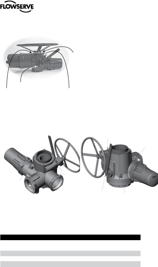
2 MX Actuator Subassembly
Figure 2.1 – Typical MX Actuator |
|
1 |
11 |
|
3
2
5
6
4 
14
|
|
|
7 |
Note: MX-05 with B4 base shown |
|
|
3 |
|
|
|
|
9 |
10 |
13 |
8 |
flowserve.com

Limitorque MX Maintenance and Spare Parts FCD LMENIM2314-00 – 07/08
2.1 MX Actuator Subassembly Components
Table 2.1 – MX Actuator Subassembly Components
No. Description
1Top-mounted handwheel
2Drive sleeve
3Worm shaft
4Motor
5Declutch lever
6Encoder
7Control panel (CP)
8Control module
9Optional bases Thrust base type
•A1 = Standard thrust base
•A1E = Extended-reach thrust base
10Baseplate-type B4 with stem nut options type:
•B4 = stem nut with variable bore and key
•B4E = extended-reach stem nut with variable bore and key
•BL = splined stem nut (SAE or Involute)
11 |
Handwheel adapter/handwheel worm gear |
|
|
12 |
Side-mounted handwheel (not shown, but available for the MX-10, -20,-85, -140, and -150) |
|
|
13 |
Encoder drive cartridge |
|
|
14 |
Terminal block |
2.1.1 Product Description
Your MX actuator controls the opening and closing travel of valves and other actuated devices. OPEN and CLOSED limits are protected by an absolute encoder that provides optical sensing of valve position and measures valve position in both motor and handwheel operation. No battery or backup power supply is required. Output torque is derived from motor speed, temperature, and voltage. If the preset torque is exceeded, the motor shuts off. As a result of this reliable and advanced protection technology, all valve and other actuated devices are protected from potential damage from overload, improper seating, and foreign obstructions.
A range of control and network options is available and can be easily added to the control capabilities already available on a standard actuator. Contact your local Limitorque distributor or Limitorque sales office for further information.
2.1.2 Storage
Storage Recommendations
Your MX actuator is double-sealed and weatherproof as shipped, providing all compartment covers and cable entry plugs are left intact. Actuators should be stored in a clean, dry, protected warehouse until
4 ready for installation. If actuators must be stored outdoors, they should be stored off the ground, high enough to prevent being immersed in water or buried in snow.
Limitorque MX Maintenance and Spare Parts FCD LMENIM2314-00 – 07/08
If your unit incorporates a rising stem application, it may be shipped with a plastic cap over the drive sleeve. If so, install a pipe plug or protective stem cover to protect the drive sleeve from possible corrosion.
Preferred Storage Orientation
Your MX actuator should be stored with the motor and terminal compartment in the horizontal position to obtain optimum service life.
2.1.3 Unit Weights
Table 2.2 – Unit weights
Unit |
lb. |
kg |
MX-05 |
|
24 |
52 |
||
|
|
|
MX-10 |
65 |
29 |
|
|
|
MX-20 |
109 |
49 |
|
|
|
MX-40 |
133 |
60 |
|
|
|
MX-85 |
259 |
117 |
|
|
|
MX-140 |
300 |
136 |
|
|
|
MX-150 |
410 |
186 |
|
|
|
NOTE: Weights include stem nut and lubricant.
2.2 Product Identification
2.2.1 Initial Inspection and Recording Suggestions
Upon receipt of the actuator, several steps should be initially followed to ensure condition of equipment and to establish proper record keeping.
1.After removing the actuator from the shipping carton or skid, thoroughly examine it for any physical damage which may have occurred during shipment. If you note any damage, immediately report the damage to the transport company and call Limitorque for further assistance.
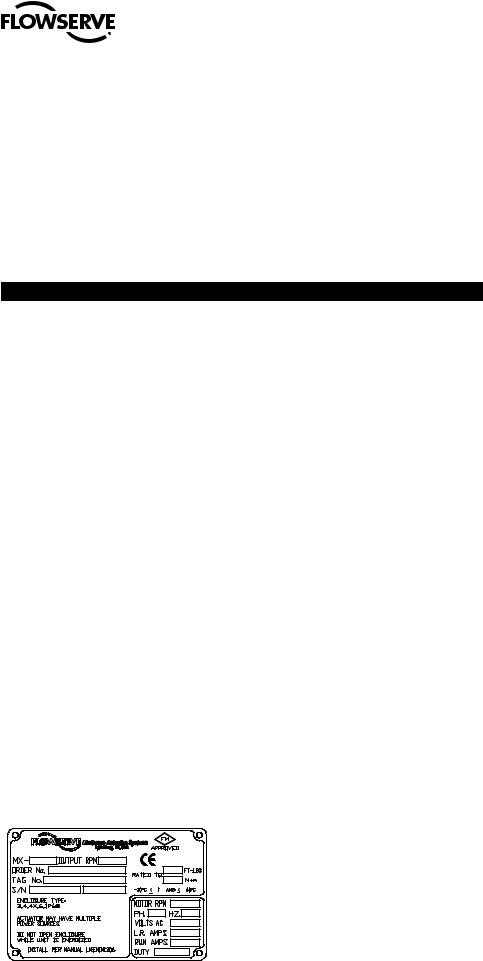
2.A nameplate with important information is attached to each actuator. Record the following information for use when you need to contact Limitorque with any questions about your actuator:
•Unit type/size
•Flowserve Limitorque order number
•Serial number
Figure 2.2 – MX Nameplate
5
flowserve.com

Limitorque MX Maintenance and Spare Parts FCD LMENIM2314-00 – 07/08
2.3 Maintenance
2.3.1 Recommended Maintenance
Under normal operating conditions, the MX is a maintenance-free actuator. Therefore, for normal applications, no formal actuator maintenance is required although visual inspection for oil leakage and excessive noise is recommended every 1 million drive sleeve turns or every 3000 cycles. When conditions are severe due to frequent operation or high temperatures, inspect the oil level and oil quality more often. Replace any seals that permit oil leakage or water ingress. When installing pipe plugs, use PTFE tape or paste to achieve a proper seal.
2.3.2 Unit Lubrication
Check for proper oil level every 1 million drive sleeve turns (reference Installation and Operation Manual - Diagnostics Section to learn how to view drive sleeve turns data). Change oil every 6000 unit cycles or if water or other foreign material is found during oil inspection.
Oil Level Inspection and Fill Criteria
(Reference Table 2.3 for oil capacities when mounted in varying positions)
• Actuator viewed in upright position (top-mounted handwheel up)
Oil level should be approximately 1 inch (25.4 mm) below the outer surface of the housing at the oil fill port.
NOTE: Do not overfill with oil because oil will expand during actuator operation. Actuators are shipped with an oil volume suitable for any mounting position. When checking the factory-supplied oil level, excess oil may drain from the highest oil fill port due to the various mounting orientations of each application.
•Actuator viewed in side-mounted position (terminal compartment up). Oil level should be up to the bottom of the oil fill plug.
•Actuator viewed in all other positions than described previously should have the oil capacities maintained. Fill through the highest oil fill port until the oil is at a level that will contact the bottom of the pipe plug when installed in oil fill port.
6
Limitorque MX Maintenance and Spare Parts FCD LMENIM2314-00 – 07/08
Figure 2.3 – Oil Fill/Plug Locations (MX-05 through -40)
t .9 TJEF NPVOUFE
IBOEXIFFM PJM DIFDL PJM mMM
t 0JM ESBJO BMM VOJUT
t .9 UPQ NPVOUFE t .9 UPQ NPVOUFE
IBOEXIFFM PJM DIFDL PJM mMM IBOEXIFFM PJM DIFDL PJM mMM t .9 TJEF NPVOUFE
IBOEXIFFM PJM DIFDL PJM mMM
Figure 2.4 – Oil Fill and Drain Locations (MX-85, -140, and -150)
0JM 1MVH
0JM 1MVH
0JM 1MVH
0JM 1MVH
0JM 1MVH
0JM 1MVH
Lubrication Data
•Oil Specifications: MX actuators are oil-filled using Mobil SHC-632, which is a synthetic oil suitable for ambient temperatures of -22°F to 250°F (-30°C to 120°C). For extreme low temperature conditions, alternative lubricants are available - consult factory for further information.
Table 2.3 – MX-05 and -10 Oil Capacities when using Oil Fill/Plug Ports
Nominal Oil Capacities |
oz. |
liters |
|
|
|
|
|
MX-05 |
|
|
|
|
10 |
0.3 |
|
|
|
|
|
MX-10 |
|
|
|
|
|
|
|
|
16 |
.05 |
|
|
|
|
7 |
MX-20 |
|
|
|
|
|
|
|
Top-mounted handwheel with handwheel up |
38 |
1.1 |
|
|
|
|
|
Top-mounted handwheel with terminal compartment up |
47 |
1.4 |
|
|
|
|
|
Side-mounted handwheel with terminal compartment up |
43 |
1.3 |
|
|
|
|
|
flowserve.com

Limitorque MX Maintenance and Spare Parts FCD LMENIM2314-00 – 07/08
MX-40
Top and side-mounted handwheel with handwheel up |
40 |
1.2 |
|
|
|
Top-mounted handwheel with terminal compartment up |
53 |
1.6 |
|
|
|
Side-mounted handwheel with terminal compartment up |
53 |
1.6 |
|
|
|
MX-85, -140, and -150 |
|
|
|
|
|
All Configurations |
192 |
5.7 |
|
|
|
2.3.3 O-Ring and Lubrication
O-rings and seals should be replaced any time an actuator is disassembled. Lubricate with a substance that is compatible with Buna N seals.
2.4 Subassembly Removal
and Remounting Procedures
This manual divides each MX actuator subassembly into a Removal and Remounting procedure. Use the following procedures to remove subassemblies for inspection, repair or replacement. Some subassemblies require prior subassembly removal before allowing the desired subassembly removal. Note the First Remove instructions at the beginning of each subassembly removal procedure. Remove these subassemblies first, and then remove the desired subassembly according to the instructions. Once removed, evaluate subassembly components to determine requirement for a new subassembly. If a new subassembly is required, see Section 2.5. Once components have been identified and replaced, remount following the appropriate Remounting procedures.
2.5 How to Order Replacement Subassemblies
2.5.1 Replacement Parts
Replacement parts are sold in modular subassemblies; therefore, when part replacement is required, order parts at the subassembly levels as shown in this manual. Parts may be ordered from your local Limitorque representative (see www.flowserve.com) or direct from the factory:
Telephone: 1-434-528-4400
Fax: 1-434-845-9736
8

Limitorque MX Maintenance and Spare Parts FCD LMENIM2314-00 – 07/08
Please have the following information, found on the actuator nameplate, available to help us facilitate your order:
•Unit type/size
•Limitorque order number
•Serial number
2.5.2 Return Procedure
When parts are identified for warranty or other component replacement, a Return Material Authorization (RMA) must be obtained from Flowserve. Contact factory for a RMA number (see contact information in section 2.5.1). All returned parts must be accompanied by documentation with the following information to obtain credit for returned goods:
•Return Material Authorization (RMA)
•Unit type/size
•Flowserve Limitorque order number
•Serial number
Return parts to the address listed below:
Limitorque Actuation Systems
5114 Woodall Road
Lynchburg, VA 24502
9
flowserve.com

Limitorque MX Maintenance and Spare Parts FCD LMENIM2314-00 – 07/08
This page is intentionally blank.
10

Limitorque MX Maintenance and Spare Parts FCD LMENIM2314-00 – 07/08
3 Remove Actuator
from Mounting Adapter
3.1 Actuator Removal with Type B1/B4/B4E Base (Torque)
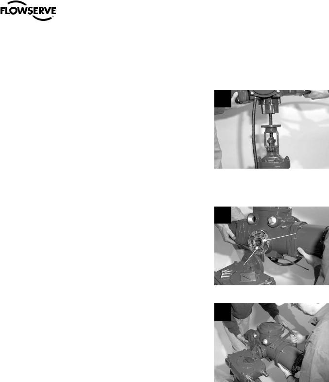
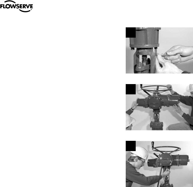
3.1.1 Removal (Type B1/B4/B4E Base)
STEP 1
cWARNING: Hazardous Voltage! Turn off all power sources to actuator before removing actuator from mounting plate. Power sources may include main power or control power. If necessary, disconnect incoming power leads L1, L2, L3, and control wiring from the terminal block.
Remove the bolts that secure the actuator
to the mounting adapter. If type B1 or B4E 1 base is used in addition to the standard type
B4 or B4E baseplate, you may leave the B1 base attached to the mounting adapter and remove the actuator only. Or if required, you may remove the bolts that mount type B1 base to mounting adapter. This will allow actuator removal along with optional B1 base.
11
flowserve.com
Limitorque MX Maintenance and Spare Parts FCD LMENIM2314-00 – 07/08
STEP 2
cWARNING: Potential high-pressure vessel! Before disassembling your actuator, ensure that the valve or other actuated device is isolated and is not under pressure.
Lift actuator from mounting adapter.
2
3.1.2 Remounting (Type B1/B4/B4E Base)
STEP 3
Ensure stem nut (#1-22) is secured inside actuator drive sleeve with retaining ring (#1-23). Lower the actuator onto the mating component, making sure to align stem nut key and keyway with mating component.
STEP 4
Ensure that the actuator and mounting adapter flange mating holes are aligned correctly.
3
1-22
1-23
4
12
Limitorque MX Maintenance and Spare Parts FCD LMENIM2314-00 – 07/08
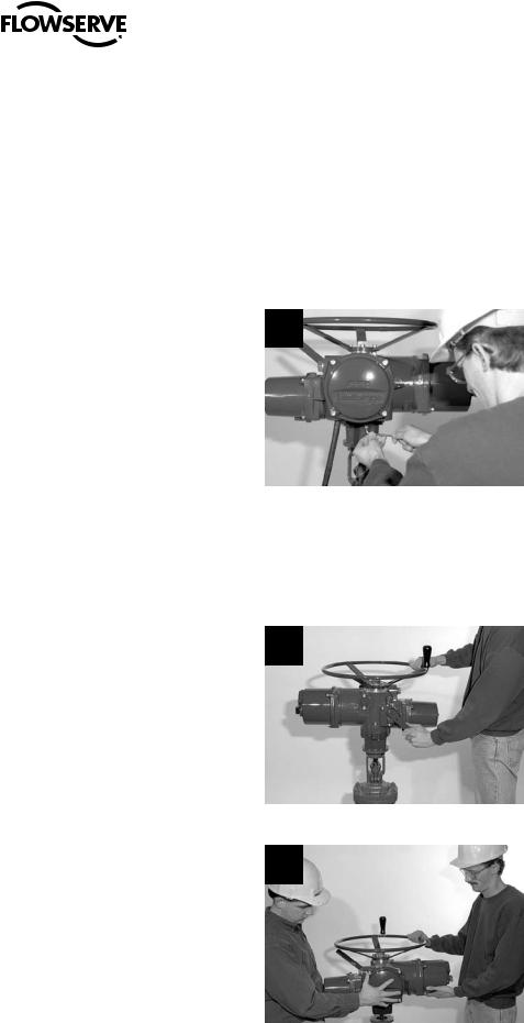
STEP 5
cWARNING: Hazardous Voltage! Turn off all power sources before rewiring incoming power leads L1, L2, L3, and control wiring in the terminal block.
Secure the actuator to the mounting adapter |
5 |
with mounting bolts. |
STEP 6
Reconnect incoming power leads L1, L2, L3, and control wiring to the terminal block. Restore power source when ready for operation.
13
flowserve.com
Limitorque MX Maintenance and Spare Parts FCD LMENIM2314-00 – 07/08
3.2 Actuator Removal with Type A1/A1E Base (Thrust)
NOTE: Two procedure options are available for removing the actuator and thrust base:
1.Remove actuator from thrust base, leaving thrust base mounted to mounting flange or removing thrust base separately.
2.Remove actuator and thrust base as a unit from mounting flange.
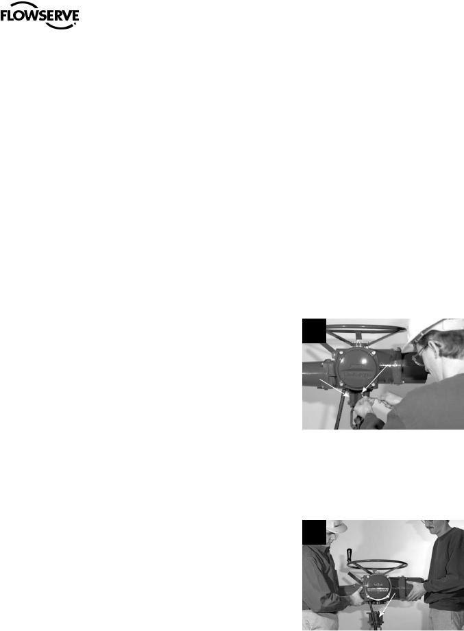
3.2.1 Removal (Type A1/A1E Base)
Actuator Removal Separate from Thrust Base
STEP 1
cWARNING: Hazardous Voltage! Turn off all power sources to actuator before removing actuator from mounting plate. Power sources may include main power or control power. If necessary, disconnect incoming power leads L1, L2, L3, and control wiring from the terminal block.
Remove the bolts (#10-10) that secure the |
1 |
actuator to the thrust base assembly (#10). |
10-10
10
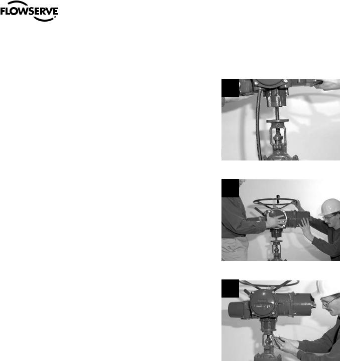
STEP 2
cWARNING: Potential high-pressure vessel! Before disassembling your actuator, ensure that the valve or other actuated device is isolated and is not under pressure.
Lift actuator from thrust base assembly (#10).
2
10
14

Limitorque MX Maintenance and Spare Parts FCD LMENIM2314-00 – 07/08
STEP 3
cWARNING: Potential for actuated device to change position! The thrust base will maintain position only if non-backdriving thread lead is used. Ensure proper thread lead is used in your application before allowing thrust base to be used for maintaining position when actuator is removed.
Thrust base removal (if required)
The valve position will be maintained if a 3 locking thread lead is used on the valve stem.
If thrust base removal is required, use the following removal procedure.
Remove the bolts that secure the thrust base to the mounting adapter.
STEP 4
Rotate the thrust base (#10) until it feeds off the threaded stem.
4
10
3.2.2 Remounting (Type A1/A1E Base)
Actuator Remounting Separate from Thrust Base
STEP 5
5
Thrust base remounting (if required)
Ensure the thrust base stem nut has the two lugs positioned upward to engage with the drive sleeve slots when actuator is reinstalled onto thrust base. Thread thrust base back onto mounting adapter.
15
flowserve.com
Limitorque MX Maintenance and Spare Parts FCD LMENIM2314-00 – 07/08
STEP 6
Secure thrust base to mounting adapter with mounting bolts.
6
STEP 7
Actuator remounting
Lower the actuator onto the thrust base, making sure thrust nut lugs align and properly engage with drive sleeve slots.
STEP 8
Install bolts (#10-10) to secure the actuator to the thrust base assembly (#10).
7
8
STEP 9
cWARNING: Hazardous Voltage! Turn off all power sources before rewiring incoming power leads L1, L2, L3, and control wiring in the terminal block.
Reconnect incoming power leads L1, L2, L3, and control wiring to the terminal block. Restore power source when ready for operation.
16
Limitorque MX Maintenance and Spare Parts FCD LMENIM2314-00 – 07/08
3.2.3 Removal (Type A1/A1E Base)
Actuator and Thrust Base as a Unit
STEP 1
cWARNING: Hazardous Voltage! Turn off all power sources to actuator before removing actuator from mounting plate. Power sources may include main power or control power. If necessary, disconnect incoming power leads L1, L2, L3, and control wiring from the terminal block.
Actuator and thrust base removal
Remove the bolts that secure the actuator and 1 thrust base (#10) to the mounting adapter.
STEP 2
cWARNING: Potential high-pressure vessel! Before disassembling your actuator, ensure that the valve or other actuated device is isolated and is not under pressure.
Declutch the actuator to manual mode.
2
STEP 3
Rotate the handwheel until the actuator lifts off the threaded stem.
3
17
flowserve.com
Limitorque MX Maintenance and Spare Parts FCD LMENIM2314-00 – 07/08
3.2.4 Remounting (Type A1/A1E Base)
Actuator and Thrust Base as a Unit
STEP 4
Actuator and thrust base remounting
4
Declutch the actuator to manual mode. Lift actuator up to the threaded stem and carefully align threads with thrust base threaded stem nut.
STEP 5
Rotate the handwheel to lower the actuator along the threaded stem and onto the mounting adapter plate.
STEP 6
Install the mounting bolts to secure the actuator and thrust base (#10) to the mounting adapter.
5
6
STEP 7
cWARNING: Hazardous Voltage! Turn off all power sources before rewiring incoming power leads L1, L2, L3, and control wiring in the terminal block.
Reconnect incoming power leads L1, L2, L3, and control wiring to the terminal block. Restore power source when ready for operation.
18
Limitorque MX Maintenance and Spare Parts FCD LMENIM2314-00 – 07/08
4 Mechanical Assemblies
4.1 Motor
NOTE: Proper motor testing is required when replacing motor. Consult your Limitorque representative or the Limitorque factory to replace with correct motor.
Table 4.1 – Motor Parts List
Part Number |
Description |
Qty. |
|
4-1 |
Motor cover |
1 |
|
4-2 |
Stator |
1 |
|
4-3 |
Rotor assembly |
1 |
|
4-4 |
Bearing |
1 |
|
4-8 |
Bearing preload spring |
1 |
|
4-9 |
Setscrew |
1 |
|
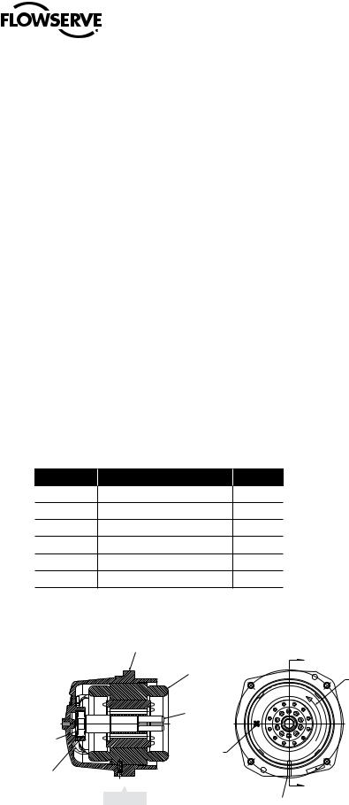
Figure 4.1 – Motor (MX-05, -10, -20, and -40) |
|
|
|
|
4-1 |
|
|
|
4-2 |
|
A |
|
|
Assembly must have |
|
|
|
|
|
|
|
|
rotation of rotor as shown. |
|
4-3 |
|
Phase connections are: |
|
|
|
T1-Phase 'A' |
4-8 |
|
|
T2-Phase 'B' |
Motor |
|
T3-Phase 'C' |
|
|
|
|
|
|
leads |
|
|
4-4 |
|
|
A |
|
View A-A |
|
|
|
4-9 |
19 |
|
flowserve.com
Limitorque MX Maintenance and Spare Parts FCD LMENIM2314-00 – 07/08
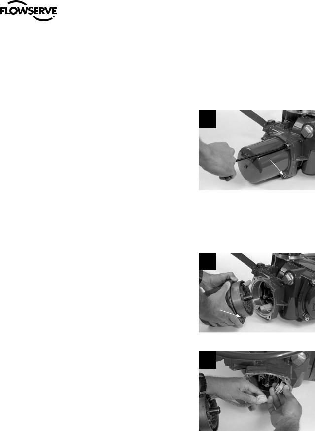
4.1.1 Removal
STEP 1
cWARNING: Hazardous Voltage! Turn off all power sources to actuator before removing motor assembly. Power sources may include main power or control power.
Using an M6 hex key, remove the four M8
screws (#1-14) that mount the motor assembly 1 to the MX-05 through MX-40 actuator.
MX-85 requires an M8 hex key and uses an
M10 screw.
1-14
STEP 2
aCAUTION: The rotor is not connected to the motor housing; when removing the motor, ensure the rotor is carefully removed and not dropped from the motor housing.
Withdraw the complete motor (subassembly #4), including the rotor (#4-3), until the wiring harness is accessible. Note the O-ring (#1-15) on the spigot/pilot of the motor assembly; replace at remounting.
STEP 3
Disconnect the motor power plug from the motor power socket connector.
2
 4-3
4-3
1-15
3
20
Limitorque MX Maintenance and Spare Parts FCD LMENIM2314-00 – 07/08
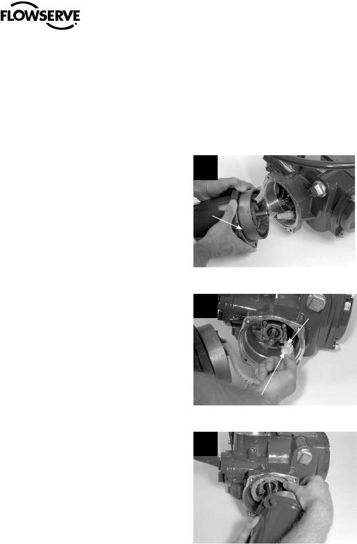
4.1.2 Remounting
STEP 4
cWARNING: Hazardous Voltage! Turn off all power sources to actuator before removing motor assembly. Power sources may include main power or control power.
Lightly lubricate the O-ring (#1-15) that is installed around the motor spigot/pilot (subassembly #4).
STEP 5
Hold the motor assembly (housing/stator/rotor) close to the actuator housing and reconnect the motor power plug to the motor power socket connector.
4
1-15
5 Motor Power
Socket
Connector
Motor Power
Plug
STEP 6
Coil the spiral-wrapped motor power wiring inside the motor cavity and around the motor bearing housing to ensure that it does not come into contact with the rotor shaft.
6
MX-05 through -40 motor wiring will wrap around about 360°. MX-85/140/150 motor wiring will wrap around about 180°.
21
flowserve.com

Limitorque MX Maintenance and Spare Parts FCD LMENIM2314-00 – 07/08
STEP 7
Push the rotor shaft onto the protruding worm shaft, aligning the rotor shaft slots with the worm shaft pin. Slide the motor housing spigot/pilot into the actuator housing.
7
STEP 8
Fit the four screws (#1-14) into the motor subassembly mounting holes and tighten.
8
1-14
4.1.3Removal and mounting of MX-140 motor (40 RPM and greater)
Table 4.2 – Motor Parts List
Part Number |
|
Description |
Qty. |
1-14 |
|
Socket head cap screw |
|
|
4 |
||
|
|
|
|
1-15 |
|
O-ring |
1 |
|
|
|
|
4-7 |
|
Motor |
1 |
|
|
|
|
4-8 |
|
Adapter, motor |
1 |
|
|
|
|
4-9 |
|
Socket head cap screw |
4 |
|
|
|
|
4-10 |
|
O-ring |
1 |
|
|
|
|
Figure 4.2 – Motor and Adapter (MX-140)
MAIN UNIT ASSEMBLY
4-8 1-14
4-10
1-15
22
4-7
4-9
 Loading...