


USER INSTRUCTIONS
M Slurry Pump |
Installation |
|
Operation |
Standard and Severe Duty (includes MX & MS options) |
Maintenance |
|
|
PCN=71569241 – 02/08 (E) |
|

M SLURRY USER INSTRUCTION ENGLISH 71569241 - 02/08
 ®
®
CONTENTS |
|
|
|
|
PAGE |
1 INTRODUCTION AND SAFETY ........................... |
4 |
|
1.1 |
General ........................................................... |
4 |
1.2 |
CE marking and approvals.............................. |
4 |
1.3 |
Disclaimer ....................................................... |
4 |
1.4 |
Copyright......................................................... |
4 |
1.5 |
Duty conditions................................................ |
4 |
1.6 |
Safety .............................................................. |
5 |
1.7 |
Nameplate and warning labels........................ |
8 |
1.8 |
Specific machine performance...................... |
10 |
1.9 |
Noise level..................................................... |
10 |
2 TRANSPORT AND STORAGE ........................... |
11 |
|
2.1 |
Consignment receipt and unpacking............. |
11 |
2.2 |
Handling ........................................................ |
11 |
2.3 |
Lifting............................................................. |
11 |
2.4 |
Storage .......................................................... |
11 |
2.5 |
Recycling and end of product life.................. |
12 |
3 PUMP DESCRIPTION......................................... |
12 |
|
3.1 |
Configurations............................................... |
12 |
3.2 |
Name nomenclature...................................... |
12 |
3.3 |
Design of major parts .................................... |
12 |
3.4 |
Performance and operating limits ................. |
13 |
3.5 |
Engineering Data .......................................... |
14 |
4 INSTALLATION.................................................... |
21 |
|
4.1 |
Location......................................................... |
21 |
4.2 |
Part assemblies............................................. |
21 |
4.3 |
Foundation .................................................... |
21 |
4.4 |
Baseplate installation .................................... |
21 |
4.5 |
Initial alignment ............................................. |
22 |
4.6 |
Grouting ........................................................ |
24 |
4.7 |
Piping ............................................................ |
24 |
4.8 |
Final shaft alignment check .......................... |
26 |
4.9 |
Electrical connections ................................... |
26 |
4.10 Protection systems...................................... |
27 |
|
5 COMMISSIONING, START-UP, OPERATION AND |
||
SHUTDOWN .................................................... |
27 |
|
5.1 |
Lubrication Methods...................................... |
27 |
5.2 |
Pump lubricants ............................................ |
28 |
5.3 |
Direction of rotation....................................... |
29 |
5.4 |
Guarding ....................................................... |
29 |
5.5 |
Priming and auxiliary supplies ...................... |
29 |
5.6 |
Starting the pump.......................................... |
30 |
5.7 |
Running the pump......................................... |
30 |
5.8 |
Stopping and shutdown ................................ |
31 |
5.9 |
Hydraulic, mechanical and electrical duty..... |
31 |
6 MAINTENANCE................................................... |
32 |
|
6.1 |
General ......................................................... |
32 |
6.2 |
Maintenance schedule .................................. |
32 |
6.3 |
Spare parts.................................................... |
35 |
6.4 |
Recommended spares and consumable items35 |
|
6.5 |
Tools required ............................................... |
35 |
6.6 |
Fastener torques........................................... |
36 |
6.7 |
|
Renewal clearances ...................................... |
36 |
6.8 |
|
Disassembly .................................................. |
36 |
6.9 |
|
Examination of parts..................................... |
38 |
6.10 |
Assembly ..................................................... |
39 |
|
6.11 |
Impeller axial clearance adjustment ............ |
45 |
|
7 FAULTS; CAUSES AND REMEDIES................... |
47 |
||
8 PARTS LIST AND DRAWINGS............................ |
50 |
||
8.1 |
Standard Duties-Frames 1 & 2 ....................... |
50 |
|
8.2 |
Standard Duty-Frames 1&2 with Expeller ...... |
51 |
|
8.3 |
Standard Duty Frame 3 & 4............................ |
52 |
|
8.4 |
|
Standard Duty - Frame 3&4 with Expeller ..... |
53 |
8.5 |
Severe Duty-Frames 2,3 & 4 .......................... |
54 |
|
8.6 |
Severe Duty-Frames 3&4 with Expeller ......... |
55 |
|
8.7 |
Severe Duty-Frames 5&6 ............................... |
56 |
|
8.8 |
Severe Duty –Frame 5&6 with Expeller ......... |
57 |
|
8.9 |
|
General arrangement drawing....................... |
58 |
9 CERTIFICATION.................................................. |
58 |
||
10 OTHER RELEVANT DOCUMENTATION AND |
|
||
MANUALS ........................................................ |
58 |
||
10.1 |
Supplementary User Instruction manuals ... |
58 |
|
10.2 |
Change notes .............................................. |
58 |
|
10.3 |
Additional sources of information ................ |
58 |
|
Page 2 of 60

M SLURRY USER INSTRUCTION ENGLISH 71569241 - 02/08
 ®
®
INDEX
PAGE |
|
Alignment of shafting (see 4.5, 4.7 and 4.3)............ |
22 |
CE marking and approvals (1.2)................................ |
3 |
Clearances (see 6.7, Renewal clearances)............. |
34 |
Clearance setting (6.11) .......................................... |
43 |
Commissioning and operation (see 5)..................... |
27 |
Configurations (3.1) ................................................. |
12 |
Direction of rotation (5.3) ......................................... |
29 |
Dismantling (see 6.8, Disassembly) ........................ |
35 |
Duty conditions (1.5).................................................. |
3 |
Electrical connections (4.8) ..................................... |
15 |
Examination of parts (6.9)........................................ |
25 |
Faults; causes and remedies................................... |
45 |
General assembly drawings (see 8) ........................ |
48 |
Grouting (4.4)........................................................... |
21 |
Guarding (5.4).......................................................... |
29 |
Handling (2.2) ............................................................ |
9 |
Hydraulic, mechanical and electrical duty (5.9)....... |
31 |
Lifting (2.3)............................................................... |
11 |
Location (4.1)........................................................... |
21 |
Lubrication schedule (see 5.2, Pump lubricants) .... |
28 |
Maintenance schedule (6.2) .................................... |
32 |
Piping (4.7) .............................................................. |
24 |
Priming and auxiliary supplies (5.5)......................... |
29 |
Reassembly (see 6.10, Assembly) .......................... |
36 |
Replacement parts (see 6.3 and 6.4) ...................... |
34 |
Safety, electrical (see 4.9) ....................................... |
26 |
Safety, protection systems (see 1.6) ......................... |
5 |
Sound level (see 1.9, Noise level) ............................. |
8 |
Specific machine performance (1.8).......................... |
8 |
Starting the pump (5.6)............................................ |
29 |
Stopping and shutdown (5.8)................................... |
31 |
Storage (2.4).............................................................. |
9 |
Supplementary manuals or information sources ..... |
56 |
Tools required (6.5) ................................................. |
34 |
Torques for fasteners (6.6) ...................................... |
34 |
Page 3 of 60

M SLURRY USER INSTRUCTION ENGLISH 71569241 - 02/08
 ®
®
1 INTRODUCTION AND SAFETY
1.1 General
 These instructions must always be kept close to the product's operating location or directly with the product.
Flowserve's products are designed, developed and manufactured with state-of-the-art technologies in modern facilities. The unit is produced with great care and commitment to continuous quality control, utilising sophisticated quality techniques, and safety requirements.
We are committed to continuous quality improvement and being at your service for any further information about the product in its installation and operation or about its support products, repair and diagnostic services.
These instructions are intended to facilitate familiarization with the product and its permitted use. Operating the product in compliance with these instructions is important to help ensure reliability in service and avoid risks. The instructions may not take into account local regulations; ensure such regulations are observed by all, including those installing the product. Always coordinate repair activity with operations personnel, and follow all plant safety requirements and applicable safety and health laws and regulations.
 These instructions must be read prior to installing, operating, using and maintaining the equipment in any region worldwide. The equipment must not be put into service until all the conditions relating to safety noted in the instructions, have been met.
1.2 CE marking and approvals
It is a legal requirement that machinery and equipment put into service within certain regions of the world shall conform with the applicable CE Marking Directives covering Machinery and, where applicable, Low Voltage Equipment, Electromagnetic Compatibility (EMC), Pressure Equipment Directive (PED) and Equipment for Potentially Explosive Atmospheres (ATEX).
Where applicable, the Directives and any additional Approvals, cover important safety aspects relating to machinery and equipment and the satisfactory provision of technical documents and safety instructions. Where applicable this document incorporates information relevant to these Directives.
To establish approvals and if the product itself is CE marked, check the serial number plate and the Certification. (See section 9, Certification.)
1.3 Disclaimer
Information in these User Instructions is believed to be reliable. In spite of all the efforts of Flowserve Corporation to provide sound and all necessary information the content of this manual may appear insufficient and is not guaranteed by Flowserve as to its completeness or accuracy.
Flowserve manufactures products to exacting International Quality Management System Standards as certified and audited by external Quality Assurance organisations. Genuine parts and accessories have been designed, tested and incorporated into the products to help ensure their continued product quality and performance in use. As Flowserve cannot test parts and accessories sourced from other vendors the incorrect incorporation of such parts and accessories may adversely affect the performance and safety features of the products. The failure to properly select, install or use authorised Flowserve parts and accessories is considered to be misuse. Damage or failure caused by misuse is not covered by Flowserve's warranty. In addition, any modification of Flowserve products or removal of original components may impair the safety of these products in their use.
1.4 Copyright
All rights reserved. No part of these instructions may be reproduced, stored in a retrieval system or transmitted in any form or by any means without prior permission of Flowserve Pump Division.
1.5 Duty conditions
This product has been selected to meet the specifications of your purchaser order. The acknowledgement of these conditions has been sent separately to the Purchaser. A copy should be kept with these instructions.
 The product must not be operated beyond the parameters specified for the application. If there is any doubt as to the suitability of the product for the application intended, contact Flowserve for advice, quoting the serial number.
If the conditions of service on your purchase order are going to be changed (for example liquid pumped, temperature or duty) it is requested that you/the user seek our written agreement before start up.
Page 4 of 60

M SLURRY USER INSTRUCTION ENGLISH 71569241 - 02/08
 ®
®
1.6 Safety
1.6.1 Summary of safety markings
These user instructions contain specific safety markings where non-observance of an instruction would cause hazards. The specific safety markings are:
 This symbol indicates electrical safety instructions where non-compliance would affect personal safety.
 This symbol indicates safety instructions where non-compliance would affect personal safety.
 This symbol indicates safety instructions where non-compliance would affect protection of a safe life environment.
 This symbol indicates safety instructions where non-compliance would affect the safe operation or protection of the pump or pump unit.
 This symbol indicates explosive atmosphere zone marking according to ATEX. It is used in safety instructions where non-compliance in the hazardous area would cause the risk of an explosion.
 This sign is not a safety symbol but indicates an important instruction in the assembly process.
1.6.2 Personnel qualification and training
All personnel involved in the operation, installation, inspection and maintenance of the unit must be qualified to carry out the work involved. If the personnel in question do not already possess the necessary knowledge and skill, appropriate training and instruction must be provided. If required the operator may commission the manufacturer/supplier to provide applicable training.
Always coordinate repair activity with operations and health and safety personnel, and follow all plant safety requirements and applicable safety and health laws and regulations.
1.6.3 Safety action
This is a summary of conditions and actions to prevent injury to personnel and damage to the environment and to equipment. (For products used in potentially explosive atmospheres section 1.6.4 also applies.)
 PREVENT EXCESSIVE EXTERNAL PIPE LOAD
Do not use pump as a support for piping. Do not mount expansion joints, unless allowed by Flowserve in writing, so that their force, due to internal pressure, acts on the pump flange.
 ENSURE CORRECT LUBRICATION (See section 5, Commissioning, startup, operation and shutdown.)
 START THE PUMP WITH OUTLET VALVE PART OPENED
(Unless otherwise instructed at a specific point in the user instructions.)
This is recommended to minimize the risk of overloading and damaging the pump motor at full or zero flow. Pumps may be started with the valve further open only on installations where this situation cannot occur. The pump outlet control valve may need to be adjusted to comply with the duty following the run-up process. (See section 5, Commissioning start-up, operation and shutdown.)
 NEVER RUN THE PUMP DRY
 INLET VALVES TO BE FULLY OPEN WHEN PUMP IS RUNNING
Running the pump at zero flow or below the recommended minimum flow continuously will cause damage to the seal.
 DO NOT RUN THE PUMP AT ABNORMALLY HIGH OR LOW FLOW RATES Operating at a flow rate higher than normal or at a flow rate with no back pressure on the pump may overload the motor and cause cavitation. Low flow rates may cause a reduction in pump/bearing life, overheating of the pump, instability and cavitation/ vibration.
 NEVER DO MAINTENANCE WORK WHEN THE UNIT IS CONNECTED TO POWER


 HAZARDOUS LIQUIDS
When the pump is handling hazardous liquids care must be taken to avoid exposure to the liquid by appropriate siting of the pump, limiting personnel access and by operator training. If the liquid is flammable and/or explosive, strict safety procedures must be applied.
Gland packing must not be used when pumping hazardous liquids.
 DRAIN THE PUMP AND ISOLATE PIPEWORK BEFORE DISMANTLING THE PUMP
The appropriate safety precautions should be taken where the pumped liquids are hazardous.
Page 5 of 60
M SLURRY USER INSTRUCTION ENGLISH 71569241 - 02/08
 ®
®
 FLUORO-ELASTOMERS (When fitted.)
When a pump has experienced temperatures over 250 ºC (482 ºF), partial decomposition of fluoro-elastomers (eg Viton) will occur. In this condition these are extremely dangerous and skin contact must be avoided.
 HANDLING COMPONENTS
Many precision parts have sharp corners and the wearing of appropriate safety gloves and equipment is required when handling these components. To lift heavy pieces above 25 kg (55 lb) use a crane appropriate for the mass and in accordance with current local regulations.
 GUARDS MUST NOT BE REMOVED WHILE THE PUMP IS OPERATIONAL
 THERMAL SHOCK
Rapid changes in the temperature of the liquid within the pump can cause thermal shock, which can result in damage or breakage of components and should be avoided.
 NEVER APPLY HEAT TO REMOVE IMPELLER Trapped lubricant or vapour could cause an explosion.
 HOT (and cold) PARTS
If hot or freezing components or auxiliary heating supplies can present a danger to operators and persons entering the immediate area action must be taken to avoid accidental contact. If complete protection is not possible, the machine access must be limited to maintenance staff only, with clear visual warnings and indicators to those entering the immediate area. Note: bearing housings must not be insulated and drive motors and bearings may be hot.
If the temperature is greater than 68 °C (175 °F) or below 5 °C (20 °F) in a restricted zone, or exceeds local regulations, action as above shall be taken.
1.6.4 Products used in potentially explosive atmospheres
 Measures are required to:
•Avoid excess temperature
•Prevent build up of explosive mixtures
•Prevent the generation of sparks
•Prevent leakages
•Maintain the pump to avoid hazard
The following instructions for pumps and pump units when installed in potentially explosive atmospheres must be followed to help ensure explosion protection.
Both electrical and non-electrical equipment must meet the requirements of European Directive 94/9/EC.
1.6.4.1 Scope of compliance
 Use equipment only in the zone for which it is appropriate. Always check that the driver, drive coupling assembly, seal and pump equipment are suitably rated and/or certified for the classification of the specific atmosphere in which they are to be installed.
Where Flowserve has supplied only the bare shaft pump, the Ex rating applies only to the pump. The party responsible for assembling the pump set shall select the coupling, driver and any additional equipment, with the necessary CE Certificate/ Declaration of Conformity establishing it is suitable for the area in which it is to be installed.
The output from a variable frequency drive (VFD) can cause additional heating affects in the motor and so, for pumps sets with a VFD, the ATEX Certification for the motor must state that it is covers the situation where electrical supply is from the VFD. This particular requirement still applies even if the VFD is in a safe area.
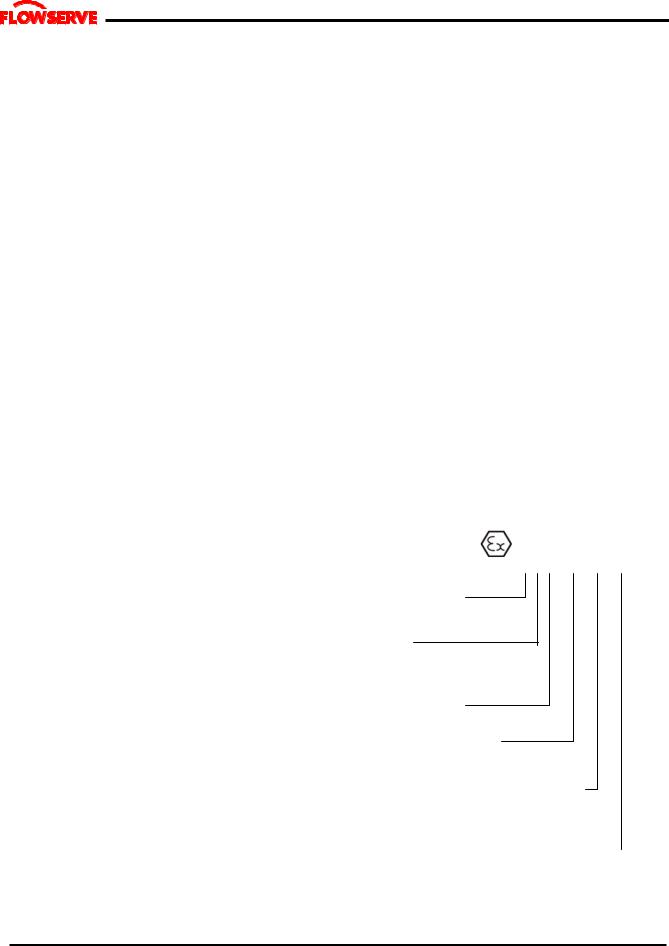
1.6.4.2 Marking
An example of ATEX equipment marking is shown below. The actual classification of the pump will be engraved on the nameplate.
II 2 GD c IIC 135 ºC (T4)
Equipment Group I = Mining
II = Non-mining
Category
2 or M2 = High level protection
3 = normal level of protection
Gas and/or Dust G = Gas; D= Dust
c = Constructional safety
(in accordance with En13463-5)
Gas Group (Equipment Category 2 only)
IIA – Propane (typical)
IIB – Ethylene (typical)
IIC – Hydrogen (typical)
Maximum surface temperature (Temperature Class) (See section 1.6.4.3.)
Page 6 of 60

M SLURRY USER INSTRUCTION ENGLISH 71569241 - 02/08
 ®
®
1.6.4.3 Avoiding excessive surface temperatures
 ENSURE THE EQUIPMENT TEMPERATURE CLASS IS SUITABLE FOR THE HAZARD ZONE
Pumps have a temperature class as stated in the ATEX Ex rating on the nameplate. These are based on a maximum ambient of 40 °C (104 °F); refer to Flowserve for higher ambient temperatures.
The surface temperature on the pump is influenced by the temperature of the liquid handled. The maximum permissible liquid temperature depends on the temperature class and must not exceed the values in the table that follows.
The temperature rise at the seals and bearings and due to the minimum permitted flow rate is taken into account in the temperatures stated.
Temperature |
Maximum |
Temperature limit of liquid |
|
surface |
handled (* depending on |
||
class to |
|||
temperature |
material and construction |
||
prEN 13463-1 |
|||
permitted |
variant - check which is lower) |
||
|
|||
T6 |
85 °C (185 °F) |
Consult Flowserve |
|
T5 |
100 °C (212 °F) |
Consult Flowserve |
|
T4 |
135 °C (275 °F) |
115 °C (239 °F) * |
|
T3 |
200 °C (392 °F) |
180 °C (356 °F) * |
|
T2 |
300 °C (572 °F) |
275 °C (527 °F) * |
|
T1 |
450 °C (842 °F) |
400 °C (752 °F) * |
The responsibility for compliance with the specified maximum liquid temperature is with the plant operator.
Temperature classification “Tx” is used when the liquid temperature varies and when the pump is required to be used in differently classified potentially explosive atmospheres. In this case the user is responsible for ensuring that the pump surface temperature does not exceed that permitted in its actual installed location.
If an explosive atmosphere exists during the installation, do not attempt to check the direction of rotation by starting the pump unfilled. Even a short run time may give a high temperature resulting from contact between rotating and stationary components.
Where there is any risk of the pump being run against a closed valve generating high liquid and casing external surface temperatures it is recommended that users fit an external surface temperature protection device.
Avoid mechanical, hydraulic or electrical overload by using motor overload trips, temperature monitor or a
power monitor and make routine vibration monitoring checks.
In dirty or dusty environments, regular checks must be made and dirt removed from areas around close clearances, bearing housings and motors.
1.6.4.4 Preventing the build up of explosive mixtures
 ENSURE THE PUMP IS PROPERLY FILLED AND VENTED AND DOES NOT RUN DRY
Ensure the pump and relevant suction and discharge pipeline system is totally filled with liquid at all times during the pump operation, so that an explosive atmosphere is prevented. In addition it is essential to make sure that seal chambers, auxiliary shaft seal systems and any heating and cooling systems are properly filled.
If the operation of the system cannot avoid this condition the fitting of an appropriate dry run protection device is recommended (eg liquid detection or a power monitor).
To avoid potential hazards from fugitive emissions of vapour or gas to atmosphere the surrounding area must be well ventilated.
1.6.4.5 Preventing sparks
 To prevent a potential hazard from mechanical contact, the coupling guard must be non-sparking and anti-static for Category 2.
To avoid the potential hazard from random induced current generating a spark, the earth contact on the baseplate must be used.
Avoid electrostatic charge: do not rub non-metallic surfaces with a dry cloth; ensure cloth is damp.
The coupling must be selected to comply with 94/9/EC and correct alignment must be maintained.
1.6.4.6 Preventing leakage
 The pump must only be used to handle liquids for which it has been approved to have the correct corrosion resistance.
Avoid entrapment of liquid in the pump and associated piping due to closing of suction and discharge valves, which could cause dangerous excessive pressures to
Page 7 of 60

M SLURRY USER INSTRUCTION ENGLISH 71569241 - 02/08
 ®
®
occur if there is heat input to the liquid. This can occur if the pump is stationary or running.
Bursting of liquid containing parts due to freezing must be avoided by draining or protecting the pump and ancillary systems.
Where there is the potential hazard of a loss of a seal barrier fluid or external flush, the fluid must be monitored.
If leakage of liquid to atmosphere can result in a hazard, the installation of a liquid detection device is recommended.
1.6.4.7 Maintenance to avoid the hazard
 CORRECT MAINTENANCE IS REQUIRED TO AVOID POTENTIAL HAZARDS WHICH GIVE A RISK OF EXPLOSION
The responsibility for compliance with maintenance instructions is with the plant operator.
1.7 Nameplate and warning labels
To avoid potential explosion hazards during maintenance, the tools, cleaning and painting materials used must not give rise to sparking or adversely affect the ambient conditions. Where there is a risk from such tools or materials, maintenance must be conducted in a safe area.
It is recommended that a maintenance plan and schedule is adopted. (See section 6, Maintenance.)
1.7.1 Nameplate
For details of nameplate, see the Declaration of Conformity.
1.7.2 Warning labels
WARNING
MECHANICAL SEAL FITTED
DO NOT ADJUST PUMP CLEARANCE WITHOUT REFERENCE TO MANUFACTURER’S INSTRUCTION MANUAL
MECHANICAL SEAL WARNING
P/N 2113931-001
WARNING
BEFORE STARTING THE PUMP ON SERVICE, CHECK TO ENSURE CORRECT ROTATION OF MOTOR. FAILURE TO DO THIS COULD RESULT IN SERIOUS DAMAGE TO THE EQUIPMENT.
ROTATION WARNING
P/N 2113932-001
WARNING
BEFORE GROUTING, REALIGN THIS UNIT RECHECK ALIGNMENT BEFORE STARING, FAILURE TO DO THIS COULD RESULT IN SERIOUS DAMAGE TO THE EQUIPMENT.
REFER TO INSTALLATION MANUAL AND, OR COUPLING INSTRUCTIONS FOR METHOD OF CHECKING ALIGNMENT.
GROUT WARNING
P/N 2113934-001
WARNING
THESE EYEBOLTS
ARE TO BE USED FOR LIFTING BEARING CARTRIDGE AND SHAFT ONLY.
DO NOT USE FOR LIFTING ENTIRE UNIT.
LIFTING WARNING
P/N 9901701-001
Page 8 of 60
M SLURRY USER INSTRUCTION ENGLISH 71569241 - 02/08
 ®
®
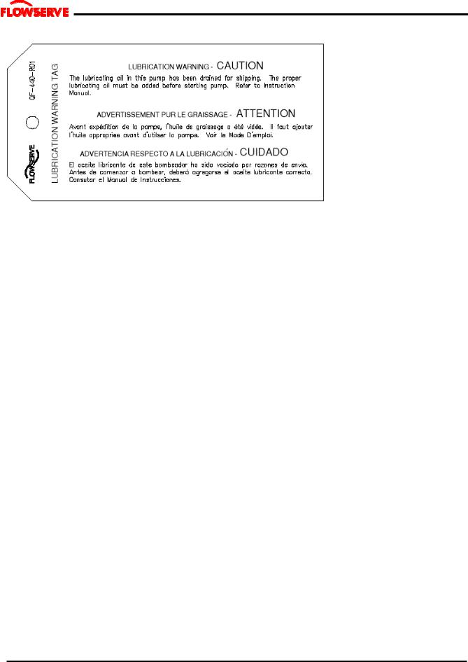
LUBRICATION WARNING – QF-440-R01 (2124841)
Oil lubricated units only:
Page 9 of 60

M SLURRY USER INSTRUCTION ENGLISH 71569241 - 02/08
 ®
®
1.8 Specific machine performance
For performance parameters see section 1.5, Duty conditions. When the contract requirement specifies these to be incorporated into User Instructions these are included here. Where performance data has been supplied separately to the purchaser these should be obtained and retained with these User Instructions if required.
1.9 Noise level
When pump noise level exceeds 85 dBA attention must be given to prevailing Health and Safety Legislation, to limit the exposure of plant operating personnel to the noise. The usual approach is to control exposure time to the noise or to enclose the machine to reduce emitted sound. You may have already specified a limiting noise level when the equipment was ordered, however if no noise requirements were defined then machines above a certain power level will exceed 85 dBA. In such situations consideration must be given to the fitting of an acoustic enclosure to meet local regulations.
Pump noise level is dependent on a number of factors - the type of motor fitted, the operating capacity, pipework design and acoustic characteristics of the building. The levels specified in the table below are estimated and not guaranteed.
The dBA values are based on the noisiest ungeared electric motors that are likely to be encountered. They are Sound Pressure levels at 1 m (3.3 ft) from the directly driven pump, for "free field over a reflecting plane". For estimating LwA sound power level (re 1 pW) add 14dBA to the sound pressure value.
If a pump unit only has been purchased, for fitting with your own driver, then the "pump only" noise levels from the table should be combined with the level for the driver obtained from the supplier. If the motor is driven by an inverter, it may show an increase in noise level at some speeds. Consult a Noise Specialist for the combined calculation.
For units driven by equipment other than
electric motors or units contained within enclosures, see the accompanying information sheets and manuals.
M SLURRY |
Noise Level dbA |
Pump speed |
Sound Power |
pump size |
(at 1 m (3 ft) reference 20 µPa) |
rpm |
Level dbA |
2 M091 |
75 |
2250 |
89 |
3 M091 |
75 |
2250 |
89 |
3 M111 |
77 |
2000 |
91 |
4 M122 |
80 |
1780 |
94 |
5 M142 |
80 |
1600 |
94 |
6 M163 |
81 |
1350 |
95 |
8 M193 |
82 |
1180 |
96 |
10M234 |
83 |
1000 |
97 |
12M264 |
83 |
880 |
97 |
14M264 |
83 |
880 |
97 |
3M183 |
84 |
1600 |
98 |
4M223 |
85 |
1450 |
99 |
5M244 |
85 |
1180 |
99 |
6M294 |
86 |
1050 |
100 |
8M324 |
86 |
980 |
100 |
10M345 |
85 |
880 |
99 |
12M375 |
85 |
800 |
99 |
18M416 |
86 |
1180 |
100 |
20M416 |
86 |
1180 |
100 |
24M476 |
87 |
885 |
102 |
Page 10 of 60
M SLURRY USER INSTRUCTION ENGLISH 71569241 - 02/08
 ®
®
2 TRANSPORT AND STORAGE
2.1 Consignment receipt and unpacking
Immediately after receipt of the equipment it must be checked against the delivery/shipping documents for its completeness and that there has been no damage in transportation. Any shortage and/or damage must be reported immediately to Flowserve Pump Division and must be received in writing within one month of receipt of the equipment. Later claims cannot be accepted.
Check any crate, boxes or wrappings for any accessories or spare parts that may be packed separately with the equipment or attached to side walls of the box or equipment.
Each product has a unique serial number. Check that this number corresponds with that advised and always quote this number in correspondence as well as when ordering spare parts or further accessories.
2.2 Handling
Boxes, crates, pallets or cartons may be unloaded using fork-lift vehicles or slings dependent on their size and construction.
The pump should be lifted with suitably sized and located slings. Do not use the shaft for lifting and take special care to prevent the pump from rotating in the slings due to unbalanced weight distribution.
2.3 Lifting
 A crane must be used for all pump sets in excess of 25 kg (55 lb). Fully trained personnel must carry out lifting, in accordance with local regulations. The driver and pump weights are recorded on their respective nameplates or massplates.
2.4 Storage
2.4.1 Short-Term Storage
When it is necessary to store a pump for a short time before it can be installed, place it in a dry, cool location. Protect it thoroughly from moisture and condensation. Protective flange covers should not be removed until the pump is being installed.
Wrap the exposed portions of the shaft and coupling to protect against sand, grit or other foreign matter. Oil lubricated units should be lubricated (refer to Section III) to protect the bearings. Grease lubricated units are lubricated at the factory during assembly. Turn the
rotor over by hand at least once a week to maintain a protective film on the bearing components.
2.4.2LONG-TERM STORAGE
More than precautions are required if long-term storage in excess of 90 days from factory shipment is unavoidable.
The internal surfaces of the pump should be sprayed with a rust preventative such as a water soluble oil or other suitable alternative. Particular attention should be given to the impeller, wear plate and stuffing box.
An optional method of protection is to suspend bags of desiccant material inside casing and completely seal all openings from the surrounding atmosphere. The stuffing box should be packed with clean. dry rags. Use of this method requires that the casing be initially free of liquid. The desiccant material should be checked at regular intervals to ensure that it has not absorbed excessive water vapour. A warning instruction, advising that the desiccant must be removed prior to installation should be wired to the pump.
A rust inhibitor should be added to the lubricating oil of oil lubricated units to give additional protection without destroying the lubricating properties of the oil. For specific recommendations, consult your lubrication dealer. Grease lubricated units, which can be identified by the grease fitting at each bearing location, should be well lubricated prior to placing in storage. Small amounts of additional grease should be added at regular intervals during storage. Refer to Section III for additional information related to grease lubrication.
Storage of pumps in areas of high ambient vibration should be avoided to prevent bearing damage due to brinelling. The risk of such damage can be reduced by frequent rotation of the shaft.
The pump half coupling and key should be removed from the shaft, coated with rust preventative and wrapped to prevent metal-to-metal contact. Exposed surfaces of the pump shaft should be protected with a rust preventative. All dismantled parts should be wrapped and tagged according to pump serial number and a record kept of their location.
 Pumps covered with plastic should not be stored in a cool environment because resulting condensation can cause rusting.
Page 11 of 60
M SLURRY USER INSTRUCTION ENGLISH 71569241 - 02/08
 ®
®
2.5 Recycling and end of product life
At the end of the service life of the product or its parts, the relevant materials and parts should be recycled or disposed of using an environmentally acceptable method and in accordance with local regulations. If the product contains substances that are harmful to the environment, these should be removed and disposed of in accordance with current local regulations. This also includes the liquids and/or gases that may be used in the "seal system" or other utilities.
 Make sure that hazardous substances are disposed of safely and that the correct personal protective equipment is used. The safety specifications must be in accordance with the current local regulations at all times.
3 PUMP DESCRIPTION
3.1 Configurations
Flowserve "M Slurry" pumps are single stage, end suction centrifugal pumps specifically designed for handling abrasive slurries typical of mining and mineral process. A semi-concentric volute type casing is pedestal mounted with tangential discharge nozzle. The closed impeller with rear pump-out vanes is capable of passing solids of various sizes. Sealing is provided at the impeller to shaft fit to prevent corrosion and thereby facilitate impeller removal. The rigid three point thrust bearing housing support permits precision bearing alignment. Since the casing is pedestal mounted, back pull-out is not a normal feature.
The pump is sealed using non-asbestos packing in the stuffing box. An optional hydrodynamic seal, commonly referred to as an expeller is available and various mechanical seal designs as specified by the customer may be installed at the factory or retrofitted in the field.
All pumps are carefully inspected and prepared for shipment. All exterior machined surfaces are coated with a rust preventative compound and openings are provided with covers or plugs. Shaft packing, when required, is shipped with the pump and should not be installed until the pump is ready to run. Mechanical seals, when provided, are factory installed and adjusted prior to shipment. The axial impeller running clearance is preset at the factory but should be checked prior to final alignment in case of tampering.
These User Instructions also cover the MX and MS
configurations, check the nameplate against the nomenclature.
3.2 Name nomenclature
The pump size will be engraved on the nameplate. The following example explains how the pump name identifies the construction features and options.
8M-193
Nominal discharge branch size.
Configuration – see below.
Nominal maximum impeller diameter.
Frame size
S is added for a recessed impeller
X is added for an expeller
C is added for dry-pit vertical close coupled
V is added for dry-pit vertical with long coupled drive shaft
J is added for vertical bottom-bearing configuration
JC is added for vertical cantilever
3.3 Design of major parts
3.3.1 Pump casing
The pump casing is a semi-concentric volute type casing and tangential discharge nozzle. The casing is pedestal mounted therefore the discharge can be rotated to meet a number of optional orientations. On standard duty casing the suction nozzle is integral to the casing. On severe duty pumps the pump uses a removeable suction cover. The casing joints are gasketed connections.
3.3.2 Impeller
The impeller is closed design as standard but may be changed to open designs for mud, froth and viscous applications. The impeller is thread mounted to the shaft. All impellers are supplied with pump out vanes to minimise wear and reduce pressure at the stuffing box. The vanes are curved to optimize efficiency however, the “S” configuration utilizes straight radial vanes to reduce blockage. The impeller of the MS pump has larger front clearances to reduce shear and improve froth handling capabilities.
Page 12 of 60

M SLURRY USER INSTRUCTION ENGLISH 71569241 - 02/08
 ®
®
3.3.3 Shaft
The large diameter stiff shaft, mounted on bearings, has a keyed drive end. The shaft extension at the coupling is extended to cover multi-v-belt drives.
3.4.1 Operating limits
Pumped liquid temperature limits Maximum ambient temperature Maximum soft solids in suspension Maximum pump speed
up to+177 ºC (350 ºF) up to +50 ºC (122 ºF) up to 7 % by volume Refer to the nameplate
3.3.4 Pump bearings and lubrication
Ball bearings are fitted as standard and may be either oil or grease lubricated.
Oil lubrication is only available where the pump shaft is horizontal. The bearings on frame 5 and 6 pumps can not be grease lubricated.
3.3.5 Bearing housing
For oil lubricated bearings, a bulls eye level gauge is supplied. Constant level oilers can also be fitted. Two grease nipples enable grease lubricated bearings to be replenished between major service intervals.
3.3.6 Stuffing box housing
The stuffing box housing has a spigot (rabbet) fit between the pump casing and bearing housing for optimum concentricity. The design enables a number of sealing options to be fitted.
3.3.7 Shaft seal
The mechanical seal(s), attached to the pump shaft, seals the pumped liquid from the environment. Gland packing may be fitted as an option. The “X” model is fitted with an optional dynamic or expeller seal for certain applications.
3.3.8 Driver
The driver is normally an electric motor. Due to the hardness of the impeller the norm is to use multi-v- belts. Different drive configurations may be fitted such as internal combustion engines, turbines, hydraulic motors etc driving via couplings, belts, gearboxes, drive shafts etc.
3.3.9 Accessories
Accessories may be fitted when specified by the customer.
3.4 Performance and operating limits
This product has been selected to meet the specifications of your purchase order see section 1.5. The following data is included as additional information to help with your installation. It is typical, and factors such as temperature, materials, and seal type may influence this data. If required, a definitive statement for your particular application can be obtained from Flowserve.
3.4.2 Speed torque curves
To bring a centrifugal pump up to rated speed, the driver must be capable of providing more torque at each speed than required by the pump. The margin between the available and required torque affects the time it takes the unit to reach full speed. If the torque required by the pump exceeds the torque capability of the drive at any run-up speed, the unit will not accelerate to full speed. Normally, this is not a problem with standard induction or synchronous motors provided the proper voltage is supplied at the motor.
For pumps started at shut valve conditions, 100 percent full speed torque can be calculated by using the formula:
Torque (Nm) = 9545 Shutoff Power (kW)
r/min
Torque (lbfx ft) = 5250 Shutoff Power (hp) r/min
Torque required by the pump at any other speed during start-up can be determined from the curve above. Note that the driver manufacturer usually bases 100 percent torque on the design power of the driver and consequently the speed-torque curves should be plotted in torque units (e.g. Nm) instead of percentage torque to avoid confusion.
Page 13 of 60

M SLURRY USER INSTRUCTION ENGLISH 71569241 - 02/08
 ®
®
3.4.3 MAXIMUM WORKING PRESSURES -bar (psi).
MAXIMUM WORKING PRESSURE
TEMPERATURE |
STANDARD DUTY |
SEVERE DUTY |
SEVERE DUTY |
|
|
Frames 2,3,4 &5 |
Frames 6 |
|
|||
|
|
|
|
||
(ºF) |
(ºC.) |
Bar (PSIG.) |
Bar (PSIG.) |
Bar (PSIG.) |
|
|
|
|
|
|
|
-20 TO 100 |
-7 TO 38 |
7.6 (110) |
10.3 (150) |
6.9 (100) |
|
|
|
|
|
|
|
150 |
65 |
7.6 (110) |
10.3 (150) |
6.9 (100) |
|
|
|
|
|
|
|
200 |
93 |
6.9 (100) |
9.7 (140) |
6.6 (95) |
|
|
|
|
|
|
|
250 |
120 |
6.2 (90) |
9.0 (130) |
5.9 (85) |
|
|
|
|
|
|
|
|
|
|
|
|
|
High Chrome Iron is standard for all pumps, special materials are available upon request.
Consult a Flowserve Sales Office or a Distributor for material selection and compatibility with the slurry product.
3.5 Engineering Data
|
MATERIALS OF CONSTRUCTION |
|||
|
(LIQUID END) |
|||
|
|
|
|
|
BASIC |
MATERIAL |
|
|
|
CONSTRUCTION |
CLASS |
|
|
|
|
|
|
|
|
CASING |
|
|
|
|
IMPELLER |
ASTM A532 CL III TYPE A |
|
|
|
WEAR PLATE |
|
|
|
|
STUFF BOX HD |
ASTM A48 CL35 |
|
|
|
|
|
|
|
|
SUCTION COVER |
ASTM A48 CL35 |
|
|
|
PROTECTOR PLATE |
HARD STEEL –360 BHN |
|
|
|
IMPELLER SPACER |
HARD STEEL –360 BHN |
|
|
|
SHAFT SLEEVE |
ASTM A743 CG3M * |
|
|
|
SHAFT |
AISI 1045 |
|
|
|
GLAND HALVES |
ASTM A743 CF8M |
|
|
|
PIPE PLUGS (STUFFING BOX) |
C.I. |
|
|
|
GLAND STUDS AND NUTS |
|
AISI 316 |
|
|
|
|
AISI 316 |
||
WEAR PLATE STUDS & NUTS |
|
|||
PACKING |
SYNTHETIC FIBRE |
|||
SEAL CAGE HALVES |
ASTM A743 CG8M |
|||
GASKETS-CASING |
SYNTHETIC FIBRE |
|||
GASKETS-SLEEVE |
|
TEFLON |
||
O-RINGS (FRAME END) |
BUNA-N ( 120o C MAX.)** |
|||
MISC. FASTNERS, |
|
|
|
|
PARTS |
|
STEEL |
||
Page 14 of 60

M SLURRY USER INSTRUCTION ENGLISH 71569241 - 02/08
 ®
®
TABLE OF ENGINEERING DATA (FRAMES 1 to 3 - LIQUID END)
|
|
|
2½ |
3 |
3 |
4 |
5 |
2.5 |
2.5 |
3 |
4 |
6 |
8 |
|
|
|
|
M |
M |
M |
M |
M |
M |
M |
M |
M |
M |
M |
|
ENGINEERING |
- |
- |
- |
- |
- |
- |
- |
- |
- |
- |
- |
|
||
DATA |
|
0 |
0 |
1 |
1 |
1 |
1 |
1 |
1 |
2 |
1 |
1 |
|
|
|
|
|
9 |
9 |
1 |
2 |
4 |
8 |
8 |
8 |
2 |
6 |
9 |
|
|
|
|
1 |
1 |
1 |
2 |
2 |
2 |
3 |
3 |
3 |
3 |
3 |
|
|
|
|
|
|
|
|
|
|
|
|
|
|
||
PUMP DESIGN TYPE |
STD |
STD |
STD |
STD |
STD |
SEV |
SEV |
SEV |
STD |
STD |
STD |
|
||
|
|
|
|
|
|
|
|
|
|
|
|
|
|
|
SUCTION |
|
mm |
64 |
76 |
102 |
127 |
152 |
102 |
102 |
102 |
152 |
203 |
254 |
|
SIZE |
|
(IN) |
(2.5) |
(3) |
(4) |
(5) |
(6) |
(4) |
(4) |
(4) |
(6) |
(8) |
(10) |
|
|
|
|
|
|
|
|
|
|
|
|
|
|
|
|
DISCHARGE |
|
mm |
64 |
76 |
76 |
102 |
127 |
64 |
64 |
76 |
102 |
152 |
203 |
|
SIZE |
|
(IN) |
(2.5) |
(3) |
(3) |
(4) |
(5) |
(2.5) |
(2.5) |
(3) |
(4) |
(6) |
(8) |
|
|
|
|
|
|
|
|
|
|
|
|
|
|
|
|
MAX.SPHERE |
mm |
15 |
23 |
31 |
43 |
48 |
23 |
23 |
28 |
18 |
53 |
71 |
|
|
SIZE |
|
(IN) |
(0.6) |
(0.9) |
(1.2) |
(1.7) |
(1.9) |
(0.9) |
(0.9) |
(1.1) |
(0.7) |
(2.1) |
(2.8) |
|
|
|
|
|
|
|
|
|
|
|
|
|
|
|
|
WK2 (wet) |
kg x m2 |
.12 |
0.11 |
0.21 |
0.44 |
0.82 |
2.9 |
2.9 |
2.96 |
5.75 |
1.81 |
3.62 |
|
|
|
|
lb-ft2 |
(2.8) |
(2.6) |
(4.9) |
(11) |
(19) |
(36) |
(37) |
(70) |
(136) |
(43) |
(86) |
|
PUMP WT. |
|
Kg |
241 |
264 |
286 |
391 |
486 |
714 |
1045 |
1114 |
5830 |
832 |
1009 |
|
|
|
(Lbs) |
(530) |
(580) |
(630) |
(860) |
(1070) |
(1570) |
(2300) |
(2450) |
(2650) |
(1830) |
(2220) |
|
|
|
|
|
|
|
|
|
|
|
|
|
|
|
|
IMPELLER |
|
mm |
|
0.38 |
|
|
0.76 |
|
|
|
1.14 |
|
|
|
|
|
(.015) |
|
|
(.030) |
|
|
|
(.045) |
|
|
|
||
CLEARANCE |
|
(IN) |
|
|
|
|
|
|
|
|
|
|||
|
|
|
|
|
|
|
|
|
|
|
|
|
||
|
|
|
|
|
|
|
|
|
|
|
|
|
|
|
O.D.SLEEVE |
|
mm |
|
50.80 |
|
|
76.20 |
|
|
|
95.25 |
|
|
|
|
|
(IN) |
|
(2.00) |
|
|
(3.00) |
|
|
|
(3.75) |
|
|
|
|
|
|
|
|
|
|
|
|
|
|
|
|
|
|
I.D.STUFFING |
mm |
|
69.85 |
|
|
101.6 |
|
|
|
127.0 |
|
|
|
|
BOX |
|
(IN) |
|
(2.75) |
|
|
(4.00) |
|
|
|
(5.00) |
|
|
|
|
|
|
|
|
|
|
|
|
|
|
|
|
|
|
DEPTH OF |
|
mm |
|
71.4 |
|
|
93.5 |
|
|
|
116.3 |
|
|
|
BOX |
|
(IN) |
|
(2.81) |
|
|
(3.68) |
|
|
|
(4.58) |
|
|
|
|
|
|
|
|
|
|
|
|
|
|
|
|||
|
|
|
|
|
|
|
|
|
|
|
|
|
||
PACKING SIZE mm |
|
9.5 |
|
|
12.7 |
|
|
|
15.9 |
|
|
|
||
|
|
(IN) |
|
(3/8) |
|
|
(½) |
|
|
|
(5/8) |
|
|
|
|
|
|
|
|
|
|
|
|
|
|
|
|||
|
|
|
|
|
|
|
|
|
|
|
|
|
|
|
Recommended |
|
|
|
L5 |
|
|
L5 |
|
|
|
L5 |
|
|
|
PACKING |
|
|
|
|
|
|
|
|
|
|
|
|||
|
|
|
|
|
|
|
|
|
|
|
|
|
||
Alternative Packing |
|
2L3 |
|
|
2L3 |
|
|
|
2L3 |
|
|
|
||
|
|
|
|
|
|
|
|
|
|
|
|
|
|
|
(1)Pumps listed "STD" are classified at "STANDARD" design, refer to sectionals - 2115242 and 2116116
(2)Pumps listed "SEV" are classified at "SEVERE DUTY" design, refer to sectional 2115243
Page 15 of 54

M SLURRY USER INSTRUCTION ENGLISH 71569241 - 02/08
 ®
®
TABLE OF ENGINEERING DATA
(FRAMES 1, 2 & 3 - FRAME DETAILS)
|
|
2½ |
3 |
3 |
4 |
5 |
2.5 |
2.5 |
3 |
4 |
6 |
8 |
|
ENGINEERING |
|
M |
M |
M |
M |
M |
M |
M |
M |
M |
M |
M |
|
DATA |
|
- |
- |
- |
- |
- |
- |
- |
- |
- |
- |
- |
|
|
0 |
0 |
1 |
1 |
1 |
1 |
1 |
1 |
2 |
1 |
1 |
|
|
|
|
9 |
9 |
1 |
2 |
4 |
8 |
8 |
8 |
2 |
6 |
9 |
|
|
|
1 |
1 |
1 |
2 |
2 |
2 |
3 |
3 |
3 |
3 |
3 |
|
|
|
|
|
|
|
|
|
|
|
|
|
|
|
SHAFT AND BEARING DATA |
|
|
|
|
||
|
|
|
|
|
|
50.80 |
DIA. AT IMPELLER |
mm |
|
28.58 |
34.93 |
|
|
|
(in.) |
|
(1.125) |
(1.375) |
|
(2.000) |
DIA. UNDER SLEEVE |
mm |
|
41.27 |
66.68 |
|
82.55 |
|
(in.) |
|
(1.625) |
(2.625) |
|
(3.250) |
DIA. BETWEEN |
mm |
|
63.5 |
91.9 |
|
91.9 |
BEARINGS |
(in.) |
|
(2.50) |
(3.62) |
|
(3.62) |
DIA. AT COUPLING |
mm |
|
41.27 |
63.50 |
|
85.72 |
|
(in.) |
|
(1.625) |
(2.500) |
|
(3.375) |
LINE BEARING |
|
|
6311 |
6316 |
|
21320 |
|
|
|
|
|
|
|
THRUST BEARING |
|
|
7309 BUA |
7314 BUA |
|
7318 BUA |
|
|
|
|
|
|
279.4 |
BEARING SPAN |
mm |
|
193.8 |
279.4 |
|
|
|
(in.) |
|
(7.63) |
(11.00) |
|
(11.00) |
NOM. IMPELLER |
mm |
|
207.8 |
204.7 |
|
245.4 |
OVERHANG |
(in.) |
|
(8.18) |
(8.06) |
|
(9.66) |
B10 BEARING LIFE |
|
|
|
MINIMUM 3 YEARS |
|
|
BEARING SEALS |
|
|
|
|
|
|
|
|
|
|
|||
THRUST BEARING LIP |
|
C/R 16246 |
C/R 24982 |
|
|
|
SEAL |
|
|
NAT. 473010 |
NAT. 417449 |
|
NAT. 417191 |
LINE BEARING LIP SEAL |
|
C / R 19832 |
|
|
C/R 37389 |
|
|
NAT. 472492 |
NAT. 417350 |
|
NAT. 417379 |
||
|
|
|
|
|||
THRUST BEARING |
|
|
#250 |
#263 |
|
#269 |
O-RING |
|
|
|
|||
|
|
|
|
|
|
|
LINE BEARING O-RING |
|
#246 |
#259 |
|
#267 |
|
|
|
|
|
|
|
|
Page 16 of 54

M SLURRY USER INSTRUCTION ENGLISH 71569241 - 02/08
 ®
®
TABLE OF ENGINEERING DATA
(FRAME 4 - LIQUID END)
ENGINEERING |
|
5 |
6 |
8 |
|
10 |
12 |
14 |
|
|
|
M |
M |
M |
|
M |
M |
M |
|
||
DATA |
|
|
- |
- |
- |
|
- |
- |
- |
|
|
|
|
2 |
2 |
3 |
|
2 |
2 |
2 |
|
|
|
|
4 |
9 |
2 |
|
3 |
6 |
6 |
|
|
|
|
4 |
4 |
4 |
|
4 |
4 |
4 |
|
PUMP DESIGN TYPE |
|
SEV |
SEV |
SEV |
|
STD |
STD |
STD |
|
|
|
|
|
|
|
|
|
|
|
|
|
SUCTION |
mm |
|
152 |
203 |
254 |
|
305 |
356 |
356 |
|
SIZE |
(IN) |
|
(6) |
(8) |
(10) |
|
(12) |
(14) |
(14) |
|
|
|
|
|
|
|
|
|
|
|
|
DISCHARGE |
mm |
|
127 |
152 |
203 |
|
254 |
305 |
305 |
|
SIZE |
(IN) |
|
(5) |
(6) |
(8) |
|
(10) |
(12) |
(12) |
|
|
|
|
|
|
|
|
|
|
|
|
MAX.SPHERE |
mm |
|
46 |
43 |
64 |
|
91 |
81 |
81 |
|
SIZE |
(IN) |
|
(1.8) |
(1.7) |
(2.5) |
|
(3.6) |
(3.2) |
(3.2) |
|
|
|
|
|
|
|
|
|
|
|
|
WK2 (wet) |
kg x m2 |
|
14.2 |
22.7 |
33.1 |
|
8.83 |
12.6 |
12.6 |
|
|
lb-ft2 |
|
(336) |
(537) |
(784) |
|
(209) |
(298) |
(298) |
|
PUMP WT. |
Kg |
|
1982 |
2300 |
2590 |
|
1582 |
2100 |
2159 |
|
|
(Lbs) |
|
(4360) |
(5060) |
(5700) |
|
(3480) |
(4620) |
(4750) |
|
|
|
|
|
|
|
|
|
|
|
|
IMPELLER |
mm |
|
|
|
|
|
1.5 |
|
|
|
|
|
|
|
(0.06) |
|
|
|
|||
CLEARANCE |
(in) |
|
|
|
|
|
|
|
||
|
|
|
|
|
|
120.7 |
|
|
|
|
O.D.SLEEVE |
mm |
|
|
|
|
|
|
|
||
|
(IN) |
|
|
|
|
(4.75) |
|
|
|
|
I.D.STUFFING |
mm |
|
|
|
|
152.4 |
|
|
|
|
BOX |
(IN) |
|
|
|
|
(6.00) |
|
|
|
|
DEPTH |
mm |
|
|
|
|
116.3 |
|
|
|
|
|
(IN) |
|
|
|
|
(4.58) |
|
|
|
|
PACKING SIZE mm |
|
|
|
|
15.9 x 15.9 |
|
|
|
||
|
(in) |
|
|
|
|
(5/8 x 5/8) |
|
|
|
|
RINGS OF PACKING |
|
|
|
|
5 |
|
|
|
||
Recommended |
|
|
|
|
|
|
L5 |
|
|
|
PACKING |
|
|
|
|
|
|
|
|
|
|
Alternative Packing |
|
|
|
|
|
2L3 |
|
|
|
|
(1)Pumps listed "STD" are classified at "STANDARD" design, refer to sectionals - 2115242 and 2116116
(2)Pumps listed "SEV" are classified at "SEVERE DUTY" design, refer to sectional 2115243
Page 17 of 54

M SLURRY USER INSTRUCTION ENGLISH 71569241 - 02/08
 ®
®
TABLE OF ENGINEERING DATA
(FRAMES 4 - FRAME DETAILS)
|
|
|
5 |
6 |
8 |
10 |
12 |
14 |
|
|
|
|
|
M |
M |
M |
M |
M |
M |
|
|
ENGINEERING DATA |
|
|
- |
- |
- |
- |
- |
- |
|
|
|
|
2 |
2 |
3 |
2 |
2 |
2 |
|
|
|
|
|
|
4 |
9 |
2 |
3 |
6 |
6 |
|
|
|
|
|
4 |
4 |
4 |
4 |
4 |
4 |
|
|
SHAFT AND BEARING DATA
DIA. AT IMPELLER mm (in.)
DIA. UNDER SLEEVE mm (in.)
DIA. BETWEEN |
mm |
BEARINGS |
(in.) |
DIA. AT COUPLING |
mm |
|
(in.) |
|
|
LINE BEARING |
|
|
|
THRUST BEARING |
|
|
|
BEARING SPAN |
mm |
|
(in.) |
|
|
NOM. IMPELLER |
mm |
OVERHANG |
(in.) |
|
|
B10 BEARING LIFE |
|
BEARING SEALS
THRUST BEARING LIP SEAL
LINE BEARING LIP SEAL
THRUST BEARING
O-RING
LINE BEARING O-RING
98.6
(3.88)
108.0
(4.250)
146.1
(5.75)
104.78
(4.125)
22226C
QJ322/NU322
513
(20.20)
355
(13.96)
MINIMUM 3 YEARS
NAT. 417511
C/R 42419
NAT. 416556
#276
#269
Page 18 of 54
 Loading...