


CPXM and CPXRM
Close coupled, single stage, end suction, centrifugal, chemical process pumps
PCN=71569101 10-08 (E) (Based on C939KH038 and C939KH050.) Original instructions.
USER INSTRUCTIONS
Installation
Operation
Maintenance
 These instructions must be read prior to installing, operating, using and maintaining this equipment.

CPXM and CPXRM USER INSTRUCTIONS ENGLISH 71569101 10-08
CONTENTS |
|
|
|
|
Page |
1 INTRODUCTION AND SAFETY............................ |
4 |
|
1.1 |
General ........................................................... |
4 |
1.2 |
CE marking and approvals.............................. |
4 |
1.3 |
Disclaimer ....................................................... |
4 |
1.4 |
Copyright......................................................... |
4 |
1.5 |
Duty conditions................................................ |
4 |
1.6 |
Safety .............................................................. |
5 |
1.7 |
Nameplate and safety labels........................... |
8 |
1.8 |
Specific machine performance........................ |
8 |
1.9 |
Noise level....................................................... |
8 |
2 TRANSPORT AND STORAGE.............................. |
9 |
|
2.1 |
Consignment receipt and unpacking............... |
9 |
2.2 |
Handling .......................................................... |
9 |
2.3 |
Lifting............................................................... |
9 |
2.4 |
Storage............................................................ |
9 |
2.5 |
Recycling and end of product life.................. |
10 |
3 DESCRIPTION .................................................... |
10 |
|
3.1 |
Configurations ............................................... |
10 |
3.2 |
Name nomenclature...................................... |
10 |
3.3 |
Design of major parts .................................... |
10 |
3.4 |
Performance and operating limits ................. |
11 |
4 INSTALLATION.................................................... |
11 |
|
4.1 |
Location......................................................... |
11 |
4.2 |
Part assemblies............................................. |
12 |
4.3 |
Foundation .................................................... |
12 |
4.4 |
Grouting ........................................................ |
12 |
4.5 |
Piping ............................................................ |
13 |
4.6 |
Electrical connections ................................... |
14 |
4.7 |
Protection systems........................................ |
15 |
5 COMMISSIONING, START-UP, |
|
|
OPERATION AND SHUTDOWN ..................... |
15 |
|
5.1 |
Pre-commissioning procedure ...................... |
15 |
5.2 |
Open impeller clearance ............................... |
15 |
5.3 |
Direction of rotation ....................................... |
15 |
5.4 |
Guarding ....................................................... |
15 |
5.5 |
Priming and auxiliary supplies ...................... |
15 |
5.6 |
Starting the pump .......................................... |
15 |
5.7 |
Running the pump......................................... |
15 |
5.8 |
Stopping and shutdown................................. |
16 |
5.9 |
Hydraulic, mechanical and electrical duty..... |
16 |
|
Page |
|
6 MAINTENANCE ................................................... |
17 |
|
6.1 |
General .......................................................... |
17 |
6.2 |
Maintenance schedule................................... |
17 |
6.3 |
Spare parts..................................................... |
18 |
6.4 |
Recommended spares................................... |
18 |
6.5 |
Tools required ................................................ |
18 |
6.6 |
Fastener torques............................................ |
19 |
6.7 |
Setting impeller clearance ............................. |
19 |
6.8 |
Disassembly .................................................. |
20 |
6.9 |
Examination of parts ...................................... |
20 |
6.10 Assembly ..................................................... |
21 |
|
6.11 |
Sealing arrangements.................................. |
22 |
7 FAULTS; CAUSES AND REMEDIES................... |
24 |
|
8 PARTS LISTS AND DRAWINGS ......................... |
26 |
|
8.1 |
CPXM ............................................................ |
26 |
8.2 |
CPXRM.......................................................... |
27 |
8.3 |
General arrangement drawing....................... |
28 |
9 CERTIFICATION .................................................. |
28 |
|
10 OTHER RELEVANT DOCUMENTATION |
|
|
AND MANUALS................................................ |
28 |
|
10.1 |
Supplementary User Instruction manuals.... |
28 |
10.2 Change notes .............................................. |
28 |
|
10.3 |
Additional sources of information................. |
28 |
Page 2 of 32 |
FLOWSERVE.COM |

CPXM and CPXRM USER INSTRUCTIONS ENGLISH 71569101 10-08
INDEX |
|
|
Page |
Additional sources (10.3) ......................................... |
28 |
Assembly (6.10)....................................................... |
21 |
ATEX marking (1.6.4.2) ............................................. |
7 |
CE marking and approvals (1.2)................................ |
4 |
Certification (9) ........................................................ |
28 |
Change notes (10.2) ................................................ |
28 |
Clearances, impeller (6.7) ....................................... |
19 |
Commissioning and operation (5)............................ |
15 |
Compliance, ATEX (1.6.4.1)...................................... |
6 |
Configurations (3.1) ................................................. |
10 |
Copyright (1.4) ........................................................... |
4 |
Design of major parts (3.3) ...................................... |
10 |
Direction of rotation (5.3) ......................................... |
15 |
Disassembly (6.8) .................................................... |
20 |
Disclaimer (1.3).......................................................... |
4 |
Dismantling (6.8, Disassembly) ............................... |
20 |
Drawings (8) ............................................................ |
26 |
Duty conditions (1.5).................................................. |
4 |
Electrical connections (4.6) ..................................... |
14 |
End of product life (2.5) ........................................... |
10 |
Examination of parts (6.9) ....................................... |
20 |
Fastener torques (6.6) ............................................. |
19 |
Faults; causes and remedies (7) ............................. |
24 |
Foundation (4.3) ...................................................... |
12 |
General arrangement drawing (8.3) ........................ |
28 |
General assembly drawings (8)............................... |
26 |
Grouting (4.4)........................................................... |
12 |
Guarding (5.4).......................................................... |
16 |
Handling (2.2) ............................................................ |
9 |
Hydraulic, mechanical and electrical duty (5.9)....... |
16 |
Impeller clearance (5.2 and 6.7) |
|
Inspection (6.2.1 and 6.2.2)..................................... |
17 |
Installation (4) .......................................................... |
11 |
Lifting (2.3)................................................................. |
9 |
Location (4.1)........................................................... |
11 |
Lubrication (5.1.1).................................................... |
15 |
Maintenance (6)....................................................... |
17 |
Maintenance schedule (6.2) .................................... |
17 |
Motor choices .......................................................... |
11 |
Name nomenclature (3.2) ........................................ |
10 |
Operating limits (3.4.1) ............................................ |
11 |
Ordering spare parts (6.3.1) .................................... |
18 |
Part assemblies (4.2)............................................... |
12 |
Parts lists (8)............................................................ |
26 |
Performance (3.4).................................................... |
11 |
Piping (4.5) .............................................................. |
13 |
Pre-commissioning (5.1).......................................... |
15 |
Priming and auxiliary supplies (5.5)......................... |
15 |
Protection systems (4.7).......................................... |
15 |
Re-assembly (6.10, Assembly)................................ |
21 |
|
Page |
Receipt and unpacking (2.1) ...................................... |
9 |
Recommended spares (6.4)..................................... |
18 |
Recycling (2.5) ......................................................... |
10 |
Replacement parts (6.3 and 6.4).............................. |
18 |
Running the pump (5.7) ........................................... |
15 |
Safety action (1.6.3) ................................................... |
5 |
Safety markings (1.6.1) .............................................. |
5 |
Safety, protection systems (1.6 and 4.7) |
|
Sealing arrangements (6.11).................................... |
22 |
Sectional drawings (8).............................................. |
26 |
Setting impeller clearance (6.7) ............................... |
19 |
Sound pressure level (1.9, Noise level) ..................... |
8 |
Sources, additional information (10.3) ..................... |
28 |
Spare parts (6.3) ...................................................... |
18 |
Specific machine performance (1.8) .......................... |
8 |
Starting the pump (5.6)............................................. |
15 |
Stop/start frequency (5.7.3)...................................... |
16 |
Stopping and shutdown (5.8) ................................... |
16 |
Storage, pump (2.4) ................................................... |
9 |
Storage, spare parts (6.3.2) ..................................... |
18 |
Supplementary manuals or information sources...... |
28 |
Supplementary User Instructions (10.1)................... |
28 |
Tools required (6.5) .................................................. |
18 |
Torques for fasteners (6.6)....................................... |
19 |
Trouble-shooting (see 7) .......................................... |
24 |
Vibration (5.7.2)........................................................ |
16 |
Warning labels (1.7.2) ................................................ |
8 |
Page 3 of 32 |
FLOWSERVE.COM |

CPXM and CPXRM USER INSTRUCTIONS ENGLISH 71569101 10-08
1 INTRODUCTION AND SAFETY
1.1 General
 These instructions must always be kept close to the product's operating location or directly with the product.
Flowserve products are designed, developed and manufactured with state-of-the-art technologies in modern facilities. The unit is produced with great care and commitment to continuous quality control, utilising sophisticated quality techniques and safety requirements.
Flowserve is committed to continuous quality improvement and being at service for any further information about the product in its installation and operation or about its support products, repair and diagnostic services.
These instructions are intended to facilitate familiarization with the product and its permitted use. Operating the product in compliance with these instructions is important to help ensure reliability in service and avoid risks. The instructions may not take into account local regulations; ensure such regulations are observed by all, including those installing the product. Always coordinate repair activity with operations personnel, and follow all plant safety requirements and applicable safety and health laws/regulations.
 These instructions should be read prior to installing, operating, using and maintaining the equipment in any region worldwide. The equipment must not be put into service until all the conditions relating to safety noted in the instructions, have been met.
1.2 CE marking and approvals
It is a legal requirement that machinery and equipment put into service within certain regions of the world shall conform with the applicable CE Marking Directives covering Machinery and, where applicable, Low Voltage Equipment, Electromagnetic Compatibility (EMC), Pressure Equipment Directive (PED) and Equipment for Potentially Explosive Atmospheres (ATEX).
Where applicable, the Directives and any additional Approvals, cover important safety aspects relating to machinery and equipment and the satisfactory provision of technical documents and safety instructions. Where applicable this document incorporates information relevant to these Directives and Approvals.
To confirm the Approvals applying and if the product is CE marked, check the serial number plate markings and the Certification. (See section 9, Certification.)
1.3 Disclaimer
Information in these User Instructions is believed to be reliable. In spite of all the efforts of Flowserve Corporation to provide sound and all necessary information the content of this manual may appear insufficient and is not guaranteed by Flowserve as to its completeness or accuracy.
Flowserve manufactures products to exacting International Quality Management System Standards as certified and audited by external Quality Assurance organisations. Genuine parts and accessories have been designed, tested and incorporated into the products to help ensure their continued product quality and performance in use. As Flowserve cannot test parts and accessories sourced from other vendors the incorrect incorporation of such parts and accessories may adversely affect the performance and safety features of the products. The failure to properly select, install or use authorised Flowserve parts and accessories is considered to be misuse. Damage or failure caused by misuse is not covered by the Flowserve warranty. In addition, any modification of Flowserve products or removal of original components may impair the safety of these products in their use.
1.4 Copyright
All rights reserved. No part of these instructions may be reproduced, stored in a retrieval system or transmitted in any form or by any means without prior permission of Flowserve Pump Division.
1.5 Duty conditions
This product has been selected to meet the specifications of your purchaser order. The acknowledgement of these conditions has been sent separately to the Purchaser. A copy should be kept with these instructions.
 The product must not be operated beyond the parameters specified for the application.
If there is any doubt as to the suitability of the product for the application intended, contact Flowserve for advice, quoting the serial number.
If the conditions of service on your purchase order are going to be changed (for example liquid pumped, temperature or duty) it is requested that the user seeks the written agreement of Flowserve before start up.
Page 4 of 32 |
FLOWSERVE.COM |

CPXM and CPXRM USER INSTRUCTIONS ENGLISH 71569101 10-08
1.6 Safety
1.6.1 Summary of safety markings
These User Instructions contain specific safety markings where non-observance of an instruction would cause hazards. The specific safety markings are:
 This symbol indicates electrical safety instructions where non-compliance will involve a high risk to personal safety or the loss of life.
 This symbol indicates safety instructions where non-compliance would affect personal safety and could result in loss of life.

 This symbol indicates “hazardous and toxic fluid” safety instructions where non-compliance would affect personal safety and could result in loss of life.
 This symbol indicates safety instructions where non-compliance will involve some risk to safe operation and personal safety and would damage the equipment or property.
 This symbol indicates explosive atmosphere zone marking according to ATEX. It is used in safety instructions where non-compliance in the hazardous area would cause the risk of an explosion.
 This symbol is used in safety instructions to remind not to rub non-metallic surfaces with a dry cloth; ensure the cloth is damp. It is used in safety instructions where non-compliance in the hazardous area would cause the risk of an explosion.
 This sign is not a safety symbol but indicates an important instruction in the assembly process.
1.6.2 Personnel qualification and training
All personnel involved in the operation, installation, inspection and maintenance of the unit must be qualified to carry out the work involved. If the personnel in question do not already possess the necessary knowledge and skill, appropriate training and instruction must be provided. If required the operator may commission the manufacturer/supplier to provide applicable training.
Always coordinate repair activity with operations and health and safety personnel, and follow all plant safety requirements and applicable safety and health laws and regulations.
1.6.3 Safety action
This is a summary of conditions and actions to help prevent injury to personnel and damage to the environment and to equipment. For products used in potentially explosive atmospheres section 1.6.4 also applies.
 NEVER DO MAINTENANCE WORK WHEN THE UNIT IS CONNECTED TO POWER
 GUARDS MUST NOT BE REMOVED WHILE THE PUMP IS OPERATIONAL
 DRAIN THE PUMP AND ISOLATE PIPEWORK BEFORE DISMANTLING THE PUMP
The appropriate safety precautions should be taken where the pumped liquids are hazardous.
 FLUORO-ELASTOMERS (When fitted.) When a pump has experienced temperatures over 250 ºC (482 ºF), partial decomposition of fluoroelastomers (example: Viton) will occur. In this condition these are extremely dangerous and skin contact must be avoided.
 HANDLING COMPONENTS
Many precision parts have sharp corners and the wearing of appropriate safety gloves and equipment is required when handling these components. To lift heavy pieces above 25 kg (55 lb) use a crane appropriate for the mass and in accordance with current local regulations.
 DO NOT ATTEMPT TO REMOVE THE IMPELLER FROM THE STUBSHAFT; THEY ARE AN INTEGRAL ITEM ON THIS PUMP.
 HOT (and cold) PARTS
If hot or freezing components or auxiliary heating supplies can present a danger to operators and persons entering the immediate area action must be taken to avoid accidental contact. If complete protection is not possible, the machine access must be limited to maintenance staff only, with clear visual warnings and indicators to those entering the immediate area. Note: bearing housings must not be insulated and drive motors and bearings may be hot.
If the temperature is greater than 80 ºC (175 ºF) or below -5 ºC (20 ºF) in a restricted zone, or exceeds local regulations, action as above shall be taken.
Page 5 of 32 |
FLOWSERVE.COM |

CPXM and CPXRM USER INSTRUCTIONS ENGLISH 71569101 10-08
 THERMAL SHOCK
Rapid changes in the temperature of the liquid within the pump can cause thermal shock, which can result in damage or breakage of components and should be avoided.

 HAZARDOUS LIQUIDS
When the pump is handling hazardous liquids care must be taken to avoid exposure to the liquid by appropriate siting of the pump, limiting personnel access and by operator training. If the liquid is flammable and or explosive, strict safety procedures must be applied.
 PREVENT EXCESSIVE EXTERNAL PIPE LOAD
Do not use pump as a support for piping. Do not mount expansion joints, unless allowed by Flowserve in writing, so that their force, due to internal pressure, acts on the pump flange.
 ENSURE CORRECT LUBRICATION (See section 5, Commissioning, startup, operation and shutdown.)
 START THE PUMP WITH OUTLET VALVE PART OPENED
(Unless otherwise instructed at a specific point in the User Instructions.)
This is recommended to minimize the risk of overloading and damaging the pump or motor at full or zero flow. Pumps may be started with the valve further open only on installations where this situation cannot occur. The pump outlet control valve may need to be adjusted to comply with the duty following the run-up process. (See section 5, Commissioning start-up, operation and shutdown.)
 NEVER RUN THE PUMP DRY
 INLET VALVES TO BE FULLY OPEN WHEN PUMP IS RUNNING
Running the pump at zero flow or below the recommended minimum flow continuously will cause damage to the pump and mechanical seal.
 DO NOT RUN THE PUMP AT ABNORMALLY HIGH OR LOW FLOW RATES Operating at a flow rate higher than normal or at a flow rate with no back pressure on the pump may overload the motor and cause cavitation. Low flow rates may cause a reduction in pump/bearing life, overheating of the pump, instability and cavitation/vibration.
1.6.4 Products used in potentially explosive atmospheres
 Measures are required to:
∙Avoid excess temperature
∙Prevent build up of explosive mixtures
∙Prevent the generation of sparks
∙Prevent leakages
∙Maintain the pump to avoid hazard
The following instructions for pumps and pump units when installed in potentially explosive atmospheres must be followed to help ensure explosion protection. Both electrical and non-electrical equipment must meet the requirements of European Directive 94/9/EC.
1.6.4.1 Scope of compliance
 Use equipment only in the zone for which it is appropriate. Always check that the driver, drive coupling assembly, seal and pump equipment are suitably rated and/or certified for the classification of the specific atmosphere in which they are to be installed.
Where Flowserve has supplied only the bare shaft pump, the Ex rating applies only to the pump. The party responsible for assembling the pump set shall select the driver and any additional equipment, with the necessary CE Certificate/ Declaration of Conformity establishing it is suitable for the area in which it is to be installed.
The output from a variable frequency drive (VFD) can cause additional heating effects in the motor and so, for pumps sets with a VFD, the ATEX Certification for the motor must state that it is covers the situation where electrical supply is from the VFD. This particular requirement still applies even if the VFD is in a safe area.
Page 6 of 32 |
FLOWSERVE.COM |
CPXM and CPXRM USER INSTRUCTIONS ENGLISH 71569101 10-08
1.6.4.2 Marking
An example of ATEX equipment marking is shown below. The actual classification of the pump will be engraved on the nameplate.
 II 2 GD c IIC 135 ºC (T4)
Equipment Group 
I = Mining
II = Non-mining
Category
2 or M2 = high level protection
3 = normal level of protection
Gas and/or dust
G = Gas
D = Dust
c = Constructional safety
(in accordance with EN13463-5)
Gas Group (Equipment Category 2 only)
IIA – Propane (typical)
IIB – Ethylene (typical)
IIC – Hydrogen (typical)
Maximum surface temperature (Temperature Class) (see section 1.6.4.3.)
1.6.4.3 Avoiding excessive surface temperatures
 ENSURE THE EQUIPMENT TEMPERATURE CLASS IS SUITABLE FOR THE HAZARD ZONE
Pumps have a temperature class as stated in the ATEX Ex rating on the nameplate. These are based on a maximum ambient of 40 ºC (104 ºF); refer to Flowserve for higher ambient temperatures.
The surface temperature on the pump is influenced by the temperature of the liquid handled. The maximum permissible liquid temperature depends on the temperature class and must not exceed the values in the table that follows.
The temperature rise at the seals and bearings and due to the minimum permitted flow rate is taken into account in the temperatures stated.
Temperature |
Maximum |
Temperature limit of liquid |
|
surface |
handled (* depending on |
||
class to |
|||
temperature |
material and construction |
||
EN13463-1 |
|||
permitted |
variant - check which is lower) |
||
|
|||
|
|
|
|
T6 |
85 °C (185 °F) |
Consult Flowserve |
|
T5 |
100 °C (212 °F) |
Consult Flowserve |
|
T4 |
135 °C (275 °F) |
115 °C (239 °F) * |
|
T3 |
200 °C (392 °F) |
180 °C (356 °F) * |
|
T2 |
300 °C (572 °F) |
275 °C (527 °F) * |
|
T1 |
450 °C (842 °F) |
400 °C (752 °F) * |
|
|
|
|
The responsibility for compliance with the specified maximum liquid temperature is with the plant operator.
Temperature classification “Tx” is used when the liquid temperature varies and when the pump is required to be used in differently classified potentially explosive atmospheres. In this case the user is responsible for ensuring that the pump surface temperature does not exceed that permitted in its actual installed location.
Where there is any risk of the pump being run against a closed valve generating high liquid and casing external surface temperatures it is recommended that users fit an external surface temperature protection device.
Avoid mechanical, hydraulic or electrical overload by using motor overload trips, temperature monitor or a power monitor and make routine vibration monitoring checks.
In dirty or dusty environments, regular checks must be made and dirt removed from areas around close clearances, bearing housings and motors.
1.6.4.4 Preventing the build up of explosive mixtures
 ENSURE THE PUMP IS PROPERLY FILLED AND VENTED AND DOES NOT RUN DRY
Ensure the pump and relevant suction and discharge pipeline system is totally filled with liquid at all times during the pump operation, so that an explosive atmosphere is prevented. In addition it is essential to make sure that seal chambers, auxiliary shaft seal systems and any heating and cooling systems are properly filled.
If the operation of the system cannot avoid this condition the fitting of an appropriate dry run protection device is recommended (for example liquid detection or a power monitor).
To avoid potential hazards from fugitive emissions of vapour or gas to atmosphere the surrounding area must be well ventilated.
Page 7 of 32 |
FLOWSERVE.COM |
CPXM and CPXRM USER INSTRUCTIONS ENGLISH 71569101 10-08
1.6.4.5 Preventing sparks
 To avoid the potential hazard from random induced current generating a spark, the earth contact on the baseplate must be used.
 Avoid electrostatic charge: do not rub non-metallic surfaces with a dry cloth; ensure cloth is damp.
Additional requirement for metallic pumps on non-metallic baseplates
When metallic components are fitted on a nonmetallic baseplate they must be individually earthed.
1.6.4.6 Preventing leakage
 The pump must only be used to handle liquids for which it has been approved to have the correct corrosion resistance.
Avoid entrapment of liquid in the pump and associated piping due to closing of suction and discharge valves, which could cause dangerous excessive pressures to occur if there is heat input to the liquid. This can occur if the pump is stationary or running.
1.7 Nameplate and safety labels
1.7.1 Nameplate
For details of nameplate, see the Declaration of Conformity, or separate documentation included with these User Instructions.
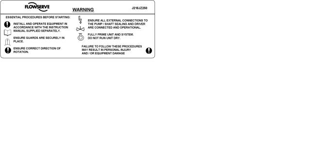
1.7.2 Safety labels
1.8 Specific machine performance
For performance parameters see section 1.5, Duty conditions. Where performance data has been supplied separately to the purchaser these should be obtained and retained with these User Instructions if required.
Bursting of liquid containing parts due to freezing must be avoided by draining or protecting the pump and ancillary systems.
Where there is the potential hazard of a loss of a seal barrier fluid or external flush, the fluid must be monitored.
If leakage of liquid to atmosphere can result in a hazard, the installation of a liquid detection device is recommended.
1.6.4.7 Maintenance to avoid the hazard
 CORRECT MAINTENANCE IS REQUIRED TO AVOID POTENTIAL HAZARDS WHICH GIVE A RISK OF EXPLOSION
The responsibility for compliance with maintenance instructions is with the plant operator.
To avoid potential explosion hazards during maintenance, the tools, cleaning and painting materials used must not give rise to sparking or adversely affect the ambient conditions. Where there is a risk from such tools or materials, maintenance must be conducted in a safe area.
It is recommended that a maintenance plan and schedule is adopted. (See section 6, Maintenance.)
1.9 Noise level
Attention must be given to the exposure of personnel to the noise, and local legislation will define when guidance to personnel on noise limitation is required, and when noise exposure reduction is mandatory. This is typically 80 to 85 dBA.
The usual approach is to control the exposure time to the noise or to enclose the machine to reduce emitted sound. You may have already specified a limiting noise level when the equipment was ordered, however if no noise requirements were defined, then attention is drawn to the following table to give an indication of equipment noise level so that you can take the appropriate action in your plant.
Pump noise level is dependent on a number of operational factors, flow rate, pipework design and acoustic characteristics of the building, and so the values given are subject to a 3 dBA tolerance and cannot be guaranteed.
Similarly the motor noise assumed in the “pump and motor” noise is that typically expected from standard and high efficiency motors when on load directly driving the pump. Note that a motor driven by an inverter may show an increased noise at some speeds.
Page 8 of 32 |
FLOWSERVE.COM |

CPXM and CPXRM USER INSTRUCTIONS ENGLISH 71569101 10-08
Motor size |
|
Typical sound pressure level LpA at 1 m reference 20 µPa, dBA |
|
|
||||||
3 550 r/min |
2 900 r/min |
1 750 r/min |
|
1 450 r/min |
||||||
and speed |
|
|||||||||
kW (hp) |
Pump |
Pump and |
Pump |
Pump and |
Pump |
Pump and |
|
Pump |
Pump and |
|
|
|
only |
motor |
only |
motor |
only |
motor |
|
only |
motor |
<0.55(<0.75) |
72 |
72 |
64 |
65 |
62 |
64 |
|
62 |
64 |
|
0.75 (1) |
72 |
72 |
64 |
66 |
62 |
64 |
|
62 |
64 |
|
1.1 (1.5) |
74 |
74 |
66 |
67 |
64 |
64 |
|
62 |
63 |
|
|
|
|
|
|
|
|
|
|
|
|
1.5 (2) |
74 |
74 |
66 |
71 |
64 |
64 |
|
62 |
63 |
|
2.2 (3) |
75 |
76 |
68 |
72 |
65 |
66 |
|
63 |
64 |
|
|
|
|
|
|
|
|
|
|
|
|
3 (4) |
75 |
76 |
70 |
73 |
65 |
66 |
|
63 |
64 |
|
4 (5) |
75 |
76 |
71 |
73 |
65 |
66 |
|
63 |
64 |
|
5.5 |
(7.5) |
76 |
77 |
72 |
75 |
66 |
67 |
|
64 |
65 |
7.5 (10) |
76 |
77 |
72 |
75 |
66 |
67 |
|
64 |
65 |
|
11(15) |
80 |
81 |
76 |
78 |
70 |
71 |
|
68 |
69 |
|
15 |
(20) |
80 |
81 |
76 |
78 |
70 |
71 |
|
68 |
69 |
18.5 (25) |
81 |
81 |
77 |
78 |
71 |
71 |
|
69 |
71 |
|
22 |
(30) |
81 |
81 |
77 |
79 |
71 |
71 |
|
69 |
71 |
|
|
|
|
|
|
|
|
|
|
|
30 |
(40) |
83 |
83 |
79 |
81 |
73 |
73 |
|
71 |
73 |
37 |
(50) |
83 |
83 |
79 |
81 |
73 |
73 |
|
71 |
73 |
|
|
|
|
|
|
|
|
|
|
|
Note: for 1 180 and 960 r/min reduce 1 450 r/min values by 2 dBA. For 880 and 720 r/min reduce 1 450 r/min values by 3 dBA.
If a pump unit only has been purchased for fitting with your own driver then the “pump only” noise levels in the table should be combined with the level for the driver obtained from the supplier. Consult Flowserve or a noise specialist if assistance is required in combining the values.
It is recommended that where exposure approaches the prescribed limit, then site noise measurements should be made.
The values are in sound pressure level LpA at 1 m (3.3 ft) from the machine, for “free field conditions over a reflecting plane”.
For estimating sound power level LWA (re 1 pW) then add 14 dBA to the sound pressure value.
2 TRANSPORT AND STORAGE
2.1 Consignment receipt and unpacking
Immediately after receipt of the equipment it must be checked against the delivery/shipping documents for its completeness and that there has been no damage in transportation. Any shortage and/or damage must be reported immediately to Flowserve Pump Division and must be received in writing within one month of receipt of the equipment. Later claims cannot be accepted.
Check any crate, boxes or wrappings for any accessories or spare parts that may be packed separately with the equipment or attached to side walls of the box or equipment.
Each product has a unique serial number. Check that this number corresponds with that advised and always quote this number in correspondence as well as when ordering spare parts or further accessories.
2.2 Handling
Boxes, crates, pallets or cartons may be unloaded using fork lift vehicles or slings dependent on their size and construction.
2.3 Lifting
 A crane must be used for all pump sets in excess of 25 kg (55 lb). Fully trained personnel must carry out lifting, in accordance with local regulations.
 No specific lifting points are provided for this complete machine (unless so specified). Any lifting points that can be seen are provided only for dismantling parts for servicing. Slings, ropes and other lifting gear should be positioned where they cannot slip and where a balanced lift is obtained.
Before lifting the driver alone, refer to the manufacturer’s instructions.
2.4 Storage
 Store the pump in a clean, dry location away from vibration. Leave piping connection covers in place to keep dirt and other foreign material out of pump casing. Turn pump at intervals to prevent brinelling of the bearings and the seal faces, if fitted, from sticking.
Page 9 of 32 |
FLOWSERVE.COM |

CPXM and CPXRM USER INSTRUCTIONS ENGLISH 71569101 10-08
The pump may be stored as above for up to 6 months. Consult Flowserve for preservative actions when a longer storage period is needed.
2.5 Recycling and end of product life
At the end of the service life of the product or its parts, the relevant materials and parts should be recycled or disposed of using an environmentally acceptable method and local requirements. If the product contains substances that are harmful to the environment, these should be removed and disposed of in accordance with current regulations. This also includes the liquids and/or gases that may be used in the "seal system" or other utilities.

 Make sure that hazardous substances are disposed of safely and that the correct personal protective equipment is used. The safety specifications must be in accordance with the current regulations at all times.
3 DESCRIPTION
3.1 Configurations
The pump is a modular designed centrifugal pump that can be built to achieve almost all chemical liquid pumping requirements. (See 3.2 and 3.3 below.)
3.2 Name nomenclature
The pump size will be engraved on the nameplate typically as below:
3.3 Design of major parts
3.3.1 Pump casing
The pump casing is designed with a horizontal centreline end inlet and a vertical centreline top outlet which makes it self venting.
For ease of maintenance, the pump is constructed so that pipe connectors do not have to be disturbed when internal maintenance is required.
3.3.2 Impeller/stubshaft
An open impeller with integral stubshaft is fitted. (On the CPXRM the impeller is recessed into the back of the casing with a wide front clearance.)
3.3.3 Adjustment stud
The adjustment stud is screwed into the end of the motor shaft. Adjustment of impeller front clearance is achieved by rotating the stubshaft on this stud.
3.3.4 Muff coupling
The muff coupling is investment cast in two halves (WCB steel). Notches at 30 degree increments around the circumference of the coupling assist in setting the impeller face clearance.
3.3.5 Pump bearings and lubrication
The pump uses the motor bearings to support and position the pump shaft. See motor instruction book for lubrication details.
80-50CPXM200
Nominal suction size in mm
Nominal discharge size in mm
Configuration – see 3.3.1 and 3.3.2 below
Nominal ISO maximum impeller diameter
The typical nomenclature above is the general guide to the CPXM configuration description. Identify the actual pump size and serial number from the pump nameplate. Check that this agrees with the applicable certification provided.
3.3.6 Seal housing
The seal housing has spigots between the motor pedestal and bearing housing for optimum concentricity.
A fully confined gasket forms the seal between the pump casing and the seal housing.
The seal housings designs provide improved performance of mechanical seals.
The design enables one of a number of sealing options to be fitted.
3.3.7 Shaft seal
The mechanical seal(s) attached to the stubshaft seals the pumped liquid from the environment.
3.3.8 Driver
The driver is a close-coupled electric motor featuring bearing location. This provides positive rotor assembly location to limit axial movement and allow accurate impeller setting.
Page 10 of 32 |
FLOWSERVE.COM |
 Loading...