


 Loading...
Device Description User Manual
Logix® MD+ Positioners with HART®

DD User Manual - Logix® 520MD+ Series Digital Positioner FCD-LGENSF0013-01
CONTENTS
DD MENU CHART .................................. |
3 |
8 |
AUXILIARY CARDS........................ |
20 |
||
GENERAL INFORMATION....................... |
6 |
8.1 |
AUXILIARY CARD 1 ID..................................................... |
20 |
||
|
|
|
8.2 |
AUXILIARY CARD 1 TYPE.................................................. |
20 |
|
INTRODUCTION .......................................................................... |
6 |
8.3 |
AUXILIARY CARD 1 DI SETUP ........................................... |
20 |
||
QUALIFIED PERSONNEL................................................................ |
6 |
8.4 |
AUXILIARY CARD 1 DO TRIGGER....................................... |
20 |
||
USING THIS DOCUMENT .............................................................. |
6 |
8.5 |
CALIBRATE MFC 1 ANALOG OUT...................................... |
21 |
||
TERMS CONCERNING SAFETY ........................................................ |
6 |
8.6 |
AUXILIARY CARD 2 ID..................................................... |
21 |
||
1 |
LONG TAG |
7 |
8.7 |
AUXILIARY CARD 2 TYPE.................................................. |
21 |
|
8.8 |
AUXILIARY CARD 2 DI SETUP |
22 |
||||
|
|
|
||||
2 |
TAG |
7 |
8.9 |
AUXILIARY CARD 2 DO TRIGGER....................................... |
22 |
|
8.10 CALIBRATE MFC 2 ANALOG OUT |
23 |
|||||
|
|
|
||||
3* |
FULL INITIAL SETUP ....................... |
7 |
|
|
|
|
3 |
STATUS ......................................... |
7 |
|
|
|
|
3.1 |
PRIORITY ALARM ............................................................. |
7 |
|
|
|
|
3.2 |
COMMAND DATA ............................................................ |
7 |
|
|
|
|
3.3 |
PRESSURES ..................................................................... |
7 |
|
|
|
|
3.4 |
HOUR METERS ................................................................ |
7 |
|
|
|
|
3.5 |
TEMPERATURE HISTORY.................................................... |
7 |
|
|
|
|
3.6 |
HEALTH DATA ................................................................. |
8 |
|
|
|
|
3.7 |
DIAGNOSTIC VALUES ........................................................ |
8 |
|
|
|
|
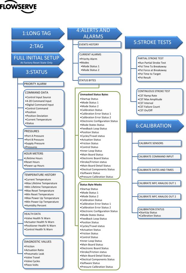
4 |
ALERTS AND ALARMS.................... |
9 |
|
|
|
|
4.1 |
EVENTS HISTORY.............................................................. |
9 |
|
|
|
|
4.2 |
CURRENT ALARMS ........................................................... |
9 |
|
|
|
|
4.3 |
STATUS BYTES ................................................................. |
9 |
|
|
|
|
5 |
STROKE TESTS............................ |
11 |
|
|
|
|
5.1 |
PARTIAL STROKE TEST..................................................... |
11 |
|
|
|
|
5.2 |
CONTINUOUS STROKE TEST ............................................. |
11 |
|
|
|
|
6 |
CALIBRATION .............................. |
12 |
|
|
|
|
6.1 |
CALIBRATE SENSORS....................................................... |
12 |
|
|
|
|
6.2 |
CALIBRATE COMMAND INPUT .......................................... |
12 |
|
|
|
|
6.3 |
CALIBRATION DATES AND TIMES....................................... |
12 |
|
|
|
|
6.4 |
CALIBRATE MFC ANALOG OUT 1 ..................................... |
12 |
|
|
|
|
6.5 |
CALIBRATE MFC ANALOG OUT 2 ..................................... |
12 |
|
|
|
|
6.6 |
CALIBRATION STATUS ..................................................... |
12 |
|
|
|
|
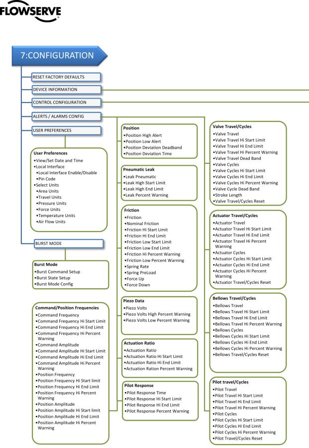
7 |
CONFIGURATION ......................... |
13 |
|
|
|
|
7.1 |
RESET FACTORY DEFAULTS .............................................. |
13 |
|
|
|
|
7.2 |
DEVICE INFORMATION .................................................... |
13 |
|
|
|
|
7.3 |
CONTROL CONFIG .......................................................... |
14 |
|
|
|
|
7.4 |
ALERTS / ALARMS CONFIG .............................................. |
16 |
|
|
|
|
7.5 |
USER PREFERENCES ........................................................ |
19 |
|
|
|
|
7.6 |
BURST MODE................................................................ |
20 |
|
|
|
|
© Flowserve Corporation |
2 |
DD User Manual - Logix® 520MD+ Series Digital Positioner FCD-LGENSF0013-01
DD MENU CHART
© Flowserve Corporation |
3 |
DD User Manual - Logix® 520MD+ Series Digital Positioner FCD-LGENSF0013-01
© Flowserve Corporation |
4 |

DD User Manual - Logix® 520MD+ Series Digital Positioner FCD-LGENSF0013-01
© Flowserve Corporation |
5 |

DD User Manual - Logix® 520MD+ Series Digital Positioner FCD-LGENSF0013-01
GENERAL INFORMATION
Introduction
This document provides detailed information about the function of the Logix 520MD+ Device Description (DD). The DD follows the protocol provided by the HART Communication Foundation. For more information about downloading, installing and using HART DDs, visit
http://www.hartcomm.org/
Qualified Personnel
Qualified personnel are people who, on account of their training, experience, instruction and their knowledge of relevant standards, specifications, accident prevention regulations and operating conditions, have been authorized by those responsible for the safety of the plant to perform the necessary work and who can recognize and avoid possible dangers.
In using this software, the position and operation of the related valves can be affected. Product users and maintenance personnel should thoroughly review the effects of any functions before applying those functions.
Using This Document
The features listed below are numbered to correspond to their location in the DD menu tree. Some menu items may not be available depending on positioner upgrade status and the presence of auxiliary cards.
Terms Concerning Safety
The safety terms DANGER, CAUTION and NOTE are used in these instructions to highlight particular dangers and/or to provide additional information on aspects that may not be readily apparent.
To avoid possible injury to personnel or damage to valve parts, DANGER and CAUTION notes must be strictly followed. Modifying this product, substituting non-factory parts or using maintenance procedures other than outlined could drastically affect performance and be hazardous to personnel and equipment, and may void existing warranties.
NOTE: indicates and provides additional technical information, which may not be very obvious even to qualified personnel.
 CAUTION: Indicates that minor personal injury and/or property damage can occur if proper precautions are not taken.
DANGER: Indicates that death, severe personal injury and/or substantial property damage can occur if proper precautions are not taken.
© Flowserve Corporation |
6 |

|
DD User Manual - Logix® 520MD+ Series Digital Positioner FCD-LGENSF0013-01 |
|
1 LONG TAG |
The humidity of the positioner’s main circuit board in relative |
|
percent (RH). |
||
|
Set the HART long tag. (For HART 6 only.)
2 TAG
Set the HART tag.
3* FULL INITIAL SETUP
Set basic values and perform calibrations required for positioner to control.
*This menu item is only available when the positioner in in Factory Reset state.
3 STATUS
View basic information about the current status of the positioner including basic on-line diagnostics.
3.1Priority Alarm
View the highest priority alarm. For a complete list of current alarms, see Alarms and Alerts.
3.2Command Data
View command and position information.
3.2.1Control Input Source
Select either analog or digital command input source.
3.2.24-20 Command Input
View the analog command input value.
3.2.3Digital Command Input
Set the digital command input value.
3.2.4Control Command
View the final command after Characterization, Soft Limits, and Tight Shut-Off effects are applied.
3.2.5Position
View the position of the valve.
3.2.6Position Deviation
View the difference between the Control (Final) Command and the Position.
3.2.7Current Temperature
The temperature of the positioner’s main circuit board.
3.2.8Current Humidity
©Flowserve Corporation
3.3Pressures
View the pressure sensor values. Advanced or Pro diagnostics are required.
3.3.1Port A Pressure
View the pressure at port A.
3.3.2Port B Pressure
View the pressure at port B.
3.3.3Supply Pressure
View the supply pressure.
3.3.4Pressures
View a graph of Port A, Port B, and Supply pressures. (EDD only.)
3.4Hour Meters
View the number of hours the positioner has been in operation.
3.4.1Lifetime Hours
View the total number of hours the positioner has been in operation.
3.4.2Reset Hours
View the number of hours the positioner has been in operation since the last factory reset was performed.
3.4.3Power up Hours
View the number of hours the positioner has been in operation since the last time it was powered up.
3.5Temperature History
View the positioner temperature and humidity information.
3.5.1Current Temperature
View the current temperature inside the positioner.
3.5.2Max Lifetime Temperature
View the maximum temperature the positioner has ever seen.
3.5.3Min Lifetime Temperature
View the minimum temperature the positioner has ever seen.
3.5.4Max Reset Temperature
View the maximum temperature the positioner has seen since the last factory reset was performed.
3.5.5Min Reset Temperature
7

DD User Manual - Logix® 520MD+ Series Digital Positioner FCD-LGENSF0013-01
View the minimum temperature the positioner has seen since the last factory reset was performed.
3.5.6Max Power Up Temperature
View the maximum temperature the positioner has seen since the last time the positioner was powered up.
3.5.7Min Power Up Temperature
View the minimum temperature the positioner has seen since the last time the positioner was powered up.
3.5.8Humidity Percent
View the current relative humidity inside the positioner.
View the pneumatic leakage of the actuator. This value does not include normal air consumption.
3.7.4Valve Travel
View the amount the valve has traveled in percent of total stroke length.
3.7.5Valve Cycles
View the number of cycles the valve has travelled. This is the number of times the valve has changed directions twice.
3.7.6Piezo Volts
View the voltage supplied to the piezo element in the positioner's pilot relay. This should typically be between 0 and 24 VDC.
3.6Health Data
View the warning level for each category. The 520MD+ positioner monitors the conditions that affect the ability of the valve to respond. As these conditions worsen, a warning level is shown. A low value such as 0% indicates no warning. A high value such as 90% indicates the ability to control may be impaired soon. A value of 100 indicates that the valve may no longer be responsive.
3.6.1Valve Health % Warning
The warning value from 0 to 100% based on warnings and alarms related to valve health such as friction. A lower value indicates less serious issues.
3.6.2Actuator Health % Warning
The warning value from 0 to 100% based on warnings and alarms related to actuator health such as supply pressure. A lower value indicates less serious issues.
3.6.3Positioner Health % Warning
The warning value from 0 to 100% based on warnings and alarms related to positioner health such as circuit board malfunction. A lower value indicates less serious issues.
3.6.4Control Health % Warning
The warning value from 0 to 100% based on warnings and alarms related to control health such as deviation. A lower value indicates less serious issues.
3.7Diagnostic Values
View basic diagnostic information. Pro diagnostics are required.
3.7.1Friction
View the friction of the valve and actuator assembly.
3.7.2Actuation Ratio
View the effort required to move the valve in the direction that compresses the spring. The ratio is the force required to overcome friction, spring, and process load forces over the force available from the current supply pressure.
3.7.3Pneumatic Leak
© Flowserve Corporation |
8 |
Loading...