


 Loading...
Argus
Ball valves
Service Manual
Types:
EK/71
EK/74
FK/75
FK/76
FK79
FK/79/F
FK/492
HK/35
MW/22
Experience In Motion

Argus
Table of contents
Table of contents |
|
Designed Use ............................................................ |
3 |
Application Areas................................................................... |
3 |
Design ................................................................................... |
3 |
Installation ............................................................................. |
3 |
Impermissible Operating Procedures..................................... |
3 |
Maintenance .......................................................................... |
3 |
Safety Information..................................................... |
3 |
Safety Standards....................................................... |
5 |
Pressure-Temperature Diagrams ............................ |
5 |
Delivery/Storage........................................................ |
5 |
Check on Delivery.................................................................. |
5 |
Storage of the Ball Valves ..................................................... |
5 |
Transport ................................................................... |
6 |
Installing the Flanged Connection .......................... |
7 |
Installing the Ball Valve.......................................................... |
7 |
Connecting the first Flange.................................................... |
7 |
Connecting the second Flange .............................................. |
7 |
Installing the Welding Connection .......................... |
8 |
Installing the Ball Valve.......................................................... |
8 |
Welding the Connections....................................................... |
8 |
Start-up ...................................................................... |
9 |
Actuating the Ball Valve......................................................... |
9 |
Open Position of the Ball Valves............................................ |
9 |
Maintenance ............................................................ |
10 |
Type EK/71.......................................................................... |
10 |
Disassembly ..................................................................... |
10 |
Exchanging the Stem Sealing........................................... |
10 |
Type FK/74 .......................................................................... |
11 |
Disassembly ..................................................................... |
11 |
Exchanging the Stem Sealing........................................... |
11 |
Type FK/75 .......................................................................... |
12 |
Disassembly ..................................................................... |
12 |
Exchanging the Stem Sealing........................................... |
12 |
Type FK/76 .......................................................................... |
13 |
Disassembly..................................................................... |
13 |
Exchanging the Stem Sealing .......................................... |
13 |
Type FK/78.......................................................................... |
14 |
Disassembly..................................................................... |
14 |
Exchanging the Stem Sealing .......................................... |
14 |
Reassembly ..................................................................... |
14 |
Type FK/79.......................................................................... |
15 |
Disassembly..................................................................... |
15 |
Exchanging the Stem Sealing .......................................... |
15 |
Type FK/79/F ...................................................................... |
16 |
Disassembly..................................................................... |
16 |
Exchanging the Stem Sealing .......................................... |
16 |
Type FK/492........................................................................ |
17 |
Disassembly..................................................................... |
17 |
Type HK/35 ......................................................................... |
18 |
Disassembly..................................................................... |
18 |
Exchanging the Stem Sealing .......................................... |
18 |
Reassembly ..................................................................... |
18 |
Type MW/22........................................................................ |
19 |
Disassembly..................................................................... |
19 |
Reassembly ..................................................................... |
19 |
Accessories ............................................................. |
20 |
Stuffing Box Assembly ........................................................ |
20 |
Re-tensioning the Seal ..................................................... |
20 |
Changing the Seals .......................................................... |
20 |
Drain Plug ........................................................................... |
21 |
Drain and Ventilation Safety Plug........................................ |
21 |
Supplementary Equipment.................................................. |
22 |
Valve Actuators (Adjusting Range 90°) ............................ |
22 |
Position Control Systems ................................................. |
22 |
Gearbox with Hand Wheel ............................................... |
22 |
Position Limit Switch ........................................................ |
22 |
Underfloor Fittings ............................................................ |
22 |
Metal Seals ...................................................................... |
22 |
Safety Devices ................................................................. |
22 |
Forced Shut-off Circuits.................................................... |
22 |
Safety Control Circuits...................................................... |
22 |
Heating Jackets................................................................ |
22 |
Secondary Sealing Systems ............................................ |
22 |
2

Argus
Designed Use
Designed Use
Series EK, FK and HK ball valves are used as shut-off devices in pipelines associated with processing, handling and transporting liquid or gaseous as well as solid materials.
Application Areas
Chemical industries
Petrochemical industries
Gas industries
Maintenance
Ball valves are maintenance-free. It is advisable, however, to actuate them at least once or twice a year.
Safety Information
Information
Please read the safety instructions carefully!
Design
Type EK ball valves have a unibody end-entry with an axial screw-type connection.
FK and HK ball valves have a two-piece split-body de-sign with flanged connection in between the two halves.
General instructions
Installation and maintenance may be performed only by trained, qualified personnel.
The media to be used must comply with the ARGUS technical specifications in order to exclude any harmful effects on the seals. Contact ARGUS for further information.
Installation
The ball valves can be installed in pipelines by means of flanged connections or by welding.
Material requirements for welding must be ascertained from the manufacturer and must comply with customer specifications.
The ball valves are designed for a normal load during service in pipelines. Under certain preconditions, the ball valves can also be used for more severe operating conditions, although in such cases, the manufacturer should be consulted in advance.
Impermissible Operating Procedures
To exclude any harmful effects on the seals, the substance to be used must comply with the ARGUS technical specifications.
Consult ARGUS beforehand if necessary.
The combination of medium temperature and pressure are decisive factors for the choice of sealant materials.
Danger!
It is essential that the limit values are not exceeded; these values can be taken from ARGUS diagrams.
Warning!
The specified service pressures and temperatures must not be exceeded, even as individual loads.
Caution!
The user is responsible for ensuring compliance with the guidelines, regulations, safety standards and laws applicable to the use of these ball valves.
Danger!
It is essential that the limit values are not exceeded; these values can be taken from ARGUS diagrams (see Section Designed Use).
Warning!
The specified service pressures and temperatures must not be exceeded, even as individual loads (see Chapter Designed Use).
Caution!
The user is responsible for ensuring compliance with the guidelines, regulations, safety standards and laws applicable to the use of these ball valves (see Chapter Designed Use).
Danger!
Local safety regulations must be com-plied with for transport to the place of installation. Make sure that the valves cannot tilt or slip in any way (see Chapter Transport).
Warning!
After installation, the pipeline and ball valve must be rinsed through before the ball valve is actuated (see Chapter Installing the Flanged Connection).
Danger!
The local welding regulations and specifications must be complied with when carrying out welding work (see Chapter Installing the Welding Connection).
3
Argus
Safety Information
Caution!
Use temperature measuring strips to check that the temperature does not rise beyond the permissible limits (100°C). The strips must be fitted to the connection near the soft inserts (see Chapter Installing the Welding Connection).
Caution!
The temperature measurement strip must be monitored constantly throughout the welding work (see Chapter Installing the Welding Connection).
Caution!
If any change of colour is noticed, the welding work must be interrupted immediately and the weld allowed cooling (see Chapter Installing the Welding Connection).
Caution!
Before start-up of the ball valve, the pipeline must be rinsed (see Chapter Installing the Welding Connection).
Warning!
Before start-up of the ball valve a leak test must be performed (see Chapter Start-up).
Warning!
The ball valve must be set to the OPEN position in order to avoid any damage (see Chapter Startup).
Danger!
For safety reasons, the position of the wrench must clearly reflect the OPEN position of the ball valve (see Chapter Start-up).
Danger!
Do not disassemble the valve under pressure. Before disassembly operate valve so that possible pressure behind the ball may escape (see Chapter Maintenance).
Caution!
Do not loosen the fixing nuts (see Chapter Stuffing Box Assembly).
Danger!
The ball valve must be depressurized! To release encaptured pressure, turn ball.
Take care of any hazardous materials that might escape! Risk of explosion, fire and acid burn! (see Chapter Stuffing Box Assembly)
Danger!
De-pressurize the ball valve by turning the ball at 90° before removing drain and ventilation plug (see Chapter Drain Plug).
Danger!
Care must be taken when hazardous materials are involved!
Risk of explosion, fire and acid burn! (see Chapter Drain Plug)
Warning!
The plug may only be opened but not unscrewed by force (see Chapter Drain and Ventilation Safety Plug).
Warning!
Keep away from the outlet! Risk of injury! See Chapter Drain and Ventilation Safety Plug.
Warning!
The medium is ejected sideways! See Chapter Drain and Ventilation Safety Plug.
4
Argus
Safety Standards
Safety Standards
Depending on the type and pressure rating, ARGUS ball valves are designed to conform with national and international regulations, such as DIN 3357, AD and VdTÜV-Merkblätter, TRbF, TRGL, TRD, TRG, DVGW, BS 5351, API6D and ANSI B16.34.
Design certifications and DIN-DVGW certificates are available. The acceptance of the fittings is carried out according to DIN 3230 or specific customer requirements.
The reliability of fittings sealed with soft materials in case of fire, or even at temperatures above +600 °C is confirmed by the Fire-Safe Certificate and can be verified using BS 6755and/or API 607.
Authorized testing institutions such as TÜV, German Lloyd, BS, Lloyds Register, DNV, Bureau Veritas, etc., carry out further tests on behalf of ARGUS or customers at regular intervals.
Compliance with Quality Assurance procedures under ISO 9001 was certified by DQS (German Society for Quality Assurance).
Delivery/Storage
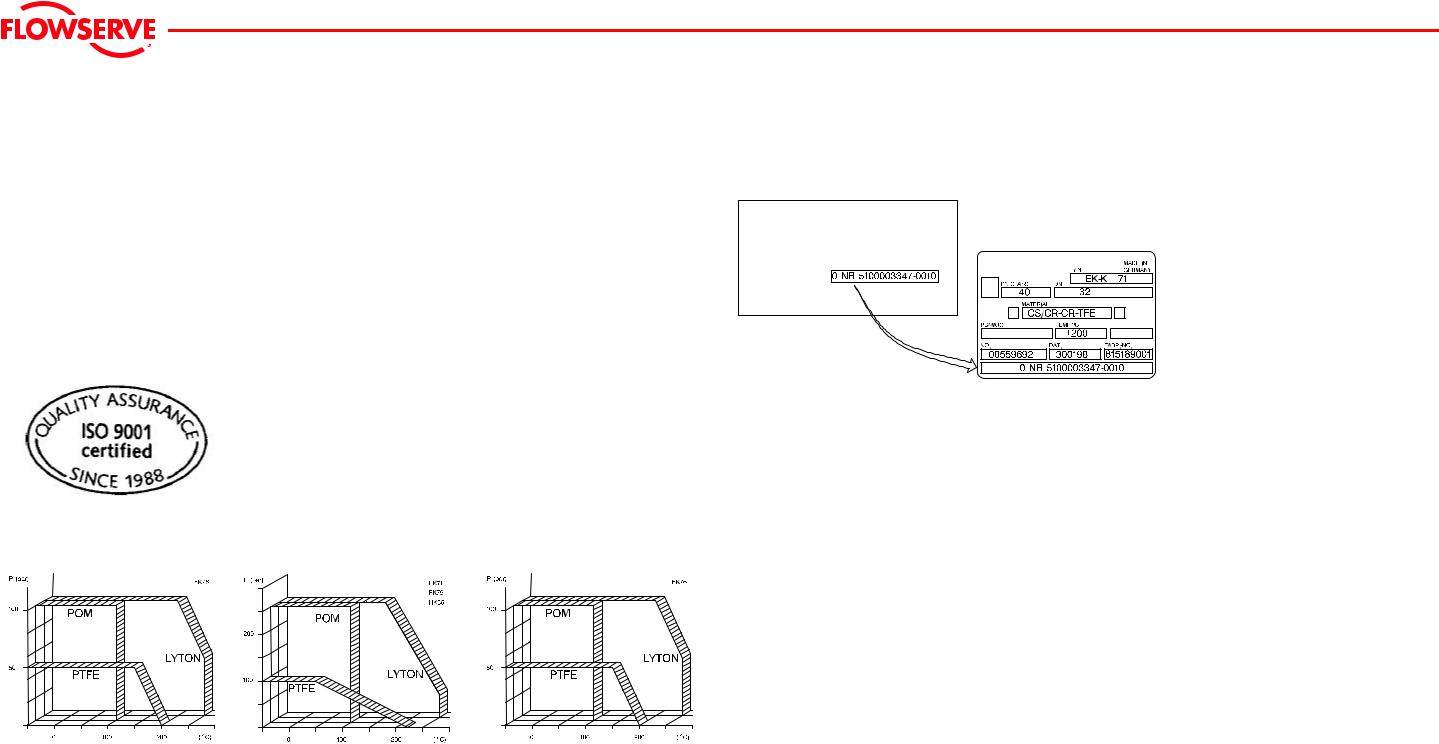
Check on Delivery
Lieferschein |
delivery note |
bordereau de livraison |
Bestellnummer: |
order number: |
numØro de commande: |
0000-00-002
At delivery compare the order number on the delivery note with the number on the rating plate (see figure above). In addition check that the correct item has been delivered and that the delivery is complete.
Complaints submitted at a later date cannot be accepted.
Pressure-Temperature Diagrams
Storage of the Ball Valves
Ball valve must be set to OPEN.
Store ball valve in dry rooms.
Protect ball valve against dirt.
Protective caps must remain in position until the valves are finally installed.
FK76-01-001 |
0000-01-001 |
0000-01-002 |
5
Argus
Transport
Transport
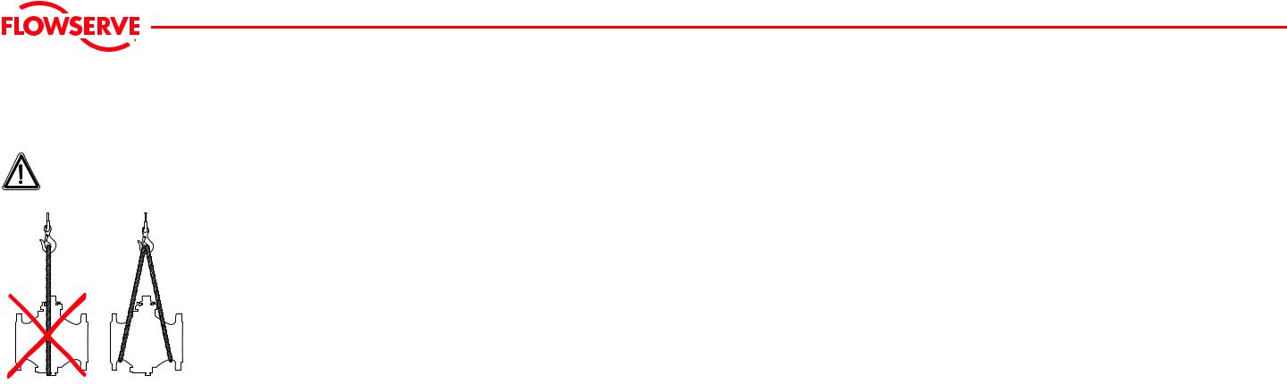
Danger!
Local safety regulations must be complied with for transport to the place of installation.
Make sure that the valves cannot tilt or slip in any way (see figure below).
0000-00-002
The user is liable for any damage resulting from incorrect transport.
6
Installing the Flanged Connection
Argus
Installing the Flanged Connection
Installing the Ball Valve
0003-00-002 |
0003-00-004 |
0003-00-001 |
0003-000-003 |
0005-00-001 |
0003-00-005 |
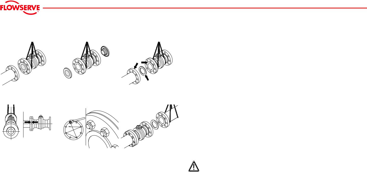
fTransport the ball valve safely to the installation site using suitable hoisting gear dimensioned in accordance with the weight and size of the ball valve (Figure 0003-00-002).
fRemove protective caps (Figure 0003-00-004).
fClean pipeline, seal and connecting flange (Figure 0003-00-001).
Connecting the first Flange
fPosition the seal carefully.
fSecure the ball valve to the pipeline flange with a few bolts
fCheck that the ball valve and gaskets are correctly located in relation to the pipeline flange.
fCheck the alignment of the ball valve and pipeline (Figure 0003-000-003).
fCorrect any discrepancies.
fTighten the bolts crosswise (Figure 0005-00-001).
Connecting the second Flange
fThe second flange is installed in the same way as the first flange (Figure 0003-00-005).
fTighten the bolts crosswise (Figure 0005-00-001).
fAfter installation, check for any leaks.
fAfter installation, the pipeline and ball valve must be rinsed through before the ball valve is actuated.
Warning!
After installation, the pipeline and ball valve must be rinsed through before the ball valve is actuated.
7
Loading...