


PLEUGER® standard submersible motor pumps
Submersible motor pumps with water filled motor for deep-well installation
PCN=71569293 01-13 (E) (Based on 1042.277/7.) Original instructions.
USER INSTRUCTIONS
Installation
Operation
Maintenance
 These instructions must be read prior to installing, operating, using and maintaining this equipment.

PLEUGER STANDARD USER INSTRUCTIONS ENGLISH 71569293 01-13
CONTENTS |
|
|
|
|
Page |
1 INTRODUCTION AND SAFETY............................ |
3 |
|
1.1 |
General ........................................................... |
3 |
1.2 |
CE marking and approvals.............................. |
3 |
1.3 |
Disclaimer ....................................................... |
3 |
1.4 |
Copyright......................................................... |
3 |
1.5 |
Duty conditions................................................ |
3 |
1.6 |
Safety .............................................................. |
4 |
2 TRANSPORT AND STORAGE.............................. |
9 |
|
2.1 |
Consignment receipt and unpacking............... |
9 |
2.2 |
Handling and lifting.......................................... |
9 |
2.3 |
Storage.......................................................... |
10 |
2.5 |
Recycling and end of product life.................. |
10 |
3 DESCRIPTION .................................................... |
10 |
|
3.1 |
Technical data ............................................... |
10 |
3.2 |
Delivery contents........................................... |
10 |
3.3 |
General data ................................................. |
11 |
3.4 |
General description ....................................... |
11 |
3.5 |
Submersible motor ........................................ |
12 |
3.6 |
Pump and check valve .................................. |
13 |
4 INSTALLATION.................................................... |
14 |
|
4.1 |
Hydraulic installation ..................................... |
14 |
4.2 |
General advice for installation....................... |
14 |
4.3 |
Flexible hose riser pipe ................................. |
14 |
4.4 |
Centralizers ................................................... |
14 |
4.5 |
Checks before installation ............................. |
14 |
4.6 |
Installation of pre-assembled pump units ..... |
15 |
4.7 |
Riser pipes with flange connections.............. |
15 |
4.8 |
Riser pipe with pipe socket ........................... |
15 |
4.9 |
Assembly of submersible motor pumps |
|
|
before installation........................................ |
15 |
5 ELECTRICAL CONNECTIONS ........................... |
16 |
|
5.1 |
Motor ............................................................. |
16 |
5.2 |
Protective measures against |
|
|
shock-hazard voltage.................................. |
16 |
5.3 |
Motor protection ............................................ |
17 |
5.4 |
Short circuit protection .................................. |
17 |
5.5 |
Motor connection diagrams........................... |
18 |
5.6 |
Adjustments for soft-starter and |
|
|
soft stop devices ......................................... |
20 |
5.7 |
Operation of submersible motors with |
|
|
static frequency converter........................... |
20 |
5.8 |
Resistance sensor PT100 (RTD) .................. |
21 |
|
|
Page |
6 MOTOR FILLING ................................................ |
21 |
|
6.1 |
Antifreeze ...................................................... |
21 |
6.2 |
Type of use ................................................... |
22 |
6.3 |
Filling quantities ............................................ |
22 |
6.4 |
Accessories and hardware for filling |
|
|
and topping up............................................ |
22 |
6.5 |
General information about filling ................... |
22 |
6.6 |
Filling instructions ......................................... |
23 |
7 COMMISSIONING, START-UP |
|
|
AND SHUTDOWN........................................... |
31 |
|
7.1 |
Commissioning ............................................. |
31 |
7.2 |
Operation ...................................................... |
31 |
7.3 |
Switching off the unit..................................... |
32 |
8 MAINTENANCE .................................................. |
32 |
|
8.1 |
General information ...................................... |
32 |
8.2 |
Pump units .................................................... |
32 |
8.3 |
Measuring insulation..................................... |
32 |
8.4 |
Removal of the pump unit............................. |
33 |
8.5 |
Overhaul of the pump unit ............................ |
33 |
9 FAULTS; CAUSES AND REMEDIES .................. |
35 |
|
10 CERTIFICATION ............................................... |
37 |
|
Page 2 of 40 |
flowserve.com |

PLEUGER STANDARD USER INSTRUCTIONS ENGLISH 71569293 01-13
1 INTRODUCTION AND SAFETY
1.1 General
 These instructions must always be kept close to the product's operating location or directly with the product.
Flowserve products are designed, developed and manufactured with state-of-the-art technologies in modern facilities. The unit is produced with great care and commitment to continuous quality control, utilising sophisticated quality techniques, and safety requirements.
Flowserve is committed to continuous quality improvement and being at service for any further information about the product in its installation and operation or about its support products, repair and diagnostic services.
These instructions are intended to facilitate familiarization with the product and its permitted use. Operating the product in compliance with these instructions is important to help ensure reliability in service and avoid risks. The instructions may not take into account local regulations; ensure such regulations are observed by all, including those installing the product. Always coordinate repair activity with operations personnel, and follow all plant safety requirements and applicable safety and health laws and regulations.
 These instructions should be read prior to installing, operating, using and maintaining the equipment in any region worldwide. The equipment must not be put into service until all the conditions relating to safety noted in the instructions, have been met.
1.2 CE marking and approvals
It is a legal requirement that machinery and equipment put into service within certain regions of the world shall conform with the applicable CE Marking Directives covering Machinery and, where applicable, Low Voltage Equipment, Electromagnetic Compatibility (EMC), Pressure Equipment Directive (PED), minimum efficiency for some water pumps (Ecodesign) and Equipment for Potentially Explosive Atmospheres (ATEX).
Where applicable, the Directives and any additional Approvals, cover important safety aspects relating to machinery and equipment and the satisfactory provision of technical documents and safety instructions.
Where applicable this document incorporates information relevant to these Directives and Approvals. To confirm the Approvals applying and if the product is CE marked, check the serial number plate markings and the Certification. (See section 9, Certification.)
1.3 Disclaimer
Information in these User Instructions is believed to be reliable. In spite of all the efforts of Flowserve Corporation to provide sound and all necessary information the content of this manual may appear insufficient and is not guaranteed by Flowserve as to its completeness or accuracy.
Flowserve manufactures products to exacting International Quality Management System Standards as certified and audited by external Quality Assurance organisations. Genuine parts and accessories have been designed, tested and incorporated into the products to help ensure their continued product quality and performance in use. As Flowserve cannot test parts and accessories sourced from other vendors the incorrect incorporation of such parts and accessories may adversely affect the performance and safety features of the products. The failure to properly select, install or use authorised Flowserve parts and accessories is considered to be misuse. Damage or failure caused by misuse is not covered by the Flowserve warranty. In addition, any modification of Flowserve products or removal of original components may impair the safety of these products in their use.
The operational safety of the delivered unit is only guaranteed for use according to the limitations described in section 3.1, Technical data. The limits given in the data sheet may not be exceeded.
1.4 Copyright
All rights reserved. No part of these instructions may be reproduced, stored in a retrieval system or transmitted in any form or by any means without prior permission of Flowserve.
1.5 Duty conditions
This product has been selected to meet the specifications of your purchaser order. The acknowledgement of these conditions has been sent separately to the Purchaser. A copy should be kept with these instructions.
 The product must not be operated beyond the parameters specified for the application.
If there is any doubt as to the suitability of the product for the application intended, contact Flowserve for advice, quoting the serial number.
Page 3 of 40 |
flowserve.com |

PLEUGER STANDARD USER INSTRUCTIONS ENGLISH 71569293 01-13
If the conditions of service on your purchase order are going to be changed (for example liquid pumped, temperature or duty) it is requested that the user seeks the written agreement of Flowserve before start up.
1.6 Safety
1.6.1 Summary of safety markings
These User Instructions contain specific safety markings where non-observance of an instruction would cause hazards. The specific safety markings are:
 This symbol indicates electrical safety instructions where non-compliance will involve a high risk to personal safety or the loss of life.
 This symbol indicates safety instructions where non-compliance would affect personal safety and could result in loss of life.
 This symbol indicates “hazardous and toxic fluid” safety instructions where non-compliance would affect personal safety and could result in loss of life.
 This symbol indicates safety instructions where non-compliance will involve some risk to safe operation and personal safety and would damage the equipment or property.
 This symbol indicates explosive atmosphere zone marking according to ATEX. It is used in safety instructions where non-compliance in the hazardous area would cause the risk of an explosion.
 This symbol is used in safety instructions to remind not to rub non-metallic surfaces with a dry cloth; ensure the cloth is damp. It is used in safety instructions where non-compliance in the hazardous area would cause the risk of an explosion.
 This sign is not a safety symbol but indicates an important instruction in the assembly process.
1.6.2 Personnel qualification and training
All personnel involved in the operation, installation, inspection and maintenance of the unit must be qualified to carry out the work involved. If the personnel in question do not already possess the necessary knowledge and skill, appropriate training and instruction must be provided. If required the operator may commission the manufacturer/supplier to provide applicable training.
Always coordinate repair activity with operations and health and safety personnel, and follow all plant safety requirements and applicable safety and health laws and regulations.
1.6.3 Safety action
This is a summary of conditions and actions to help prevent injury to personnel and damage to the environment and to equipment. For products used in potentially explosive atmospheres section 1.6.4 also applies.
 NEVER DO MAINTENANCE WORK WHEN THE UNIT IS CONNECTED TO POWER
Before maintenance and repair work is started the motor of the pump unit must first be completely isolated from the electrical power supply.
The procedure to shut down the unit described in section 7.3, Switching off the unit, must be followed without fail.
 Danger from electricity must be eliminated. (For details see, for example, the regulations of the VDE and local power supply companies.)
 GUARDS MUST NOT BE REMOVED WHILE THE PUMP IS IN OPERATION
 HANDLING COMPONENTS
Many precision parts have sharp corners and the wearing of appropriate safety gloves and equipment is required when handling these components. To lift heavy pieces above 25 kg (55 lb) use a crane appropriate for the mass and in accordance with current local regulations.
 DISMOUNTING PUMP UNITS
Before dismounting one pump unit, the pump must be separated from the motor and drained. In case of dangerous delivery fluids, suitable safety measures must be made.
 THERMAL SHOCK
Rapid changes in the temperature of the liquid within the pump can cause thermal shock, which can result in damage or breakage of components and should be avoided.
 HOT (and cold) PARTS
If hot or cold components, or heater or cooler units, can cause a danger for the operating staff or persons in the immediate vicinity, measures must be taken to prevent possible contact, eg by protective gratings.
Page 4 of 40 |
flowserve.com |

PLEUGER STANDARD USER INSTRUCTIONS ENGLISH 71569293 01-13
If complete protection is not possible, access to such devices must be limited to the maintenance staff who must be informed specifically about the special dangers by warnings and corresponding signs.
The measures listed above must be applied if the temperatures in a limited access zone exceed
80 ºC (175 ºF) or fall below -5 ºC (23 ºF), or if the regional limit values are exceeded.
 ADDITIONAL SAFETY NOTES
In addition to the safety notes listed in the main Safety section, special safety notes in all other sections must also be observed, eg those for private use.
 COMMISSIONING
Prior to each commissioning after installation, maintenance or repair, follow the instructions and notes in section 8, Commissioning, switching on, operation and switching off.
Notes directly attached to the unit must be observed without fail. These include:
Marking of connections
Rating plate
Rotational direction


 HAZARDOUS LIQUIDS
Units handling hazardous liquids must be decontaminated.


 INFLAMMABLE FLUIDS
When the pump is handling hazardous liquids care must be taken to avoid exposure to the liquid by appropriate siting of the pump, limiting personnel access and by operator training. If the liquid is flammable and or explosive, strict safety procedures must be applied.
When pumping dangerous fluids, no packing seals must be used.
 PREVENT EXCESSIVE EXTERNAL PIPE LOAD
In horizontally arranged pump units, the pump must not be used as support for suction or pressure pipework. Arrange compensators in such a way that the forces caused by internal pressure do not act upon the pump flange unless approved in writing by Flowserve.
 ROTATIONAL DIRECTION OF THE MOTOR
The rotational direction of each motor can be found in the data sheet and or the connection data sheet.
As testing the rotational direction by short startup in dry conditions is not permitted and as by design the
rotational direction of the motor cannot be determined when the pump unit is completely mounted, the rotating field of the power supply must be known. If necessary, it must be determined using a rotating field measurement device.
If the pump unit is operated with incorrect rotational direction, the delivery output is reduced and pump damage is possible.
 OPERATION OF THE PUMP UNIT The pump unit may only be operated if the unit is completely mounted, the motor is completely filled with the prescribed amount of filling fluid and it is submerged sufficiently into the delivery medium.
Never let the submersible motor pump run dry.
Switching on, including for test purposes, is never allowed if the pump is not submerged.
For the minimum submersion depth in the delivery medium, refer to the provided data sheet or ask Flowserve.
Non-observance can cause the following dangers:
Failure of important system functions
Failure of prescribed methods for maintenance and upkeep
Danger to persons due to electrical, mechanical or chemical impact
Danger to the environment by leakage when delivering hazardous media
 OPERATION OF THE PUMP UNIT Operation with a flow volume that is above average or does not cause counter-pressure to the pump can cause a motor overload and cavitation in the pump. Low flow rates can cause shortened service life of the pump, overheating of the pump, instability, cavitation and vibration.
The duty point for which the pump unit has been designed can be found in the data sheet of the pump.
 SWITCHING ON THE PUMP UNIT After having completely installed the pump unit, close the outlet valve apart for a small gap to bleed the riser pipeline. (If the system is equipped with an airrelease valve at the highest point of the riser pipeline, the outlet valve remains closed.) After switching on, the pressure at the pressure gauge must be higher than the pumping head specified in the data sheet, minus the water depth.
Page 5 of 40 |
flowserve.com |
PLEUGER STANDARD USER INSTRUCTIONS ENGLISH 71569293 01-13
Because of the risk of motor overload, S-series units (pumps with axial impellers) must never be started against a closed slider!
In order to avoid overheating the pump, a pump must never be operated for more than 2 minutes against a closed outlet valve.
In the time during which the empty riser is filled, the ampere meter can display a higher current after switch-on than specified in the data sheet, even after the starting current has subsided.
Afterwards, the operating current must be lower than the maximum permitted current as specified in the data sheet.
SLOWLY open the outlet valve so as to not cause overload to the well due to excessive delivery flow.
Open the slider slowly until the ampere meter displays the operating current as specified in the data sheet.
After reaching the operating point for which the unit has been designed, the current intake must approximately match the one specified in the data sheet.
1.6.4 Products used in potentially explosive atmospheres
 Measures are required to:
Avoid excess temperature
Prevent build up of explosive mixtures
Prevent the generation of sparks
Prevent leakages
Maintain the pump to avoid hazard
The following instructions for pumps and pump units when installed in potentially explosive atmospheres must be followed to help ensure explosion protection. For ATEX, both electrical and non-electrical equipment must meet the requirements of European Directive 94/9/EC. Always observe the regional legal Ex requirements eg Ex electrical items outside the EU may be required certified to other than ATEX eg IECEx, UL.
1.6.4.1 Scope of compliance
 Use equipment only in the zone for which it is appropriate. Always check that the motor and pump equipment are suitably rated and/or certified for the classification of the specific atmosphere in which they are to be installed.
Where Flowserve has supplied only the bare shaft pump or motor, the Ex rating applies only to that.
Page 6 of 40
The party responsible for assembling the ATEX pump set shall select any instruments or devices and the motor cable and joint design and cable protection suitable to the Ex environment according to ATEX and IEC 60079-14. Fully submerged submersible pump sets like electric cables are exempt from ATEX Ex Marking. IEC 60079-14 requires that the cable passing through an Ex Zone such as Zone 0, 1, 2, 20, 21 or 22 is correctly rated and protected by a suitable Conduit or Armour design. Flowserve must be advised the Ex Zone and area ATEX Classification in any Caisson or atmosphere so that the appropriate cable and pump set design is provided for the application. If the Zone is Zone 0 or 20 a Flowserve ATEX Category 2 or 3 Marked Pleuger CAVERN design must not be used. All Pleuger CAVERN designs use a liquid filled Conduit containing the electric cable. Any additional applicable equipment for ATEX must be provided with the necessary CE Certificate/Declaration of Conformity establishing it is suitable for the area in which it is to be installed.
The output from a variable frequency drive (VFD) can cause additional heating effects in the motor and so, for pump sets with a VFD, the ATEX Certification for the motor must state that it is covers the situation where electrical supply is from the VFD. This particular requirement still applies even if the VFD is in a safe area.
1.6.4.2 Marking
An example of ATEX CAVERN equipment marking is shown below. The actual classification of the pump will be engraved on the nameplate.
II 2 GD k IIC T4 T135ºC IP68 |
Equipment Group |
I = Mining |
II = Non-mining |
Category |
2 or M2 = high level protection |
3 = normal level of protection |
Gas and/or dust |
G = Gas, D = Dust |
k = Liquid encased protection |
(in accordance with EN13463-8) |
Gas Group |
IIA – Propane (typical) |
IIB – Ethylene (typical) |
IIC – Hydrogen (typical) |
No gas group means suitable for all |
Maximum surface temperature (Temperature |
Class, see table 1, section 1.6.4.3.) |
Protection type when applicable |
flowserve.com |

PLEUGER STANDARD USER INSTRUCTIONS ENGLISH 71569293 01-13
1.6.4.3 Avoiding excessive surface temperatures
 ENSURE THE EQUIPMENT TEMPERATURE CLASS IS SUITABLE FOR THE HAZARD ZONE
Pumps have a temperature class as stated in the ATEX Ex rating on the nameplate. These are based on a maximum ambient of 40 ºC (104 ºF); refer to Flowserve for higher ambient temperatures.
The surface temperature on the pump is influenced by the temperature of the liquid handled. The maximum permissible liquid temperature depends on the ATEX temperature class and must not exceed the values in the table that follows:
Table 1: Maximum permitted liquid temperature for pumps
Temperature class |
Maximum surface |
Temperature limit of |
to EN13463-1 |
temperature permitted |
liquid handled * |
|
|
|
T6 |
85 °C (185 °F) |
Consult Flowserve |
T5 |
100 °C (212 °F) |
Consult Flowserve |
T4 |
135 °C (275 °F) |
115 °C (239 °F) * |
T3 |
200 °C (392 °F) |
180 °C (356 °F) * |
T2 |
300 °C (572 °F) |
275 °C (527 °F) * |
T1 |
450 °C (842 °F) |
400 °C (752 °F) * |
|
|
|
*The table only takes the ATEX temperature class into consideration. Pump design or material, as well as component design or material, may further limit the maximum working temperature of the liquid.
The temperature rise at the seals and bearings and due to the minimum permitted flow rate is taken into account in the temperatures stated.
The operator is responsible for ensuring that the specified maximum liquid temperature is not exceeded.
Temperature classification “Tx” is used when the liquid temperature varies and when the pump is required to be used in differently classified potentially explosive atmospheres. In this case the user is responsible for ensuring that the pump surface temperature does not exceed that permitted in its actual installed location.
Avoid mechanical, hydraulic or electrical overload by using motor overload trips, temperature monitors or a power monitor and make routine vibration monitoring checks.
A vibration check must be carried out routinely. We recommend a measurement every 4 weeks.
In dirty or dusty environments, make regular checks and remove dirt from areas around close clearances, bearing housings and motors.
Where there is any risk of the pump being run against a closed valve generating high liquid and casing external surface temperatures fit an external surface temperature protection device.
For pumps with key drive impellers only
If an explosive atmosphere exists during the installation, do not attempt to check the direction of rotation by starting the pump unfilled. Even a short run time may give a high temperature resulting from contact between rotating and stationary components.
1.6.4.4 Preventing the build-up of explosive mixtures
 ENSURE THE PUMP IS PROPERLY FILLED AND VENTED AND DOES NOT RUN DRY
Ensure the pump and relevant suction and discharge pipeline system is totally filled with liquid at all times during the pump operation, so that an explosive atmosphere is prevented.
In addition it is essential to make sure that seal chambers, auxiliary shaft seal systems and any heating and cooling systems are properly filled.
If the operation of the system cannot avoid this condition, fit an appropriate dry run protection device (for example liquid detection or a power monitor).
To avoid potential hazards from fugitive emissions of vapour or gas to atmosphere the surrounding area must be well ventilated.
1.6.4.5 Preventing sparks
 To avoid the potential hazard from random induced current generating a spark, the baseplate must be properly grounded.
 Avoid electrostatic charge: do not rub non-metallic surfaces with a dry cloth; ensure cloth is damp.
1.6.4.6 Preventing leakage
 The pump must only be used to handle liquids for which it has been approved to have the correct corrosion resistance.
Avoid entrapment of liquid in the pump and associated piping due to closing of suction and discharge valves, which could cause dangerous excessive pressures to occur if there is heat input to the liquid. This can occur if the pump is stationary or running.
Page 7 of 40 |
flowserve.com |
PLEUGER STANDARD USER INSTRUCTIONS ENGLISH 71569293 01-13
Bursting of liquid containing parts due to freezing must be avoided by draining or protecting the pump and ancillary systems.
Locking system for mechanical seals must be monitored for leaks of the delivery medium and the locking medium.
Where there is the potential hazard of a loss of a seal barrier fluid or external flush, the fluid must be monitored.
If leakage of liquid to atmosphere can result in a hazard, install a liquid detection device.
1.6.4.7 Maintenance to avoid the hazard
 CORRECT MAINTENANCE IS REQUIRED TO AVOID POTENTIAL HAZARDS WHICH GIVE A RISK OF EXPLOSION
The responsibility for compliance with maintenance instructions is with the plant operator.
To avoid potential explosion hazards during maintenance, the tools, cleaning and painting materials used must not give rise to sparking or adversely affect the ambient conditions. Where there is a risk from such tools or materials, maintenance must be conducted in a safe area.
It is recommended that a maintenance plan and schedule is adopted. (See section 8, Maintenance.)
1.7 Nameplate and safety labels
1.7.1 Nameplate
For details of nameplate, see the Declaration of Conformity, or separate documentation included with these User Instructions.
1.7.2 Safety labels
Oil lubricated units only:
1.8 Specific machine performance
1.8.1 General
For performance parameters see section 1.5, Duty conditions. Where performance data has been supplied separately to the purchaser these should be obtained and retained with these User Instructions if required.
1.8.2 Ecodesign
EU regulation 547/2012 of the Directive 2009/125/EC, for the minimum efficiency of defined classes of water pumps requires that products must show their Minimum Efficiency Index (MEI) value. The EU benchmark MEI ≥ 0.70. Also product information must be available to users.
Performance curves will have been provided with the quotation or order or are available at flowserve.com.
The efficiency of a pump with trimmed impeller is usually lower than that of a pump with the full impeller diameter. Trimming of the impeller will adapt the pump to a fixed duty point, leading to reduced energy consumption. The minimum efficiency index (MEI) is based on the full impeller diameter.
The operation of this water pump with variable duty points may be more efficient and economic when controlled by, for example, by the use of a variable speed drive that matches the pump duty to the system.
Page 8 of 40 |
flowserve.com |
PLEUGER STANDARD USER INSTRUCTIONS ENGLISH 71569293 01-13
Information on benchmark efficiency is available at; www.europump.org/efficiencycharts
EU Regulation 547/2012 requires the statement on a product nameplate:
MEI ≥ 0.10 [--.-]. (Between 01 January 2013 and 31 December 2014.)
MEI ≥ 0.40 [--.-]. (From 01 January 2015.)
1.9 Noise level
In principle, any noise emission should be avoided as far as possible at the location of origin. If the noise protection cannot be reduced by suitable measures to the values approved by regional laws, the concerned staff must be provided with personal hearing protection.
Attention must be given to the exposure of personnel to the noise, and local legislation will define when guidance to personnel on noise limitation is required, and when noise exposure reduction is mandatory. This is typically 80 to 85 dBA.
Submerged motor pumps are in principle submerged in fluid during operation. This fluid jacket has a dampening impact so that the noise pressure level of the units is lower or equal to 70 dB(A). Noise generation from pipelines and valves must be evaluated by the operator
2 TRANSPORT AND STORAGE
2.1 Consignment receipt and unpacking
2.2 Handling and lifting
 Take special care when handling the pump unit. Make certain that it does not hit against walls, steel structures or floors etc.
2.2.1 Erection of long units
 For transport, ensure that the hoist has an adequate carrying capacity.
 Units less than 1 000 kg (2 200 lb.) do not carry any weight information.
Units that are delivered or stored in several subassemblies due to extreme length must be assembled during installation into the well. Special fitting instructions must be requested from the manufacturer for this.
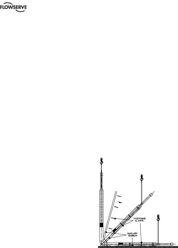
A unit that is shipped on a transport rail due to its extreme length must be lifted into the vertical position on this rail (ie an auxiliary carrier) before fitting into the well.
 Due to the danger of sagging, pump units that exceed the permissible length must be supported by an auxiliary carrier (U or H carrier) when lifted into the vertical position. This carrier may only be removed after the pump unit is hanging vertically from the crane or lifting block. (See figure 2-1.)
Figure 2-1
Submersible pumps are subjected to a thorough inspection before leaving the factory and are supplied with operating instructions for fitting, starting, care etc that conform to international safety regulations.
Immediately after receipt of the equipment it must be checked against the delivery and shipping documents for its completeness and that there has been no damage in transportation. Any shortage and or damage must be reported immediately to Flowserve and must be received in writing within one month of receipt of the equipment. Later claims cannot be accepted.
Check any crates, boxes and wrappings for any accessories or spare parts that may be packed separately with the equipment or attached to side walls of the box or equipment.
Each product has a unique serial number. Check that this number corresponds with that advised and always quote this number in correspondence as well as when ordering spare parts or further accessories.
When assessing the diameter of the unit, use the smaller size from the pump and motor. This can be found on the rating plate or the data sheet.
Page 9 of 40 |
flowserve.com |

PLEUGER STANDARD USER INSTRUCTIONS ENGLISH 71569293 01-13
Table 2-1
Rated diameter |
Permissible length |
6 in. (152 mm) |
3.3 m (10.8 ft) |
8 in. (203 mm) |
3.5 m (11.5 ft) |
|
|
10 in. (254 mm) |
4.4 m (14.4 ft) |
|
|
12 in. (305 mm) |
4.7 m (15.4 ft) |
|
|
 Under no circumstances must the power cables be used for lifting or moving the motor.
2.3.3Storing for up to four weeks
No special arrangements are required.
2.3.4Storing between one and 24 months
For storage between one and 24 months, it is recommended that the shaft of the unit be turned at intervals of approximately 8 weeks. For this it may be necessary to remove a mounted pressure housing, including the check valve. On pump units where this is not possible, the pump and motor must be separated.
2.3 Storage
 Store the pump unit vertically in a dry, well ventilated location. If it cannot be foreseen when the unit will be installed, the following instructions must be followed:
2.3.1 General remarks
 Submersible pump units need special storage conditions. For functional reasons some inner parts (eg the stator and rotor plates) cannot be produced from corrosion-resistant materials and are therefore sensitive to any type of air humidity.
All units may basically be stored either in a filled or unfilled condition; however these two types of storage require different treatment of the unit.
 All units must be stored vertically, secured appropriately in this position to prevent tipping over.
 The leads of the power cables must be protected from moisture. Ensure that the power cables and, if applicable, the signal cables are not bent during storage.
2.3.2 Requirements for the storage area
The storage area must be well ventilated.
Air humidity should be in a range of 40 to 60 %.
Temperatures:
+50 to -25 °C (+122 to -13 °F) for units with unfilled motors
+50 to 0 °C (+122 to +32 °F) for units with MX type motors (water-filled without antifreeze)
+50 to -15 °C (+122 °F to +5 °F) for units with motors originally filled by the manufacturer
For temperatures down to -15 °C, (+5 °F) see the guidelines in the instructions for filling submersible pump motors in section 0, 6.1 Antifreeze.
If needed, separate instructions should be requested from the manufacturer.
2.3.5 Storing for over 24 months
 If the pump unit is stored for more than 24 months a complete visual inspection at the Flowserve manufacturing plant is recommended. An authorised Flowserve factory representative can also carry out this inspection.
2.5 Recycling and end of product life
At the end of the service life of the product or its parts, the relevant materials and parts should be recycled or disposed of using an environmentally acceptable method and local requirements.
If the product contains substances that are harmful to the environment, these should be removed and disposed of in accordance with current regulations. This also includes the liquids and or gases that may be used in the "seal system" or other utilities.

 Make sure that hazardous substances are disposed of safely and that the correct personal protective equipment is used. The safety specifications must be in accordance with the current regulations at all times.
3 DESCRIPTION
3.1 Technical data
Each unit is individually manufactured to the special requirements of the customer. The specific technical data regarding head, delivery rate, current requirement, minimum permissible flow velocity on the external motor surfaces etc can be found in the data sheet delivered with the unit or in the order confirmation.
3.2 Delivery contents
Pump unit
These User Instructions
Technical data sheet
Page 10 of 40 |
flowserve.com |

PLEUGER STANDARD USER INSTRUCTIONS ENGLISH 71569293 01-13
3.3 General data
3.3.1 Normal operating conditions
Temperature: see data sheet
Sand content: max. 25 mg/l (0.03 oz/fl.oz)
Water velocity along motor surface: see data sheet
No impurities that could lead to deposits and blockages within the pump or to deposits on the motor surface
No water hammer
Maximum 3 minutes operation against closed slide valve
 Refer to section 7.1.2., First switching on.
Operation within prescribed voltage tolerances
Permissible operational range: 50 to 120 % of the best efficiency point (BEP)
Correctly selected and adjusted motor protection
Observation of the maximum permissible starting frequency
 If other working conditions are required please contact Flowserve for advice.
 At higher ambient temperatures and/or lower flow velocities on the external motor surfaces, or if there is risk of clogging, special measures for heat dissipation are required. This must be checked with the manufacturer by indicating the ambient conditions. In this case the suitability of the unit for its planned application must be confirmed by the manufacturer.
3.4 General description
Submersible-motor pumps are subjected to a thorough inspection before leaving the factory and are supplied with operating instructions for fitting, starting and care that conform to general safety regulations.
Standard submersible-motor pumps are used to transport cold clean water under normal operating conditions.
The Pleuger submersible-motor pump has been developed for installation in wells and as a result has a distinctive slim design. The Pleuger submersible-motor pump, because of its various features, can also be used for other applications with different design modifications.
The submersible motor pump consists of a submersible motor, a submersible pump and usually a check valve. The complete pump unit is freely suspended on the rising main which is supported at the wellhead.
Page 11 of 40
Other uses or applications must be agreed by the manufacturer.
Power cables and, if applicable, signal cables are fixed to the riser pipes by means of cable clips.
The ideal construction of a water supply system is shown in figure 3-1. Since this shows a basic arrangement, the actual layout must be adapted to local and technical conditions.
The additional listed components are recommendations for operational safety and the protection of the pump unit.
Figure 3-1: Water supply system
flowserve.com |

PLEUGER STANDARD USER INSTRUCTIONS ENGLISH 71569293 01-13
Ref. |
Description |
|
|
1a |
Submersible motor |
1b |
Submersible pump |
2 |
Check valve |
3 |
Riser pipe |
4 |
Cable clips |
5 |
Support clamp |
6 |
Elbow |
7 |
Control valve |
8 |
Delivery pipe |
9a |
Pressure vessel |
9b |
High level tank |
10 |
Terminal box for power cable |
11 |
Switchgear or switchboard |
12a |
Pressure switch |
12b |
Float switch |
13 |
System fuses |
14 |
Centering device |
15 |
Pressure gauge |
16 |
Well shaft vents |
17 |
Double orifice air valve |
18 |
Safety valve |
19 |
Check valve (optional) |
For safe operation, the following are also recommended:
20a |
Water level detector, upper |
|
20b |
Water level detector, lower |
|
|
21 |
Pressure sensor for water level measuring system |
|
22 |
Flowmeter |
Explanations and abbreviations: |
||
DB |
Well diameter |
|
ET |
Installation depth |
|
LA |
Unit length incl. check valve |
|
US |
Lower operating level = dry running protection |
|
OS |
Upper operating level (only for automatic operation |
|
Ü |
Minimum water level above pump outlet |
|
V |
To the consuming device |
|
WT |
Minimum (dynamic) water level |
|
|
(depending on NPSH) |
|
AConnection for a three-phase motor
BConnection for a single-phase motor
3.5 Submersible motor
The so-called “wet” electric motor is a water-filled three-phase AC squirrel-cage motor with a watertight winding, which is operating in water and is designed especially for direct drive of submersible pumps. The motor filling-water cools the winding and bearings as well as lubricating the thrust and radial bearings.
The submersible-motor-pump is connected to the lower end of a riser pipe and submerged in the pumped medium. The power supply is through water resistant power cables fastened to the riser pipes with cable clips.
For operation the motor must be filled with potable water. Antifreeze can be added to the potable water if there is a risk of freezing.
As the motor is hermetically sealed and equipped with a pressure/volume compensating device the motor filling remains in the motor for the duration of operation.
On motors larger than 10 in. (254 mm) an impeller fitted on the motor shaft provides an internal water circuit for better cooling.
When the unit is operating, the motor filling-water becomes warm and increases in volume. Excess water is released through a vent valve/pressure relief valve located at the top of the motor. After the unit is switched off, the filling-water cools down and the volume decreases. A breather diaphragm compensates for the lower pressure resulting from the decrease in volume. This arrangement avoids under-pressure in the motor and the ingress of pumped medium. The change of volume by varying temperatures continues over the entire lifetime of the pump unit.
Although the motor filling-water and the pumped liquid surrounding the motor will mix if there is leakage from the seals, the motor remains operative due to its water-lubricated journal bearings.
At lower installation depth the motor can, on customer request, be equipped with a header tank connected to the motor with a filling and venting pipeline instead of a pressure compensating system.
Basically, “wet” motors operate maintenance-free with the ammeter acting as a monitoring device.
The internal temperature of the motor can be monitored with one or two additional temperature sensors mounted inside the end coils of the motor winding. These sensors can trigger a high temperature warning signal or switch off the motor.
3.5.1 Stator winding
The stator winding consists of winding wire provided with special insulation.
The power cables are connected to the winding by a special watertight splice and leave the motor through stuffing boxes.
The winding and cable connections are tested at high voltage according VDE 0530 IEC60034-1 immersed in water, at twice the operating voltage plus 1 000 volts, or a minimum of 2 000 volts.
Page 12 of 40 |
flowserve.com |
 Loading...