


|
USER INSTRUCTIONS |
Limitorque PT Series |
Installation |
FCD LMENM2001-00 – 01/10 |
Operation |
|
Maintenance |
|
|
Experience In Motion

|
|
|
Limitorque PT Series Worm Gear Operator |
FCD LMENIM2001-00 – 01/10 |
|
Contents |
|
||
|
1 |
Introduction |
|
|
|
|
1.1 |
Purpose |
4 |
|
|
1.2 |
User Safety |
4 |
|
2 Inspection, Installation, and Mounting Procedures |
5 |
||
|
|
2.1 |
Initial Inspection and Storage Instructions |
6 |
|
|
2.2 |
Inspection and Recording |
6 |
|
|
2.3 |
Storage Procedure |
6 |
|
|
2.4 |
General Mounting Instructions |
7 |
|
|
2.5 |
Setting Position Limit Stops for PT 12, 14, 30, 40, 50, 75 |
8 |
|
|
2.6 |
Setting Position Limit Stops PT60 |
9 |
|
|
2.7 |
Setting Position Limit Stops for PT 65, 120, 150 |
10 |
|
|
2.8 |
Setting Position Limit Stops for PT 250, 500, 1000 |
11 |
|
3 |
Lubrication |
12 |
|
|
4 Disassembly and Reassembly Instructions |
13 |
||
|
|
4.1 |
Safety Precautions |
13 |
|
|
4.2 |
Safety Practices |
14 |
|
|
4.3 |
PT 12, 14, 30, 40 |
14 |
|
|
4.4 |
PT 50, 75 |
18 |
|
|
4.5 PT 60 |
21 |
|
|
|
4.6 |
PT 65, 120, 150 |
25 |
|
|
4.7 |
PT 250, 500, 1000 |
28 |
|
|
4.8 |
Spur Gear Attachments - PT 14, 30, 40 |
31 |
|
|
4.9 |
Spur Gear Attachments - PT 60 |
34 |
|
|
4.10 Spur Gear Attachments - PT 65, 120, 150 |
37 |
|
|
|
4.11 Spur Gear Attachments - PT 250, 500, 1000 |
39 |
|
|
5 How to Order Parts |
42 |
||
|
Figures |
|
||
|
Figure 2.1 – Typical PT Exploded View |
5 |
||
|
Figure 2.2 – Setting Position Limit Stops – PT12, 14, 30, 40, 50, 75 |
8 |
||
|
Figure 2.3 – Setting Position Limit Stops – PT60 |
9 |
||
|
Figure 2.4 – Setting Position Limit Stops – PT65, 120, 150 |
10 |
||
|
Figure 2.5 – Setting Position Limit Stops – PT250, 500, 1000 |
11 |
||
|
Figure 4.1-2 – PT12, 14, 30, 40 Disassembly & Reassembly |
16 |
||
|
Figure 4.3-5 – PT50, 75 Disassembly & Reassembly |
20 |
||
|
Figure 4.6-7 – PT60 Disassembly & Reassembly |
23 |
||
|
Figure 4.8-11 – PT65, 120, 150 Disassembly & Reassembly |
26-27 |
||
|
Figure 4.12-13 – PT250, 500, 1000 Disassembly & Reassembly |
30 |
||
|
Figure 4.14 – PT14, 30, 40 SGA Disassembly & Reassembly |
33 |
||
|
Figure 4.15-17 – PT60 SGA Disassembly & Reassembly |
35-36 |
||
2 |
Figure 4.18-20 – PT65, 120, 150 SGA Disassembly & Reassembly |
37-38 |
||
Figure 4.21-22 – PT250, 500, 1000 SGA Disassembly & Reassembly |
40-41 |
|||

|
Limitorque PT Series Worm Gear Operator FCD LMENIM2001-00 – 01/10 |
||
Tables |
|
|
|
Table 2.1 – Stem Adapter Bolt Torques |
7 |
|
|
Table 3.1 – Lubricants |
12 |
|
|
Table 4.1 – Parts List – PT12, 14, 30, 40 |
17 |
|
|
Table 4.2 – Parts List – PT50, 75 |
21 |
|
|
Table 4.3 – Parts List – PT60 |
24 |
|
|
Table 4.4 – Parts List – PT65, 120, 150 |
28 |
|
|
Table 4.5 – Parts List – PT250, 500, 1000 |
31 |
|
|
Table 4.6 |
– Parts List – Spur Gear Attachment – PT14, 30, 40 |
33 |
|
Table 4.7 |
– Parts List – Spur Gear Attachment – PT60 |
36 |
|
Table 4.8 |
– Parts List – Spur Gear Attachment – PT65, 120, 150 |
39 |
|
Table 4.9 |
– Parts List – Spur Gear Attachment – PT250, 500, 1000 |
41 |
|
3
flowserve.com

Limitorque PT Series Worm Gear Operator FCD LMENIM2001-00 – 01/10
1 Introduction
1.1 Purpose
The installation and maintenance manual (IOM) explains how to install and maintain the Flowserve Limitorque PT operator. Information on installation, disassembly, reassembly, lubrication, and spare parts is provided.
1.2 User Safety
Safety notices in this manual detail precautions the user must take to reduce the risk of personal injury and damage to the equipment. The user must read and be familiar with these instructions before attempting installation, operation, or maintenance. Failure to observe these precautions could result in serious bodily injury, damage to the equipment. voiding of the warranty, or operational difficulty.
Safety notice are presented in this manual in three forms:
cWarning: Refers to personal safety. Alerts the user to potential danger. Failure to follow warning notices could result in personal injury or death.
aCAUTION: Directs the user’s attention to general precautions that, if not followed, could result in personal injury and/or equipment damage.
NOTE: Highlights information critical to the user’s understanding of the operator’s installation and operation.
4

Limitorque PT Series Worm Gear Operator FCD LMENIM2001-00 – 01/10
2 Inspection,Installation, and
Mounting Procedures
Figure 2.1 – Typical PT Exploded View
cWarning: Do not manually operate the PT operator with devices other than the installed handwheel or wrench
nut. Using additive force devices (cheater bars, wheel wrenches, pipe wrenches, or other devices of this nature) |
5 |
on the operator handwheel or wrench or wrench nut may cause serious personal injury and/or damage to the |
|
operator or valve.
flowserve.com

Limitorque PT Series Worm Gear Operator FCD LMENIM2001-00 – 01/10
2.1 Initial Inspection and Storage Instructions
c Warning: Read this installation and maintenance manual carefully and completely before attempting to store the operator. If an electric actuator is attached to the PT manual operator, be aware of the electrical hazards. Consult the electric actuator installation and maintenance manual for guidance.
2.2 Inspection and Recording
Upon receipt of the operator, inspect the condition of the equipment, and record nameplate information.
1.Carefully remove operator from shipping carton or skid. Thoroughly examine the equipment for any physical damage that may have occurred during shipment. If damaged, immediately report the damage to the transport company.
2.A nameplate is attached to each operator with the following information:
•Operator size
•Assembly position
•Order Number
•Serial number
•Customer tagging
Record this information for future reference, i.e. ordering parts, obtaining further information.
2.3 Storage Procedure
NOTE: The following is the recommended storage procedure to retain maximum product integrity during storage. Failure to comply with recommended procedure will void the warranty.
Storage (less than 1 year)
Store operators on wooden skids to protect the machined mounting flange. Place the wooden skids containing the operators in a clean, dry, protected warehouse. If the operators must be stored outside, they must be covered in polyethylene protection with silica get crystals to absorb moisture. If an electric actuator is attached to the PT, refer to the storage procedures in its respective manual for appropriate storage procedures. Rotate input shafts every three months to mix the lubricant.
6

Limitorque PT Series Worm Gear Operator FCD LMENIM2001-00 – 01/10
2.4 General Mounting Instructions
aCAUTION: To avoid the potential for disengaging the worm gear segment, ensure that the pointer cap pointer is oriented to the mid-point of the 90º valve travel. Full stroke rotation of the quadrant should not move the pointer past the corresponding Open or Close ID marks on the housing cover.
1.Place valve in full closed position.
2.Remove the pointer cap from the PT operator. Refer to Section 4 for removal/replacement instructions for the pointer cap.
3.PT12/14/30/40/50/60/75/120/150 – Slide the splined adapter onto the valve shaft and insert the key. Splined adapters include machining for a setscrew to eliminate movement of the splined adapter on the valve shaft.
4.Confirm operator stop alignment before engaging splines. Mount operator on valve and bolt securely.
5.PT65/120/150 – Remove the splined adapter from the PT and mount the PT to the valve. Align the valve shaft with the bore and key of the splined adapter. Using either the PT or electric actuator handwheel, rotate the PT drive sleeve to align the drive sleeve’s splines with the splined adapter. Slide the splined adapter down onto the valve stem and into the drive sleeve of the PT.
NOTE: Blank splined adapters are not machines for set screws.
6.PT250/500/1000 – Stem adapters are bolted into place from the top of the PT. Remove the torque nut and align the valve drive stem with the bore and key of the torque nut. Slide the torque nut onto the valve stem. Using either the PT or electric actuator handwheel, rotate the PT drive sleeve to align the drive sleeve’s threaded holes with the torque nut’s through holes. Bolt the torque nut into position. Preload properly class 8.8 fasteners, securing torque nut as follows at installation. (Preload is not set at factory.)
Table 2.1 – Stem Adapter Bolt Torques
Unit Size |
ft-lb |
N m |
|
|
|
PT250 |
475 |
640 |
|
|
|
PT500 |
700 |
950 |
|
|
|
PT1000 |
1,200 |
1,620 |
|
|
|
Fasteners that are stainless steel or other than property class 8.8 require different preload torque than listed above. Consult factory.
7.Turn PT operator input shaft to full closed position. The stops are preset for 90º travel. Be certain of correct direction of rotation.
7
flowserve.com

Limitorque PT Series Worm Gear Operator FCD LMENIM2001-00 – 01/10
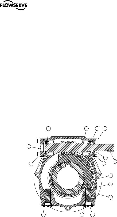
2.5 Setting Position Limit Stops - PT12, 14, 30, 40, 50, 75
Refer to Figure 2.2.
1.Remove the two Stop Screw Caps (pc# 10) (if supplied) to expose the Stop Screws (pc# 11).
2.Loosen the Stop Adjusting Nut on the Stop Screw and adjust the screw by turning it counterclockwise to back the screw away from the Worm Gear Quadrant (pc# 12)
3.Place the valve disk in the full closed position
4.Turn the Stop Screw (pc# 11) in the clockwise direction until the end of the screw contacts the Worm Gear Quadrant (pc# 12)
5.Tighten the Stop Adjusting Nut to secure the closed set position
6.Move the valve disk to the full open position
7.Follow steps 2 through 5
aCAUTION: If the valve is operated with an electric actuator/gear operator combination, and the valve is positionseated, set the actuator limit switches to trip prior to engagement of the PT Drive Sleeve/Worm Gear with the Stop Screws. Damage to the operator could result from the Drive Sleeve/Worm Gear contacting the Stop Screw under motorized operation.
Note: The stops are adjustable to +/- 5º of total travel to allow for proper positioning of the worm gear quadrant.
Figure 2.2 – Setting Position Limit Stops – PT12, 14, 30, 40, 50, 75
09 |
10 |
11 |
12 |
13 |
14 |
15 |
16 |
17 |
18 |
09B |
|
|
12A |
|
|
|
16B |
|
|
|
|
|
- |
|
|
3 |
|
|
0 |
|
|
|
- |
|
|
|
5 |
|
|
|
0 |
|
|
5 |
|
|
|
C |
|
|
|
DIVISION OF
SERIAL No:
0
01
FULLY GREASE
8 |
08 |
07 |
06 |
05 |
04 |
03 |
02 |
|
|
02B |

Limitorque PT Series Worm Gear Operator FCD LMENIM2001-00 – 01/10
2.6 Setting Position Limit Stops - PT60
Refer to Figure 2.3.
1.Loosen the Stop Adjusting Nut (pc# 8)
2.Turn the Stop Adjusting Screw (pc# 7) counterclockwise to back the screw away from the Worm Gear (pc# 19)
3.Place the valve disk in the full closed position (pointer will point to the full closed marking on the Gear Housing, pc# 2)
4.Turn the Stop Adjusting Screw in the clockwise direction until the end of the screw contacts the Worm Gear
5.Tighten the Stop Adjusting Nut to secure the closed set position
6.Move the valve disk to the full open position
7.Follow steps 1 through 5
aCAUTION: If the valve is operated with an electric actuator/gear operator combination, and the valve is position-seated, set the actuator limit switches to trip prior to engagement of the PT Worm Gear with the Stop
Screws. Damage to the operator could result from the Worm Gear contacting the Stop Screw under motorized operation.
Note: The stops are adjustable to +/- 5º of total travel to allow for proper positioning of the worm gear quadrant.
Figure 2.3 – Setting Position Limit Stops – PT60 |
|
|
|
3 |
18 |
20 |
9 |
|
|
||
2 |
|
|
|
17 |
|
|
|
6 |
|
|
|
15 |
|
|
|
12 |
|
|
21 |
|
|
|
|
11 |
|
|
|
10 |
|
|
|
8 |
|
|
19 |
|
|
|
|
7 |
|
|
4 |
|
|
|
|
|
|
|
9 |
|
|
1 |
|
flowserve.com
Limitorque PT Series Worm Gear Operator FCD LMENIM2001-00 – 01/10
2.7 Setting Position Limit Stops - PT65, 120, 150
Refer to Figure 2.4.
1.Remove the Stop Plates (pc# 9) and Stop Plate Gaskets (pc# 10) to expose the Stop Screws (pc# 7)
2.Remove the outboard Stop Screws
3.Turn the inboard Stop Screw counterclockwise to back the screw away from the Drive Sleeve/Worm Gear
4.Place the valve disk in the full closed position (pointer will point to the full closed marking on the Gear Housing)
5.Turn the Stop Screw in the clockwise direction until the end of the screw contacts the Drive Sleeve/Worm Gear
6.Install the outboard Stop Screw and tighten firmly against the inboard Stop Screw to secure the closed set position
7.Move the valve disk to the full open position
8.Follow steps 3 through 6
aCAUTION: If the valve is operated with an electric actuator/gear operator combination, and the valve is positionseated, set the actuator limit switches to trip prior to engagement of the PT Drive Sleeve/Worm Gear with the Stop Screws. Damage to the operator could result from the Drive Sleeve/Worm Gear contacting the Stop Screw under motorized operation.
Note: The stops are adjustable to +/- 5º of total travel to allow for proper positioning of the worm gear quadrant.
Figure 2.4 – Setting Position Limit Stops – PT65, 120, 150
18 |
3 |
23 |
21 |
6 |
|
|
|
19 |
|
20 |
5 |
8 |
|
||
|
|
2 |
|
|
1 |
|
|
7 |
10 |
10 |
9 |
11 |

Limitorque PT Series Worm Gear Operator FCD LMENIM2001-00 – 01/10
2.8 Setting Position Limit Stops – PT250, 500, 1000
Refer to Figure 2.5.
1.Loosen the Stop Adjusting Nut (pc# 11)
2.Turn the Stop Adjusting Screw (pc# 10) counterclockwise to back the screw away from the Drive Sleeve/Worm Gear (pc# 3)
3.Place the valve disk in the full closed position (pointer will point to the full closed marking on the Gear Housing, pc# 1)
4.Turn the Stop Adjusting Screw in the clockwise direction until the end of the screw contacts the Drive Sleeve/Worm Gear
5.Tighten the Stop Adjusting Nut to secure the closed set position
6.Move the valve disk to the full open position
7.Follow steps 1 through 5
aCAUTION: If the valve is operated with an electric actuator/gear operator combination, and the valve is position-seated, set the actuator limit switches to trip prior to engagement of the PT Worm Gear with the Stop Screws. Damage to the operator could result from the Worm Gear contacting the Stop Screw under motorized operation.
Note: The stops are adjustable to +/- 5º of total travel to allow for proper positioning of the worm gear quadrant.
Figure 2.5 – Setting Position Limit Stops – PT250, 500, 1000 |
|
|
|
|
15 |
3 |
1 |
|
|
|
|
11 |
||
|
7 |
|
12 |
|
9 |
|
|
|
|
|
|
|
|
|
8 |
|
|
|
|
6 |
|
|
|
10 |
|
|
|
|
|
2 |
|
|
|
|
6 |
|
|
|
|
21 |
|
|
|
2X 2.29 |
|
|
|
|
|
17 |
|
|
|
ASSEMBLE STOPS |
|
|
|
TO THIS DIMENSION |
|
|
|
|
|
|
45 |
|
|
|
|
|
Wormshaft & Stops |
22 |
|
11 |
|
|
|
||
|
Scale 1 : 3 |
|
|
|
15 |
25 |
|
|
|
|
|
|
|
|
flowserve.com

Limitorque PT Series Worm Gear Operator FCD LMENIM2001-00 – 01/10
3 Lubrication
Flowserve Limitorque PT operators are shipped with the following lubricants:
Table 3.1 – Lubricants
Product |
Lubricant |
Soap Base |
Temperature Range |
|
|
|
|
PT 12, 14, 30, 40, 50, 75 |
Premium MC 2092SW |
Calcium |
-65ºF to 225ºF (-54ºC to 107ºC) |
|
|
|
|
PT 60 |
Esso Unirex EP-2 |
Lithium |
-22ºF to 176ºF (-30ºC to 80ºC) |
|
|
|
|
PT 65, 120 through 1000 |
Conoco Dynalife-L-EPO |
Lithium |
0ºF to 225ºF (-18ºC to 107ºC) |
|
|
|
|
NOTE: The lubricant should be checked every 18 months for manual operators.
aCAUTION: Do not add a different lubricant to a Flowserve Limitorque operator unless it is of the same soap base as the existing lubricant, or you have received the approval of lubricant manufacturer.
Quantity
Limitorque operators are built to operate on the partial immersion principle. The primary concern regarding the amount of lubricant is whether the “worm” is totally immersed in grease. This can be verified by the use of one or more of the
“fill” and “drain” plugs provided on the operator housing in most sizes.
Quality
When removing a “fill” or “drain” plug to inspect the lubricant level, remove a small amount and ensure that it is clean and free of any contaminant including water. Should dirt, water, or other foreign matter be found, the operators should be flushed with a commercial degreaser/cleaner like Exxon VARSOL #1 or #3, which is non-corrosive and does not affect seal materials such as Buna-N or Viton. Repack operator with fresh lubricant.
Consistency
The main gear box lubricant should be slightly fluid, approximating a standard NLGI-0 grade consistency or less.
Alternate lubricants may be used in place of the standard lubricants supplied by Flowserve provided they are of a formulation similar to those listed above for the respective product.
12

Limitorque PT Series Worm Gear Operator FCD LMENIM2001-00 – 01/10
4 Disassembly and
Reassembly Instructions
4.1 Safety Precautions
cWarning: Read this Installation, Operation and Maintenance Manual carefully and completely before attempting to install, operate, or troubleshoot the Limitorque operator.
cWarning: Potential HIGH PRESSURE vessel — be aware of high-pressure hazards associated with the attached valve or other actuated device when installing or performing maintenance on the operator. Do not remove the operator mounting bolts from the valve or actuated device unless the valve or device stem is secured or there is no pressure in the line.
cWarning: For maintenance and/or disassembly of the operator while installed on the valve, ensure that the operator is not under thrust or torque load. If the valve must be left in service, the valve stem must be locked in such a way as to prevent any movement of the valve stem.
cWarning: Do not manually operate the operator with devices other than the installed handwheel. Using force beyond the ratings of the operator and/or using additive force devices such as cheater bars, wheel wrenches, pipe wrenches, or other devices on the operator handwheel may cause serious personal injury and/or damage to the operator and valve.
cWarning: Do not exceed any design limitations or make modifications to this equipment without first consulting Limitorque.
cWarning: Use of this product must be suspended any time it fails to operate properly.
aCAUTION: If a motor actuator is driving the manual operator, do not operate the valve under motor operation without first checking and setting the limit switch and checking for correct motor rotation.
aCAUTION: Do not use replacement parts that are not genuine Flowserve Limitorque parts, as serious personal injury and/or damage to the operator and valve may result.
13
flowserve.com

Limitorque PT Series Worm Gear Operator FCD LMENIM2001-00 – 01/10
4.2 Safety Practices
The following check points should be performed to maintain safe operation of the PT gear operator:
•Set up a periodic operating schedule on infrequently used valves.
•Ensure that the limit and/or torque switches on any electric actuator fitted to the PT worm gear operator are correctly and appropriately adjusted.
4.3 PT12, 14, 30, 40
Refer to Figures 4.1, 4.2 and Table 4.1.
1.Remove the Key (pc# 18) from the Worm Shaft (pc# 2) assembly.
2.Remove the plastic Indicator Cap (pc# 19) by applying equal pressure underneath the cap, on opposite sides of the cap, and prying upward.
Note: The metal Indicator Cap is removed by removing the two screws that attach the Indicator Cap to the Quadrant.
3.Remove the Flange Cover Hex Head Screws (pc# 9)
4.Turn the operator onto its side and tap on the Quadrant (pc# 12) and flange of the Cover (pc# 1) to separate the Cover, Worm Shaft (pc# 2) assembly, and Quadrant from the Gearcase (pc# 21).
Caution: Use a soft-headed mallet to prevent damage to the Quadrant bore and keyways.
Caution: Care should be taken to prevent the Quadrant and Worm Shaft assembly from completely disengaging from the Gearcase.
Note: The Flange Cover will not separate from the Gearcase without adequate force to overcome and clear the dowel pin connections between the Flange Cover and Gearcase.
5.Return the operator to the upright position.
6.With the Quadrant free from the base of the Gearcase, lift the Cover, Quadrant, and Worm Shaft assembly from the Gearcase and slide the Worm Shaft assembly away from the Quadrant.
7.Remove the Quadrant from the Gearcase.
8.Slide the Worm Shaft assembly out of the Flange Cover.
Note: If additional disassembly is required, please follow the steps below:
9. Remove the Snap Ring (pc# 17) and tap out the Input Bearing (pc# 16) from the Cover.
Note: The Smalley Retaining Ring (pc# 3) and Protection Sleeve (pc# 15) can be removed if required. Remove the Protection Sleeve by tapping it out of the Flange Cover.
10.Remove Thrust Washers (pc# 7), Thrust Bearings (pc# 6), Worm Shaft Bearings (pc# 5), and Oil Seal (pc# 4) as required.
14
 Loading...