


USER INSTRUCTIONS
Worcester Controls
Pulsair III Digital
Electronic Positioner
FCD WCAIM2056-00 – 08/04 (Replaces IOM-19990)
Installation
Operation
Maintenance
Experience In Motion

Worcester Controls Pulsair III Digital Electronic Positioner FCD WCAIM2056-00 - 08/04
Contents
Worcester Controls Pulsair III Digital Electronic Positioner FCD WCAIM2056-00 - 08/04
1 Introduction 4
Safety Instruction 4
2 Storage 5
General 5
Storage Indoors 5
Storage Outdoors or for a Longer Period 6
Storage in a Warm Place 6
3 Design 7
4 Variants 8
Pulsair III 270° (W) 8
Pulsair III Explosion-Proof (Z) 8
Pulsair III Intrinsically Safe 8
Pulsair III Remote Mounted 8
5 Function 9
Double-Action Function 9
Single-Action Function 9
6 Installation 10
Tubing 10
Air Supply Requirements 10
Mounting 11
Connections 12
Air 12
Electrical Connection 12
Dimensions 12
Single-Action Positioner (Direct Function) 13
Double-Action Positioner (Direct Function) 14
Electrical Connections 14
7 Control 16
Menu and Pushbuttons 16
Other Functions 16
Menu Indicator 17
Menus 17
Changing Parameter Values 18
Basic Menu: Calibrate 19
First Start 19
Calibration Error Messages 19
Basic Menu: Read 22
Basic Menu: Man/Aut 23
Basic Menu: Shift Menu 23
Full Menu: Protection 24
Full Menu: Status 25
Full Menu: Setup 26
Full Menu: Tuning 32
Full Menu: Alarms 34
Full Menu: Fact Set 38
8 Maintenance/Service 40
Disassembling Pulsair III W 40
Silencer 44
Spindle Adapter 44
Potentiometer 45
Transmitter Boards 46
Disassembling the Worcester Pulsair III Z 51
Filter Change, Pulsair III W and Z 52
Converting for Remote Control 52
9 Troubleshooting 54
10 Technical Data 55
11 Spare Parts 58
2
fl owserve.com
3

Worcester Controls Pulsair III Digital Electronic Positioner FCD WCAIM2056-00 - 08/04
1 Introduction
The PULSAIR III is a digital positioner designed primarily for controlling modulation
valves.
Worcester Controls Pulsair III Digital Electronic Positioner FCD WCAIM2056-00 - 08/04
Warning:
a
• The valve package moves when in operation and can cause personal injury or damage
if handled incorrectly.
The positioner can be used with single- or double-action actuators with either rotary or
linear movement.
The PULSAIR III can be equipped with modules for feedback, limit switches, and a
pressure gauge block.
The modules can be factory-assembled before delivery or fi tted later.
The modules for feedback and limit switches can contain 4-20 mA feedback and one of
the following functions:
• Two mechanical switches
• Two reed switches
• Two inductive sensors
Safety notices are presented in this manual in three forms:
Warning: Refers to personal safety. Alerts the user to potential danger. Failure to
a
follow warning notices could result in personal injury or death.
Caution: Directs the user’s attention to general precautions that, if not followed,
c
could result in personal injury and/or equipment damage.
NOTE: Highlights information critical to the user’s understanding of the actuator’s installation and operation.
• If the input signal fails or is turned off, the valve moves quickly to its end position.
• If the compressed air supply fails or is turned off, fast movements can occur.
• The valve is not controlled by the input signals when in the “Out of service” mode. It
will open/close in the event of a leak.
• If a high value is set for Cut off, fast movements can occur.
• If the valve is controlled in the Manual mode, the valve can move quickly.
• Incorrect settings can cause self-oscillation, which can lead to damage.
Important:
• Always turn off the compressed air supply before removing or disconnecting the air
supply or the integral fi lter. Remove or disconnect with care because C- is still under
pressure even after the air supply is turned off.
• Always work in an ESD protected area when servicing the PCBs. Make sure the input
signal is switched off.
• The air supply must be free from moisture, water, oil and particles.
2 Storage
Safety Instruction
Read the safety instructions in this manual carefully before using the product. The
installation, operation, and maintenance of the product must be done by staff with the
necessary training and experience. If any questions arise during installation, contact the
supplier/sales offi ce before continuing work.
4
General
The PULSAIR III positioner is a precision instrument. Therefore, it is essential that it is
handled and stored in the correct way. Always follow the instructions below!
NOTE: As soon as the positioner is connected and started, an internal air leakage will
provide protection against corrosion and prevent the ingress of moisture. For this
reason, the air supply pressure should always be kept on.
5
fl owserve.com

Worcester Controls Pulsair III Digital Electronic Positioner FCD WCAIM2056-00 - 08/04
Worcester Controls Pulsair III Digital Electronic Positioner FCD WCAIM2056-00 - 08/04
Storage Indoors
Store the positioner in its original packaging. The storage environment must be clean,
dry, and cool 60-80°F (15-26°C).
Storage Outdoors or for a Longer Period
If the positioner must be stored outdoors, it is important that all cover screws are
tightened and that all connections are properly sealed. The unit should be packed with a
desiccant (silica gel) in a plastic bag or similar, covered with plastic, and not exposed to
sunlight, rain, or snow.
This is also applicable for long-term storage (more than 1 month) and for long transport
by sea.
Storage in a Warm Place
When the positioner is stored in a warm place with a high relative humidity and is subjected to daily temperature variations, the air inside the unit will expand and contract.
This means that air from outside the unit may be drawn into the positioner. Depending
on the temperature variations, relative humidity, and other factors, condensation and
corrosion can occur inside the unit, which in turn can give rise to functional disorders or
a failure.
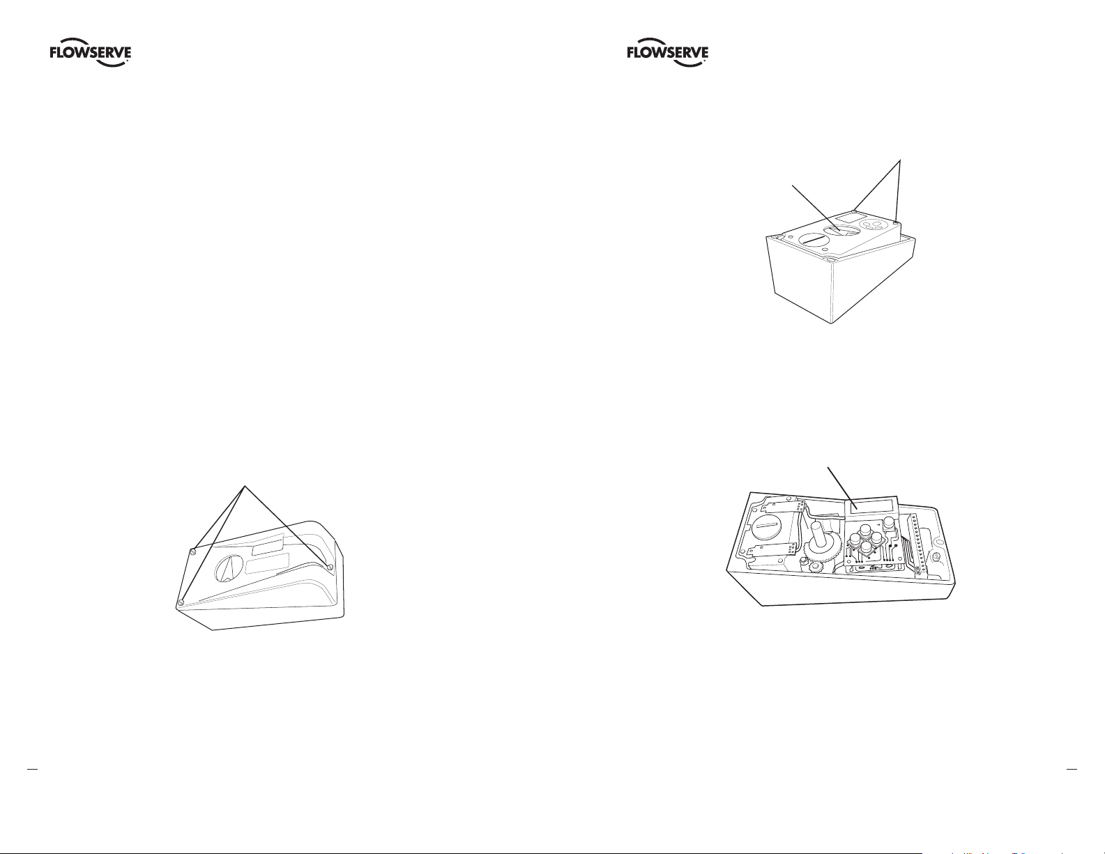
3 Design
The PULSAIR III positioner contains:
• electronic board with microprocessor, HART modem, display etc.
• pneumatic valve block
• positional feedback with potentiometer
• sealed compartment for electrical connections.
The pushbuttons and display are accessible underneath the aluminum cover, which is
sealed with an O-ring.
The fi gure shows the PULSAIR III with the cover removed.
Display, control
Filter
Adjusting screws,
damping
pushbuttons
Terminal block
Valve
block
6
Potentiometer
Processor and
motherboard
7
fl owserve.com

Worcester Controls Pulsair III Digital Electronic Positioner FCD WCAIM2056-00 - 08/04
Worcester Controls Pulsair III Digital Electronic Positioner FCD WCAIM2056-00 - 08/04
4 Variants
Pulsair III 270° (W)
A Pulsair III for up to 270° extended travel
range is available. It features all benefi ts and
options similar to the standard Pulsair III.
Communication with HART is possible.
Pulsair III Intrinsically Safe
The Pulsair III is available in an intrinsically
safe version for installation in hazardous
areas. It features the same easy-to-use user
interface for local confi guration as the Pulsair
III. Communication with HART is possible. It
features all benefi ts and options similar to the
Standard Pulsair III positioner: gauge block,
local graphic LCD display, feedback option, etc.
Pulsair III Explosion-Proof (Z)
The Pulsair III digital positioner is available
in an explosion-proof enclosure. It features
the same easy-to-use user interface for local
confi guration as the Pulsiar III. Communication
with HART is possible.
Further features are gauge ports and local
graphic LCD display.
Pulsair III Remote Mounted
The Pulsair III with remote mount is now
available. This version is suitable for
installations in severe applications, e.g.
vibration, high or low temperature, corrosive
environment, diffi cult to access installations,
etc. A fl at or dome-style indicator can be fi tted
on the feedback box installed on the actuator.
8
The maximum recommended distance between
the Pulsair III and remote unit is 16 ft. (5m).
Standard Housing
Weatherproof (W) and
Intrinsically Safe
“Z” Housing
Remote Mount
Control signal 4-20 mA
Potentiometer
Piezo–valve 2
D
Actuator
C
E
➾
Venting
C– C+
F
V enting
B
G
H
Signal converter
and microprocessor
Piezo–valve 1
Diaphragm
17.4 psig (1.2 bar)
Pressure
regulator
Replaceable
Filter
Air supply
30-105 psig
(2-7 bar)
A
5 Function
Double-Action Function
The control signal and the feedback potentiometer position are converted to digital
signals that are processed with a PID algorithm in the microprocessor. This provides
control signals to the two piezo-valves.
The two piezo-valves are closed in the schematic diagram above and have no effect on
the valves A and D. Air from the pressure regulator is lead through the open valve A
to the valve B, which opens. The supply pressure can now pass through valve B to the
actuator via H. The actuator then moves in the direction of the arrow. At the same time,
air from valve A keeps valve C open and allows venting of the actuator.
When both the piezo-valves open, valve A closes but valve D opens and controls valves
E and F to that the actuator moves in a direction opposite to the arrow. When only piezovalve 1 is open, the actuator is stationary.
Single-Action Function
Valve B is used for the supply air and valve F for venting.
9
fl owserve.com

Worcester Controls Pulsair III Digital Electronic Positioner FCD WCAIM2056-00 - 08/04
Worcester Controls Pulsair III Digital Electronic Positioner FCD WCAIM2056-00 - 08/04
6 Installation
Tubing
Use tubes with an inner diameter of ¼ " (6 mm) minimum.
Air Supply Requirements
For the maximum air supply pressure, see section 10, Technical Data.
The air supply must be free from moisture, water, oil, and particles.
The air must come from a refrigeration-dried supply or be treated in such a way that its
dew point is at least 18°F (10°C) below the lowest expected ambient temperature. If air
is now used, the supply medium must be a noncorrosive and non-fl ammable gas.
To ensure a stable and problem-free air supply, we recommend the installation of a
fi lter/pressure regulator <30 microns as close to the positioner as possible.
Before the air supply is connected to the positioner, open the hose freely for 2 to 3
minutes to allow any contamination to be blown out.
Direct the air jet into a large paper bag to trap any water, oil, or other foreign materials. If
contamination is detected, the air supply should be thoroughly cleaned before connecting to the positioner.
Warning: Do not direct the open air jet towards people or objects because it
a
may cause personal injury or damage.
Poor air supplies are the main source of problems in pneumatic and
electro-pneumatic systems.
Mounting
NOTE: If the positioner is installed in a hazardous environment, it must be of a type
approved for this purpose.
The PULSAIR III W positioner has an ISO F05 footprint, A. The holes are used to attach it
to the mounting bracket B, which is suitable for most types of linear actuator.
The spindle adapter C can be changed to suit the actuator in question.
C
Remove the existing adapter using two screwdrivers. Check that the spring ring on the
new spindle is undamaged and fi ts the new adapter before installing.
It is important that the positioner’s spindle and the arms that transfer the actuator
movements are correctly mounted. Any tension between these parts can cause incorrect
operation and abnormal wear.
Assembly Examples
A
B
Linear Movement
Rotary Movement
B
10
C
11
fl owserve.com

Worcester Controls Pulsair III Digital Electronic Positioner FCD WCAIM2056-00 - 08/04
Worcester Controls Pulsair III Digital Electronic Positioner FCD WCAIM2056-00 - 08/04
The PULSAIR III Z positioner has an ISO F05 footprint, A. The holes are used to attach it
to the mounting bracket B, which is suitable for most types of linear actuators.
The spindle adapter C can be changed to suit the actuator in question, as previously
explained in this section.
For data for air and electrical connections, see Technical Data section.
A
B
C
Connections
Air
Port S Supply air
Port C+ Connection to actuator
Port C- Connection to actuator (only for
double-action)
Must be plugged
when converting
to single-action
function.
Electrical Connection
See Electrical Connections section.
Dimensions
Air connections: ¼ " NPT or G ¼ "
Electrical connection: ½ " NPT or M20 x 1.5
Loctite 577 or equivalent is recommended
as a sealant.
Single-Action Positioner (Direct Function)
Actuator with Fail/Close Spring
When the control signal increases, the pressure C+ to the actuator is increased. The
valve stem moves upward and rotates the positioner spindle counterclockwise. When
the control signal drops to zero, C+ is vented and the valve closes.
C
–
S
C+
C
–
S
C+
Actuator with Fail/Open Spring
When the control signal increases, the pressure C+ to the actuator is decreased. The
springs press the valve stem upward and the positioner spindle rotates counterclockwise. When the control signal drops to zero, C+ is vented and the valve opens.
For data for air and electrical connections,
C– S C+
12
see Technical Data section.
13
fl owserve.com

Worcester Controls Pulsair III Digital Electronic Positioner FCD WCAIM2056-00 - 08/04
Worcester Controls Pulsair III Digital Electronic Positioner FCD WCAIM2056-00 - 08/04
Double-Action Positioner (Direct Function)
Double-Action Actuator
When the control signal increases, the pressure C+ to the actuator is increased. The
valve stem is pressed upward and rotates the positioner spindle counterclockwise.
When the control signal is reduced, the pressure C- to the actuator increases and the
valve stem is pressed downward. If the control signal disappears, the pressure goes to
C-, C+ vents, and the valve closes.
C
–
S
C+
Electrical Connections
The diagrams on the next page show the terminal blocks in the Pulsair III W and Z.
Remote Unit
The remote unit shall be connected between terminals 3, 4 and 5 in the Pulsair III and 3,
4 and 5 in the remote unit. Use a shielded cable and ground it in the Pulsair III only. The
maximum recommended distance between the Pulsair III and the remote unit is 16 ft.,
5 in. (5 m).
Pulsair III W
1 4-20 mA + input signal
2 4-20 mA – input signal
3 Switch 1 NO
4 Switch 1 NC
5 Switch 1 COM
6 Switch 2 NO
7 Switch 2 NC
8 Switch 2 COM
9 AUX input 4-20 mA +
10 AUX input 4-20 mA –
11 4-20 mA + Feedback
12 4-20 mA – Feedback
13 Alarm output +
14 Alarm output –
Pulsair III Z
HART –
connection
1 2 3 4 5 6 7 8 9 10 11 12 13 14
+ – + – + – + –
Option
Shielded cables,
grounded in the
Pulsair III unit
HART
Connection
Connecting a
remote unit
123456
+ –
345
Remote
unit
Shielded cables,
grounded on the
Pulsair III unit
3
4
5
Remote
Unit
Note: When converting a Pulsair III W or Z for use with a remote unit, some changes
have to be done inside the positioner, see section 8.
Warning: In a hazardous environment where there is a risk of explosion,
a
electrical connections must comply with the relevant regulations.
Terminal Blocks
The terminal blocks in the illustrations at right are accessible when the terminal cover is
removed, see Section 8 for disassembly instructions.
14
Warning: In a hazardous environment where there is a risk of explosion,
a
electrical connections must comply with the relevant regulations.
1 4-20 mA + input signal
2 4-20 mA – input signal
3 Switch 1 NO (Remote unit)
4 Switch 1 NC (Remote unit)
5 Switch 1 COM (Remote unit)
9 AUX input 4-20 mA +
10 AUX input 4-20 mA –
11 4-20 mA +
12 4-20 mA –
13 Alarm output +
14 Alarm output –
Optional
15
fl owserve.com

Worcester Controls Pulsair III Digital Electronic Positioner FCD WCAIM2056-00 - 08/04
Worcester Controls Pulsair III Digital Electronic Positioner FCD WCAIM2056-00 - 08/04
7 Control
Menu and Pushbuttons
The positioner is controlled using the fi ve pushbuttons and the display, which are accessible when the aluminium cover is removed.
For normal functioning, the display shows the current value. Press the ESC button for
two seconds to display the main menu.
Use the up and down pushbuttons to browse through the main menu and the submenus.
The main menu is divided up into a basic menu and a full menu, see the fl owchart in the
section, “The Menu System.”
OUT OF
SERVICE
MANUAL
BASIC MENU
MAN/AUTO
UNPROTECTED
ESC FUNC
OK
MANUAL: The positioner can be adjusted manually using the pushbuttons. See Man/
Auto section.
UNPROTECTED: Most of the parameters can be changed when the positioner is in the
“Unprotected” position. However, critical parameters are locked when the positioner is in
the “In service” position.
Menu Indicator
There are indicators at both sides of the display window and they indicate as follows:
• Flashing in position Out of service
• Flashing in position Manual
• Displayed in position Unprotected
The indicators on the right-hand side show the position in the current menu.
Flashing in position Out of Service
FULL MENU
MAN/AUTO
Flashing in position Manual
FULL MENU
CALIBRATE
Other Functions
ESC: Exit the menu without making any changes (as long as any changes have not been
confi rmed with OK).
FUNC: To select functions and change parameters.
OK: To confi rm selection or change of parameters.
MENU INDICATOR: Displays the position of the current menu row in the menu.
IN SERVICE: The positioner is following the input signal. This is the normal status when
the positioner is working.
16
OUT OF SERVICE: The positioner is not following the input signal. Critical parameters
can be changed.
Displayed in position Unprotected
FULL MENU
SHIFT MENU
Menus
To display the menu you can select:
• Basic menu, which means you can browse through four different steps
• Full menu, which comprises ten steps. Use the Shift Menu to browse through the
steps.
Full Menu can be locked out using a passcode.
The main menus and submenus are shown on the subsequent pages.
fl owserve.com
17

Worcester Controls Pulsair III Digital Electronic Positioner FCD WCAIM2056-00 - 08/04
Worcester Controls Pulsair III Digital Electronic Positioner FCD WCAIM2056-00 - 08/04
Changing Parameter Values
Change by pressing the left and right arrows until the desired fi gure is fl ashing.
Press the up and down arrows to step to
the desired fi gure. Confi rm by pressing OK.
A change can be undone by pressing the
ESC button, which returns you to the previous menu.
BASIC MENU
READ
BASIC MENU
MAN/AUTO
BASIC MENU
CALIBRATE
BASIC MENU
SHIFT MENU
FULL MENU
READ
FULL MENU
MAN/AUTO
FULL MENU
CALIBRATE
FULL MENU
SHIFT MENU
FULL MENU
PROTECTION
FULL MENU
STATUS
FULL MENU
SETUP
FULL MENU
TUNING
Basic Menu: Calibrate
BASIC MENU
CALIBRATE
First Start
Calibrate in the basic menu is displayed automatically the fi rst time the positioner is connected, and can be selected from the basic/main menu at any later time.
A complete calibration takes about three minutes and includes end limit calibration,
auto-tuning, leak test, and a check on the speed of movement. Start the automatic calibration by selecting Auto-Cal and then answer the questions on the display by pressing
OK or the respective arrow. The menu is described later in this section.
Calibration Error Messages
If a fault occurs during the calibration, one of the following error messages will be
displayed:
Invalid movement/press ESC to abort
No movement because the air is incorrectly connected, for example. After the fault is
corrected, the calibration sequence must be restarted.
Pot unaligned/press ESC to abort
The potentiometer has been set to an illegal value. The potentiometer is aligned using
the Calibrate - Expert cal - pot Menu. The calibration sequence must be restarted after
the fault is corrected.
FULL MENU
ALARMS
FULL MENU
FACT SET
18
An air leak has been detected. The calibration sequence should be restarted after the
fault is corrected.
Increase C- damper/ESC = abort OK to retry
Increase C+ damper/ESC = abort OK to retry
Clockwise Increased damping/Less flow
CCW Decreased damping/More flow
3 revs CCW Maximum flow
C+
(C–)
NOTE: Too much increased damping (low flow)
might cause irregular actuator function.
fl owserve.com
19
Air leak detected/ESC = abort OK = go on

Worcester Controls Pulsair III Digital Electronic Positioner FCD WCAIM2056-00 - 08/04
Worcester Controls Pulsair III Digital Electronic Positioner FCD WCAIM2056-00 - 08/04
Speed of movement is too fast. Adjust with the damper screws. Press OK. Repeat the
adjustment and press OK until the speed is correct. If there is an abort, the calibration
sequence must be restarted.
The contents of the menu are shown on subsequent pages. The various menu texts are
described below.
Auto-Cal Auto-tuning and calibration of end positions
Start tune Starts the tuning. Questions/commands are displayed during calibra-
tion. Select the type of movement, function, etc. with the down arrow and confi rm
the OK as shown in the chart on the next page.
Lose prev value? OK? A warning that the value set previously will be lost (not
during the fi rst auto-tuning).
Actuator? Rotating Select for rotating actuator.
Actuator? Linear Select for linear actuator.
Actuator single act Select for single-acting.
Actuator double act Select for double-acting.
Direction? direct Select for direct function.
Direction? reverse Select for reverse function.
In service? Press OK Calibration fi nished. Press OK to start positioner function-
ing. (If ESC is pressed, the positioner assumes the “Out of service” position but the
calibration is retained).
TravelCal Calibration of end position
Start cal Start end position calibration
Lose prev value? OK? A warning that the previously set value will be lost. Confi rm
with OK. The calibration sequence starts.
In service? Press OK Calibration fi nished, Press OK to start positioner functioning. (If ESC is pressed, the positioner assumes the “Out of service” position but the
calibration is retained).
Perform Setting gain
Normal 100% gain
Perform 50%, 25%, 12%, L, M, S Possibility to select a lower gain in steps
L, M, S Preset values for L, M, S actuators
20
Factory set Resets all set values and enters Factory Mode. Should only be used by
authorized staff.
Note: Original P.I.D. will always be shown in display.
CALIBRATE
AutoCal
CALIBRATE
TravelCal
CALIBRATE
Perform
CALIBRATE
ExpertCal
AutoCal
Start tune
TravelCal
Start cal
OK
LOSE PREV
VALUE? OK?
OK
Calibration
in progress
IN SERVICE?
Press OK
OK
Set point LO: Use the calibrator set to 4 mA (or set another
value on the display). Press OK.
Set point HI: Use a calibrator of 20 mA (or set another value
on the display). Pess OK. Pressure read out only possible on
Pulsair III with built-in pressure sensor.
Pressure LO: Use a supply of 30 psi (2 bar) (or set another
value on the display). Press OK.
Pressure HI: Use a supply of 105 psi (7 bar) (or set another
value on the display). Press OK.
Temp: Calibrate using a known temperature.
Aux input LO: Use the calibrator and a power supply of 4 mA
(or set another value on the display). Press OK.
Aux input HI: Use a supply of 20 mA (or set another value on
the display). Press OK.
Pot: Potentiometer setting, if its position relative to the gear
segment has been changed. See Section 8.
Full reset: Resets all the set values.
All of these values are set at the factory before delivery and
should not normally be changed.
OK
LOSE PREV
VALUE? OK?
Actuator?
rotating
Actuator?
linear
OK
OK
OK
Actuator
single act
Actuator
single act
Direction?
direct
Direction?
reverse
OK
Calibration
in progress
IN SERVICE?
Press OK
OK
Perform
normal
Perform
50%
25%
12%
L
M
S
Perform
Factory set
OK
OK
OK
OK
OK
OK
21
fl owserve.com

Worcester Controls Pulsair III Digital Electronic Positioner FCD WCAIM2056-00 - 08/04
Worcester Controls Pulsair III Digital Electronic Positioner FCD WCAIM2056-00 - 08/04
Basic Menu: Read
The menu contents are shown in the
fi gures on the right and the steps are
described below:
BASIC MENU
READ
Current values can be read using the Read
Menu and some values can be reset.
Pos Shows current position
Set&pos Set point and position
Set&dev Set point and deviation
Temp Shows current temperature
Aux Shows aux input signal value.
External pot or similar.
Statistics
n cycles Shows number of
movements (turns)
Acc travel Shows accumulated
movement
READ
pos
READ
set&pos
READ
set&dev
READ
temp
READ
aux
READ
Statistics
READ
Alarms
Statistics
n cycles
Statistics
acc travel
Statistics
mean dev
Statistics
runtime
Statistics
extr. temp
Statistics
histogram
Statistics
Reset stat
Reset stat
yes
Reset stat
no
Basic Menu: Man/Aut
The Man/Auto menu is used to change between manual and automatic modes.
BASIC MENU
MAN/AUTO
The menu contents are shown in the fi gures below and the various texts are described
below:
AUT, OK = MAN Positioner in automatic mode
MAN, OK = AUT Positioner in manual mode
In the MAN mode, the value of POS can be changed using the up and down arrows. The
pushbuttons increase/decrease the value in steps. The value can also be changed in the
same way as for the other parameter values, as previously described.
Other Functions
C+ can be fully opened by fi rst pressing the up arrow and then immediately OK simultaneously.
C- can be fully opened by pressing the down arrow and OK simultaneously.
C+ and C- can be fully opened for blowing clean by pressing the up and down arrows
and OK simultaneously.
When changing between MAN and AUT mode, the OK button must be depressed for
three seconds.
mean dev Shows accumulated
deviation in %
runtime Shows accumulated
runtime since last reset
extr temp Shows extreme min and
max temperature
Histogram Shows position and time
22
for PV
Alarms Displays tripped alarms
AUT, OK=MAN
SET=12.3%
OK
MAN, OK=AUT
POS=12.3%
Basic Menu: Shift Menu
The Shift Menu is used to choose between the basic menu and the full menu.
BASIC MENU
SHIFT MENU
23
fl owserve.com

Worcester Controls Pulsair III Digital Electronic Positioner FCD WCAIM2056-00 - 08/04
Worcester Controls Pulsair III Digital Electronic Positioner FCD WCAIM2056-00 - 08/04
The menu contents are shown in the fi gures below and the various steps are described
below:
No Full menu selected.
Yes Basic menu selected.
Full menu
no
Full menu
yes
OK
OK
Full Menu can be locked with a passcode, see the SETUP Menu section.
Full Menu: Protection
The Protection menu is used to protect all essential settings.
FULL MENU
PROTECTION
Full Menu: Status
The Status Menu is used to select whether or not the positioner is in service.
FULL MENU
STATUS
The menu contents are shown in the fi gures below and the various texts are described
below:
o o service Not in service. Flashing indicator in upper left-hand corner of display.
in service Positioner in service. Critical parameters cannot be changed.
STATUS
o o service
STATUS
in service
OK
OK
The menu contents are shown in the fi gures below and the various steps are described
below:
No Entered values are not write-protected. “Unprotected” is displayed in the
lower left-hand corner.
Yes Entered values are write protected. Passcode needed for change to No (Ap-
plicable when a passcode has been set up in SETUP menu).
PROTECTION
no
PROTECTION
yes
24
OK
OK
When changing between Yes and No mode, the OK button must be depressed for three
seconds.
When changing between In service and Out of service, the OK button must be depressed
for three seconds.
25
fl owserve.com

Worcester Controls Pulsair III Digital Electronic Positioner FCD WCAIM2056-00 - 08/04
Worcester Controls Pulsair III Digital Electronic Positioner FCD WCAIM2056-00 - 08/04
Full Menu: Setup
The Setup Menu is used for various settings.
FULL MENU
SETUP
The menu contents are shown in the chart on subsequent pages and the various texts
are described below:
Actuator Type of Actuator
Rotating Rotating actuator
Linear Linear actuator
Size of Actuator Time Out
Small 10 s
Medium 25 s
Large 60 s
Texas 180 s
Character
Curves that show position as a function of input signal.
Linear See diagram
Equal % See diagram
Quick open See diagram
Sqr root See diagram
Custom Create own curve.
Cust chr
# of point Specify number of points (3, 5, 9, 17, or 33)
Cust curve Enter values on X and Y axes.
y
Qo
Sqr
Lin
Eq%
Movement
Lever Only for linear actuator.
Lever stroke Stroke length to achieve correct display
Level cal Calibration of positions to achieve correct display
Direction
Direct Direct function (signal increase opens). Indicator/spindle rotates
counterclockwise.
Reverse Reverse function
26
x
Signal
Curr range
0% = 4.0 mA
100% = 20.0 mA Possibility of selecting which input signal values will correspond
to 0% and 100% movement respectively. Examples of settings:
• 4 mA = 0%
• 12 mA = 100%
• 12 mA = 0%
• 20 mA = 100%
fl owserve.com
27

SETUP
Actuator
Worcester Controls Pulsair III Digital Electronic Positioner FCD WCAIM2056-00 - 08/04
Actuator
type
Typ e
linear
OK
Worcester Controls Pulsair III Digital Electronic Positioner FCD WCAIM2056-00 - 08/04
TRVL range Setting end positions
0% = 0.0% Select Out of Service. Set percentage value for desired end position
(e.g. 3%).
Displayed
only when
actuator
linear is
selected
SETUP
Lever
SETUP
Direction
SETUP
Character
SETUP
Cust chr
SETUP
curr range
Actuator
function
Actuator
size
Lever
Stroke
Lever
Lever Cal
Direction
direct
Direction
reverse
Cust chr
# of point
Cust chr
Cust curve
Curr range
0%=4.0 mA
OK
OK
See text See text
OK
Function
single act
Function
Double act
Stroke
LEN=XX,Xmm
Character
linear
Character
equal %
Character
quick open
Character
custom
OK
OK
OK
OK
OK
OK
OK
Typ e
rotating
Size
Medium
Size
Small
Size
Large
Size
Texas size
Set lever
at max ...
Set lever
at center ...
Set lever
at min ...
Set lever
at center ...
Lever cal
Done
OK
Set 0% Select In Service. Connect calibrator. Move forward to desired end posi-
tion (0%) and press OK.
100% = 100.0% Select Out of Service. Set percentage value for desired end
position (e.g. 100%).
Set 100% Select In Service. Connect calibrator. Move forward to desired end posi-
OK
tion (100%) and press OK.
TRVL ctrl Behavior at set end position
OK
Set low Choose between Free (go to mechanical stop), Limit (stop at set end posi-
tion), and Cut off (go directly to mechanical stop at set end position).
OK
Set high Similar to Set low.
Values Select position for Cut off and Limit at the respective end positions.
OK
Passcodes Setting passcodes for various functions
Full menu Passcode for access to full menu.
Write prot Passcode for removing write protect.
OK
Expert Passcode for access to Expert menu (TUNING).
Fact set Passcode to return to default values applicable when positioner was
OK
delivered.
Numbers between 0000 and 9999 can be used as passcodes. 0 = no passcode
required.
OK
OK
OK
28
See page
Curr range
100%=20 mA
Character
OK
sqr root
OK
29
fl owserve.com

Worcester Controls Pulsair III Digital Electronic Positioner FCD WCAIM2056-00 - 08/04
Appearance On display
Worcester Controls Pulsair III Digital Electronic Positioner FCD WCAIM2056-00 - 08/04
Language Select menu language.
Units Select units.
Def. Display Select value(s) to be displayed during service. The display reverts to
this value 10 minutes after any change is made.
Start menu Start in Basic menu or Full menu.
Contrast Adjust display contrast.
Orient Orientation of text on display.
Par mode Display of control parameters such as P, I, D or K, Ti, Td.
Devicedata
HW rew General Parameters
SW rew General Parameters
Capability General Parameters
HART Menu with HART parameters. Only amendable with HART communicator. It
is possible to read from display.
SETUP
TRVL range
SETUP
Trvl ctrl
SETUP
Passcodes
SETUP
Appearance
SETUP
Devicedata
Trvl Ctrl
Set low
Trvl Ctrl
Set high
Trvl Ctrl
Values
Devicedata
HW rew
See text
Appearance
Language
Appearance
Units
Trvl range
0% = 0.0%
Trvl range
Set 0%
Trvl range
100% = 100.0%
Trvl range
Set 100%
Passcodes
full menu
Passcodes
protection
Passcodes
expert
Passcodes
fact set
OK
OK
OK
OK
See text
Devicedata
SW rew
Devicedata
Capability
Devicedata
HART
Appearance
Def. Displ
See text
Appearance
Start menu
Appearance
Contrast
Appearance
Orient.
30
Appearance
Par mode
See textSee text
31
fl owserve.com

Worcester Controls Pulsair III Digital Electronic Positioner FCD WCAIM2056-00 - 08/04
Worcester Controls Pulsair III Digital Electronic Positioner FCD WCAIM2056-00 - 08/04
Full Menu: Tuning
FULL MENU
TUNING
The Tuning Menu is used to further tune the operation and set parameters. The menu
contents are shown in the chart and the various steps are described below:
Close time Minimum time from fully open to closed.
Open time Minimum time from closed to fully open.
Deadband Setting deadband. Minimum 0.2%
Expert Advanced settings.
Toggletester Test tool for checking functions. Overlays a square wave on the
set value.
K, Ti, Td Setting K, Ti, and Td parameters.
Self test Test of processor, potentiometer, etc.
Leakage Air leakage detected can be either connections, positioner tubing
or actuator.
Undo Read last 20 changes.
TUNING
Close time
TUNING
Open time
TUNING
Deadband
TUNING
Expert
Close time
Min = 0.05
Open time
Min = 0.05
Deadband
D = 0.2%
Expert
Toggletester
Expert
K,Ti,Td
Expert
Self test
Expert
Leakage
Expert
Undo
OK
OK
OK
Toggletester
Runtimetime
Toggletester
Cycletime
Toggletester
size
Toggletester
start
Toggletester
Abort step
32
33
fl owserve.com

Worcester Controls Pulsair III Digital Electronic Positioner FCD WCAIM2056-00 - 08/04
Worcester Controls Pulsair III Digital Electronic Positioner FCD WCAIM2056-00 - 08/04
Full Menu: Alarms
FULL MENU
ALARMS
The menu contents are shown in the chart and the various steps are described below:
Deviation Alarm generated when deviation occurs.
On/Off Alarm on/off.
Distance Allowed distance before alarm is generated.
Time Total deviation time before alarm is generated.
Alarm Out Select ON/OFF offers output on terminals 13 and 14.
Valve act Behavior of valve when alarm is generated.
Limit 1 Alarm above/below a certain level.
On/Off Alarm on/off. (See diagram below.)
Minipos Setting of desired minimum position. (See diagram below.)
Maxpos Setting of desired maximum position. (See diagram below.)
Hysteresis Desired hysteresis. (See diagram below.)
Pos=aux External potentiometer
On/Off Function on/off.
Max diff Maximum allowed deviation between the internal and external
potentiometers.
Alarm Out Select ON/OFF offers output on terminals 13 and 14.
Valve act Behavior of valve when alarm is generated.
Aux input External input signal 4-20 mA.
On/Off* Alarm on/off
Minipos* Setting of desired minimum position
Maxpos* Setting of desired maximum position
Hysterisis* Desired hysteresis
Alarm Out Select ON/OFF offers output on terminals 13 and 14.
Valve act Behavior of valve when alarm is generated.
* Function similar to Limit 1 and Limit 2. See Limit 1 and Limit 2 sections.
Temp Alarm based on temperature
On/Off Temperature alarm on/off.
Low temp Low temperature setting.
Alarm on Select ON/OFF offers output on terminals 13 and 14.
Valve act Behavior of valve when alarm is generated.
Limit 2 See Limit 1.
34
Alarm Limit 1 on
Alarm Limit 2 on
Control Signal
Alarm Limit 1 off
Alarm Limit 2 off
Alarm Limit 2 on
Alarm Limit 1 on
Alarm Limit 2 off
Alarm Limit 1 off
Set alarm and
hysteresis values
100%
Limit 1, max
Hysteresis
Limit 2, max
Hysteresis
Hysteresis
Limit 2, min
Hysteresis
Limit 1, min
0%
High temp High temperature setting.
Hysteresis Allowed hysteresis.
Alarm Out Select ON/OFF offers output on terminals 13 and 14.
Valve act Behavior of valve when alarm is generated.
No action Alarm generated only. Operation not affected.
Goto open C+ gives full pressure and valve moves to fully open position. Posi-
tioner changes to position Manual.
Goto close C- gives full pressure and valve moves to fully closed position.
Positioner changes to position Manual.
Manual Valve stays in unchanged position. Positioner moves to
position Manual
fl owserve.com
35

Worcester Controls Pulsair III Digital Electronic Positioner FCD WCAIM2056-00 - 08/04
Worcester Controls Pulsair III Digital Electronic Positioner FCD WCAIM2056-00 - 08/04
ALARMS
Deviation
ALARMS
Limit 1
ALARMS
36
Limit 2
Deviation
On/off
Deviation
Distance
Deviation
Time
Deviation
Alarm Out
Deviation
Valve act
Limit 1
On/off
Limit 1
Minipos
Limit 1
Maxpos
Limit 1
Hysteresis
Limit 1
Alarm
Limit 1
Valve act
See
Limit 1
Distance
D = 10.0%
Time
T=0.0 0s
On/off
on
On/off
off
Minipos
P=0.0%
Maxpos
P=0.0%
Hysteresis
H=0.0%
Alarm out
OFF
Alarm out
ON
OK
OK
OK
OK
OK
OK
OK
OK
On/off
on
On/off
off
Alarm Out
on
Alarm Out
on
Valve act
no action
Valve act
goto open
Valve act
goto close
Valve act
manual
Valve act
no action
Valve act
goto open
Valve act
goto close
Valve act
manual
OK
OK
OK
OK
OK
OKOK
OK
OK
OK
OK
OK
OK
ALARMS
Pos=aux
ALARM
Aux input
Aux input
On/off
Aux input
Minpos
Aux input
Maxpos
Aux input
Hysteresis
Aux input
Alarm out
Aux input
Valve act
Pos=aux
On/off
Pos=aux
Max diff
Pos=aux
Alarm out
Pos=aux
Valve act
On/off
on
On/off
off
Minipos
Min=0.0%
Maxpos
Max=0.0%
Hysteresis
H=0.0%
Alarm out
OFF
Alarm out
ON
OK
OK
OK
OK
OK
OK
OK
On/off
on
On/off
off
Max diff
P=0.0%
Alarm out
OFF
Alarm out
ON
Valve act
do nothing
Valve act
goto open
Valve act
goto close
Valve act
manual
Valve act
do noting
Valve act
goto open
Valve act
goto close
Valve act
manual
OK
OK
OK
OK
OK
OK
OK
OK
OK
OK
OK
OK
OK
37
See page
See page
fl owserve.com

Worcester Controls Pulsair III Digital Electronic Positioner FCD WCAIM2056-00 - 08/04
Full Menu: Fact Set
FULL MENU
FACT SET
The menu contents are shown in the chart and the various steps are described below:
The default values that were set on delivery can be reset using the Fact Set menu. Values
from later calibration and from other settings will be lost.
Worcester Controls Pulsair III Digital Electronic Positioner FCD WCAIM2056-00 - 08/04
ALARMS
temp
Temp
On/off
Temp
Low temp
Temp
High temp
Temp
Hysteresis
Temp
Alarm out
Aux input
Valve act
On/off
on
On/off
off
Low temp
Min=0.0%
High temp
Max=0.0%
Hysteresis
H=
Alarm out
OFF
Alarm out
ON
OK
OK
OK
OK
OK
OK
OK
Valve act
do noting
Valve act
goto open
Valve act
goto close
Valve act
manual
OK
OK
OK
OK
FACT Set
no
FACT Set
yes
38
OK
Discard
OK OK
settings?
Press OK
for 3 sec
Input
OK
accepted
OK
39
FACT SET
Done
OK
OK
fl owserve.com
Worcester Controls Pulsair III Digital Electronic Positioner FCD WCAIM2056-00 - 08/04
Worcester Controls Pulsair III Digital Electronic Positioner FCD WCAIM2056-00 - 08/04
8 Maintenance/Service
When carrying out service, replace a circuit board, etc., it may be necessary to remove
and refi t various parts of the positioner. This is described on the following pages.
Note: Read the Safety Instructions on page 3 before starting work on the positioner.
Note: Cleanliness is essential when working with the positioner. Contamination in the air
ducts will inevitably lead to operational disturbances. Do not disassemble the unit more
than that described here.
Note: Do not take the valve block apart because its function will be impaired.
Note: When working with the Pulsair III positioner, the work place must be equipped
with ESD protection before the work is started.
Warning: Always turn off the air and electrical supplies before starting any work.
a
Disassembling Pulsair III W
Removing cover and inner cover
1. Unscrew the screws A and remove the cover.
A
3. Unscrew the screws C, pull the inner cover slightly in the direction of the arrow, and
remove the cover.
C
B
➜
Circuit Boards (pcb)
Warning: Disconnect or switch off the power supply before starting any work.
a
1. Lift off the display pcb D.
D
2. Pull off the disc with the arrow B.
40
41
fl owserve.com

Worcester Controls Pulsair III Digital Electronic Positioner FCD WCAIM2056-00 - 08/04
Worcester Controls Pulsair III Digital Electronic Positioner FCD WCAIM2056-00 - 08/04
2. Unscrew the spacers E, release the cable connections F and G, and lift up the processor pcb.
F
G
E
E
3. Remove the terminal board by unscrewing the spacers H.
H
Valve Block
Warning: Turn off the air and power supply before starting any work.
a
1. Release the connector F from the processor pcb.
2. Remove the four screws I.
F
I
3. Lift out the valve block.
Note: Do not disassemble the valve block.
4. When installing the valve block, torque the four screws to 12.4 in-lb (1.4 Nm) and
seal with Locktite 222.
H
42
fl owserve.com
43

Worcester Controls Pulsair III Digital Electronic Positioner FCD WCAIM2056-00 - 08/04
Worcester Controls Pulsair III Digital Electronic Positioner FCD WCAIM2056-00 - 08/04
Silencer
An optional silencer, L can be mounted under the plate M on the Pulsair III. Contact
Flowserve.
M
L
Spindle Adapter
The spindle adapter can be changed to suit the actuator in question, see the Mounting
section.
Potentiometer
90° and 270° spring-loaded potentiometer
The spring-loaded potentiometer K can be removed from the gearwheel for calibration
or replacement.
If the potentiometer is replaced or the setting is changed, it must be calibrated.
1. Select the menu Calibrate - Expert - Cal pot. The display shows Set gear (1).
2. Press the down arrow to rotate the spindle shaft (2) CW to the end position and
press OK.
3. The display will indicate the direction to rotate the potentiometer. Unmesh the
potentiometer (3) and turn it according to display until OK is shown. Press OK.
4. Press the up arrow button to rotate the spindle shaft (2) CCW to the end position
and press OK.
1
2
K
3
44
fl owserve.com
45

Worcester Controls Pulsair III Digital Electronic Positioner FCD WCAIM2056-00 - 08/04
Worcester Controls Pulsair III Digital Electronic Positioner FCD WCAIM2056-00 - 08/04
Transmitter Boards
The equipment for transmitter feedback consists of a circuit board A, cam assembly B
and screws.
The circuit board exists in four versions:
• with mechanical switches, SPDT
• with NAMUR sensors, DIN 19234
• with proximity switches
• with feedback transmitter only
A
2. Check that both spacers C are installed.
C
C
3. Carefully mount the circuit board in its position. The pins D should fi t in the connector and the positioners motherboard. Make sure that the feedback PC board is
properly connected.
D
B
Transmitter Board Installation
Caution: Turn off the power and air supply starting the installation.
a
Important for Pulsair III intrinsically safe units: Transmitter boards NOT for onsite
mounting by customer. FM, CSA and ATEX certifi cate only valid when transmitter board
is mounted by manufacturer.
1. Remove the cover, indicator, and inner cover according to the description previously
mentioned in this section.
46
4. Secure the circuit board with the enclosed screws E.
E
47
fl owserve.com

Worcester Controls Pulsair III Digital Electronic Positioner FCD WCAIM2056-00 - 08/04
Worcester Controls Pulsair III Digital Electronic Positioner FCD WCAIM2056-00 - 08/04
5. Install the cam assembly B on the shaft and push it down to its position. If the board
has microswitches, be careful not to damage the levers.
B
6. Tighten the screws F, on the cam assembly. Do not over tighten the screws. The
cams should be able to move in relation to each other.
F
9. Adjust the position where the switches/sensors should be affected by turning the
cams with a screwdriver.
10. Tighten the cam assembly screws F when the cams are correctly adjusted.
11. Install the indicator and cover. To calibrate the feedback transmitter, see the drawing
on the next page.
F
7. Install the inner cover with the two screws, G.
8. Connect the wiring for the transmitter feedback on the terminal block according to
the drawing on the next page.
G
48
49
fl owserve.com

Worcester Controls Pulsair III Digital Electronic Positioner FCD WCAIM2056-00 - 08/04
Worcester Controls Pulsair III Digital Electronic Positioner FCD WCAIM2056-00 - 08/04
Calibration
Disassembling the Worcester Pulsair III Z
1. Loosen the screws A and B and remove the caps C and D.
2. Remove the inner display cover E by loosening the four screws F.
3. Carefully remove the display board and loosen the connections H and I.
A
F
E
G
C
B
4. Release the wide cable from the connector J on the terminal board.
5. Loosen the three screws K.
D
H
I
6. Remove the circuit board package L, consisting of the terminal and processor board.
7. Remove the four screws M and and lift the block N.
K
L
J
50
M
N
51
fl owserve.com

Worcester Controls Pulsair III Digital Electronic Positioner FCD WCAIM2056-00 - 08/04
Worcester Controls Pulsair III Digital Electronic Positioner FCD WCAIM2056-00 - 08/04
Filter Change, Pulsair III W and Z
Warning: Turn off the compressed air supply before starting any work. Oth-
a
erwise the fi lter can be uncontrollably blown out of the positioner by the air
pressure, which can be dangerous.
• Remove the fi lter cap using a coin of suitable size.
Note: Do not use a screwdriver. The fi lter cap might crack and cause air leakage.
3. Disconnect and secure the potentiometer cable.
4. Install transmitter board D3-AS38T, F.
F
G
5. Install the enclosed wire between G and O.
6. Connect the wiring betwen terminals 3, 4, 5 in the W unit and 3, 4, 5 in the remote
unit.
Use a shielded wire and ground it in the W unit only.
Avoid distances more than 16 ft. (5 m) between W unit and remote unit.
Converting for Remote Control
Warning: Disconnect or switch off the power supply before starting any work.
a
1. Remove cover and inner cover, see instructions earlier in this section.
2. Lift off the display pcb, D.
D
52
5
4
3
O
3 4 5
53
fl owserve.com

Worcester Controls Pulsair III Digital Electronic Positioner FCD WCAIM2056-00 - 08/04
Worcester Controls Pulsair III Digital Electronic Positioner FCD WCAIM2056-00 - 08/04
9 Troubleshooting
Change in input signal to positioner does not affect actuator position.
• Check air supply pressure, air cleanliness, and connection between positioner and
acuator.
• Check input signal to positioner.
• Check mounting and connections of positioner and acuator.
Change in input signal to positioner makes actuator move to its end positioner.
• Check input signal.
• Check mounting and connections of poistioner and actuator.
Inaccurate regulation.
• Implement auto-tuning. Check for any leaks.
• Uneven air supply pressure.
• Uneven input signal.
• Incorrect actuator size for application.
• High friction in actuator/valve package.
• Excess play in actuator/valve package.
• Excess play in mounting of positioner on actuator.
• Dirty/humid supply air.
10 Technical Data
Rotation angle: min. 30°, max. 100°
Stroke: 0.2" to 5.1" (5-130 mm)
Input signal: 4-20 mA
Air supply: 30-87 psi (2-7 bar) Free from oil, water, and moisture. Filtered to minimum
30 micron
Air delivery: 13.8 scfm (400 nl/min)
Air consumption: 0.01 scfm (<0.3 nl/min)
Air connections: ¼ " G or NPT
Cable entry: 3 x M20 or ½ " NPT
Electrical connections: Screw terminals 2.5 mm
Linearity: <1%
Repeatability: <0.5%
Hysteresis: <0.4%
Deadband: 0.2-10% adjustable
Display: Graphic, view area 0.6" x 1.6"
(15 x 41 mm)
UI: 5 pushbuttons
Processor: 16 bit, M 16C
CE directives: 93/68/EEC, 89/336/EEC, 92/31/EEC
2
/ AWG14
Slow movements, unstable regulation.
• Implement auto-tuing.
• Adjust the presure adjusting screws.
• Increase the deadband (Tuning menu).
• Adjust Performance (Calibrate menu).
54
EMC: EN 50 081-2, EN 50 082-2
Voltage drop: <10.1 V
Vibrations: <1% up to 10 g at frequency 10-500 Hz
Enclosure: IP66/NEMA 4X
Material: Die-cast aluminium, A2/A4 fasteners
Surface treatment: Powder epoxy
Temperature range: -22 to 176°F (-30 to +80°C)
Weight: W, 3 lb. (1.4 kg) Z, 6.6 lb. (3 kg)
Alarm output: Transistor Ri 1k Ω
Alarm Supply Voltage: 8-28 V
55
fl owserve.com

Worcester Controls Pulsair III Digital Electronic Positioner FCD WCAIM2056-00 - 08/04
Worcester Controls Pulsair III Digital Electronic Positioner FCD WCAIM2056-00 - 08/04
Mechanical Switches
Type: SPDT
Size: Sub Sub miniature
Rating: 3 A/125 VAC; 2 A/30 VDC
NAMUR Sensors
Type: Proximity DIN 19234 NAMUR
Load current: ≤1 mA ≤3 mA
Voltage range: 5-25 VDC
Hysteresis: 0.2%
Temp: -4°F to 185°F (-20°C to 85°C)
Proximity Switches
Type: SPDT
Rating: 5 W/250 mA/30 VDC/125 VAC
Operating time: 0.7 ms
Breakdown voltage: 200 VDC
Contact resistance: 0.1 Ω
Mechanical/electrical life: >50 x 10
6
operations
4-20 mA Transmitter
Supply: 9-28 VDC
Dimensions – in. (mm)
4 (101.4)
4.7 (120)
W Enclosure
1.4 (35.4)
2 (50.7)
3 (76)
7.9 (200.6)
10.4 (264)
3.2 (82)
M6 (4x)
1.4 (35.4)
9.4 (240)
Output: 4-20 mA
Resolution: 0.1%
Linearity full span: ±0.5%
Output current limit: 30 mA DC
Load impedance: 800 Ω @ 24 VDC
56
Z Enclosure
M6 (4X)
/8 (17.7)
5
4 (100)
5 (128)
57
fl owserve.com

Worcester Controls Pulsair III Digital Electronic Positioner FCD WCAIM2056-00 - 08/04
Worcester Controls Pulsair III Digital Electronic Positioner FCD WCAIM2056-00 - 08/04
11 Spare Parts
Pulsair III W
4
8a, b
3
5a, b
9; 10a, b; 11a, b
12
7a, b
15
61413
2
20
21 22
Part Description
1 Cover including screws
2 Internal cover including screws
3 Cover plate including screws
4 Spindle adapter
1
5a Block compl including cable, rubber seal, fi lter-plug
5b Block compl including cable, rubber seal, fi lter-plug IS
6 Filter-plug including O-ring, fi lter
7a Potentiometer including spring, holder, cable
7b Potentiometer including spring, holder, cable, 270°
8a Shaft including gearwheel, friction clutch
8b Shaft including gearwheel, friction clutch, 270°
9 Display pcb
10a All pcbs (terminal block, processor, display)
10b All pcbs (terminal block, processor, display) IS
11a All pcbs HART (terminal block, processor, display)
11b All pcbs HART (terminal block, processor, display) IS
12 Arrow pointer
13 Kit, bag with screws
14 Kit, bag with O-rings, seals
15 Cable, pneumatic block including 2xPCB
16a Dump valve G (not shown)
16b Dump valve NPT (not shown)
17 Gauge block G (not shown)
18 Gauge block NPT (not shown)
19 Silencer (not shown)
20 Transmitter board, Mechanical
21 Transmitter board, NAMUR
22 Transmitter board, Proximity
23 Remote cable, potentiometer (not shown)
58
fl owserve.com
59

Worcester Controls Pulsair III Digital Electronic Positioner FCD WCAIM2056-00 - 08/04
Worcester Controls Pulsair III Digital Electronic Positioner FCD WCAIM2056-00 - 08/04
Pulsair III Z
Part Description
1
1 Cover including screws
2 Terminal cover including screws
3 Internal cover including screws
4 Spindle adapter (not shown)
5 Block including cable, rubber seal, fi lter-plug
6 Filter plug including O-ring, fi lter
3
7 Potentiometer including spring, holder, cable
8 Shaft including gearwheel, friction clutch
9
9 Display pcb
10 Mother PCB and processor PCB
11 Mother PCB and processor PCB, HART
10, 11
5
12 Terminal PCB including cable
13 Kit, bag with screws
14 Kit, bag with O-rings
15
15 Cable, pneumatic block
16a Dump valve G (not shown)
2
16b Dump valve NPT (not shown)
17a Connection block G
17b Connection block NPT
18
12 6 14 13
18 Remote cable (potentiometer)
19 Piezokablage (not shown)
17a, b
60
fl owserve.com
61

United States
Flowserve Corporation
Worcester Controls
1978 Foreman Drive
Cookeville, TN 38501 USA
Telephone: 931-432-4021
Fax: 931-432-5518
FCD WCAIM2056-00 Printed in USA. (Replaces IOM-19990)
To find your local Flowserve representative:
For more information about Flowserve Corporation, visit
www.flowserve.com or call USA 1 800 225 6989
Flowserve Corporation has established industry leadership in the design and manufacture of its products. When properly selected,
this Flowserve product is designed to perform its intended function safely during its useful life. However, the purchaser or user of
Flowserve products should be aware that Flowserve products might be used in numerous applications under a wide variety of industrial
service conditions. Although Flowserve can (and often does) provide general guidelines, it cannot provide specifi c data and warnings
for all possible applications. The purchaser/user must therefore assume the ultimate responsibility for the proper sizing and selection,
installation, operation, and maintenance of Flowserve products. The purchaser/user should read and understand the Installation Operation Maintenance (IOM) instructions included with the product, and train its employees and contractors in the safe use of Flowserve
products in connection with the specifi c application.
While the information and specifi cations contained in this literature are believed to be accurate, they are supplied for informative
purposes only and should not be considered certifi ed or as a guarantee of satisfactor y results by reliance thereon. Nothing contained
herein is to be construed as a warranty or guarantee, express or implied, regarding any matter with respect to this product. Because
Flowserve is continually improving and upgrading its product design, the specifi cations, dimensions and information contained herein
are subject to change without notice. Should any question arise concerning these provisions, the purchaser/user should contact
Flowserve Corporation at any one of its worldwide operations or offi ces.
© 2004 Flowserve Corporation, Irving, Texas, USA. Flowserve is a registered trademark of Flowserve Corporation.
fl owserve.com
 Loading...