


NRG 16-38S
NRG 16-39S
Installation Instructions 810746-00
Level Electrode NRG 16-38S
Level Electrode NRG 16-39S
1

Contents |
|
|
Page |
Important Notes |
|
Usage for the intended purpose ...................................................................................... |
8 |
Safety note ...................................................................................................................... |
8 |
Danger ............................................................................................................................ |
8 |
Classification pursuant to article 1 PED .......................................................................... |
8 |
Explanatory Notes |
|
Scope of supply .............................................................................................................. |
9 |
Description ...................................................................................................................... |
9 |
Function ........................................................................................................................ |
10 |
System components ..................................................................................................... |
10 |
Design ........................................................................................................................... |
10 |
Technical data ......................................................................................................... |
11, 12 |
Corrosion resistance ..................................................................................................... |
13 |
Sizing ............................................................................................................................ |
13 |
Name plate/marking ................................................................................................ |
13, 14 |
Installation |
|
NRG 16-38S, NRG 16-39S (limiter NRG 16-11), step 1 ............................................. |
15 |
NRG 16-38S, NRG 16-39S, step 2 .............................................................................. |
15 |
Installing terminal box of level transmitter NRGT 26-1, step 3 ..................................... |
16 |
Examples of installation ............................................................................................... |
23 |
Wiring |
|
NRG 16-11 .................................................................................................................... |
17 |
Wiring diagram NRG 16-11 ........................................................................................... |
17 |
NRGT 26-1 ................................................................................................................... |
18 |
Wiring diagram NRGT 26-1........................................................................................... |
18 |
Basic Settings |
|
Factory setting NRGT 26-1 ........................................................................................... |
19 |
Establishing active measuring range (control range) .................................................... |
19 |
Commissioning |
|
Check wiring.................................................................................................................. |
20 |
Apply mains voltage ...................................................................................................... |
20 |
Adjust lower measuring point ........................................................................................ |
20 |
Adjust upper measuring point ....................................................................................... |
20 |
Operation |
|
NRG 16-38S, NRG 16-39S .......................................................................................... |
21 |
Malfunctions |
|
Fault finding list for troubleshooting ............................................................................... |
22 |
2
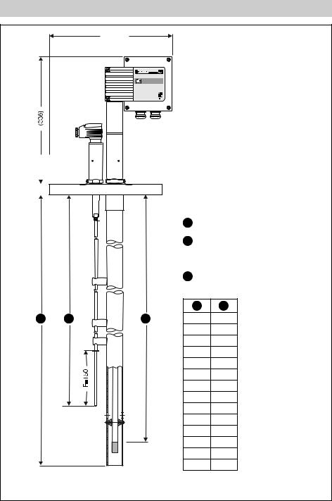
Dimensions
(330.5) |
NRG |
16-11 |
|
|
|
|
|
|
|
|
|
|
NRGT 26-1 |
|||||||
|
|
|
|
|
|
|
|
||||||||||||
|
|
|
|
|
|
|
|
|
|
|
|
|
|
|
|
|
|
|
|
|
|
|
|
|
|
|
|
|
|
|
|
|
|
|
|
|
|
|
|
|
|
|
|
|
|
|
|
|
|
|
|
|
|
|
|
|
|
|
|
|
|
|
|
|
|
|
|
|
|
|
|
|
|
|
|
|
|
|
|
|
|
|
|
|
|
|
|
|
|
|
|
|
|
|
|
|
|
|
|
|
|
|
|
|
|
|
|
|
|
|
|
|
|
|
|
|
|
|
|
NRGT 26-1
1 Max. length of installation at 238 °C
2 Measuring range
NRG 16-11
3 Range for low water level
1 2
1 |
3 |
2 |
358 |
300 |
462 400
568 500
673 600
779 700
884 800
989 900
1095 1000
1199 1100
1304 1200
1408 1300
1513 1400
1621 1500
2141 2000
Fig. 1 NRG 16-38S
3
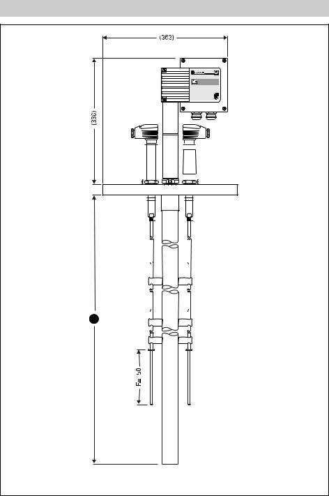
Dimensions
1
Fig. 2 NRG 16-39S
4
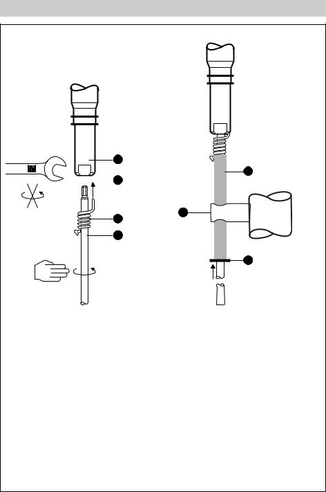
Parts Drawings
A
E
 B
B
U
C
D
F
Fig. 3 |
Fig. 4 |
5

Parts Drawings
G H I H
Fig. 5
J L N P
K M O
MAX 70 °C
MAX 95 %


 Q T
Q T 


S R
Fig. 6
6

Key
AMeasuring electrode
BBore
CSpring
DElectrode tip
EPTFE insulating tube
FSTARLOCK® retaining ring
GHousing screws M4
HCable gland M 16 (PG 9), M 20 (PG 16)
I Housing cover
J Switch for measuring range
KPotentiometer for lower measuring point (4 mA)
LLED “Liquid level 0 %”
MLED “Liquid level greater than 0 %, less than 100 %”
NLED “Liquid level 100 %”
OPotentiometer for upper measuring point
PTerminal lugs for voltage measurement
QThermal fuse Tmax 102 °C
RTerminal strips
SPE connection
TFixing nut
USpacer disc
7
Important Notes
Usage for the intended purpose
Use level electrodes type NRG 16-38 S, NRG 16-39 S only in conjunction with controller type NRS 1-7 for high-liquid level limiting (MAX. level alarm) and level monitoring in marine steam boilers and (pressurized) hot water installations.
Safety Note
The equipment must only be installed by qualified staff.
Qualified staff are those persons who – through adequate training in electrical engineering, the use and application of safety equipment in accordance with regulations concerning electrical safety systems, and first aid & accident prevention – have achieved a recognised level of competence appropriate to the installation and commissioning of this device.
Danger
When loosening the electrode steam or hot water might escape. This presents the danger of severe injuries to the whole body. It is
therefore essential not to remove the electrode unless the boiler pressure is verified to be zero.
The electrode is hot during operation.
This presents the danger of severe burns to hands and arms. Installation and maintenance work should only be carried out when the system is cold.
Classification pursuant to article 1 PED*)
Category |
|
none |
|
|
|
Designation |
|
Safety accessory |
|
|
|
CE marking |
|
no |
|
|
|
*) PED = Pressure Equipment Directive |
|
|
8
 Loading...