


DMX/DMXD/DMXH/DMXDH centrifugal pumps
Multistage, single/double suction, horizontally split volute type centrifugal pumps
PCN = 85392728 – 10/09 (E)
Original instructions
USER INSTRUCTIONS
Installation
Operation
Maintenance
SLEEVE/KTB CONFIGURATION
 These instructions must be read prior to installing, operating, using and maintaining the equipment.

DMX/DMXD/DMXH/DMXDH USER INSTRUCTIONS ENGLISH 85392728 - 10/09
CONTENTS |
PAGE |
||
1 |
INTRODUCTION AND SAFETY ...................... |
3 |
|
|
1.1 |
General ....................................................... |
3 |
|
1.2 |
CE marking and approvals ......................... |
3 |
|
1.3 |
Disclaimer................................................... |
3 |
|
1.4 |
Copyright .................................................... |
3 |
|
1.5 |
Duty conditions ........................................... |
3 |
|
1.6 |
Safety.......................................................... |
4 |
|
1.7 |
Warning labels............................................ |
7 |
|
1.8 |
Specific machine performance ................... |
8 |
|
1.9 |
Noise level .................................................. |
8 |
2 |
TRANSPORT AND STORAGE...................... |
10 |
|
|
2.1 |
Consignment receipt and unpacking ........ |
10 |
|
2.2 |
Handling ................................................... |
10 |
|
2.3 |
Lifting ........................................................ |
10 |
|
2.4 |
Extended storage ..................................... |
11 |
|
2.5 |
Recycling and end of product life ............. |
14 |
3 |
PUMP DESCRIPTION .................................... |
15 |
|
|
3.1 |
Configurations .......................................... |
15 |
|
3.2 |
Name nomenclature ................................. |
15 |
|
3.3 |
Design of major parts ............................... |
15 |
|
3.4 |
Performance and operating limits............. |
16 |
4 |
INSTALLATION .............................................. |
17 |
|
|
4.1 |
Location .................................................... |
17 |
|
4.2 |
Foundation................................................ |
17 |
|
4.3 |
Grouting.................................................... |
18 |
|
4.4 |
Initial alignment......................................... |
20 |
|
4.5 |
Piping........................................................ |
24 |
|
4.6 |
Electrical connections............................... |
26 |
|
4.7 |
Final shaft alignment check ...................... |
27 |
|
4.8 |
Protection systems ................................... |
27 |
5 COMMISSIONING, START-UP, OPERATION |
|||
|
AND SHUTDOWN.......................................... |
28 |
|
|
5.1 |
Precommissioning procedure................... |
28 |
|
5.2 |
Pump lubricants........................................ |
29 |
|
5.3 |
Impeller wearring clearance ..................... |
31 |
|
5.4 |
Direction of rotation .................................. |
31 |
|
|
PAGE |
5.5 |
Guarding................................................... |
31 |
5.6 |
Priming and auxiliary supplies.................. |
31 |
5.7 |
Starting the pump ..................................... |
31 |
5.8 |
Running or operation................................ |
31 |
5.9 |
Stopping and shutdown............................ |
32 |
5.10 |
Hydraulic, mechanical and electrical duty 32 |
|
6 MAINTENANCE ............................................. |
34 |
|
6.1 |
Maintenance schedule ............................. |
34 |
6.2 |
Spare parts ............................................... |
35 |
6.3Recommended spares and consumable
|
|
items......................................................... |
35 |
|
6.4 |
Tools required........................................... |
35 |
|
6.5 |
Fastener torques ...................................... |
35 |
|
6.6 |
Disassembly............................................. |
36 |
|
6.7 |
Examination of parts................................. |
39 |
|
6.8 |
Assembly of pump and seal ..................... |
40 |
7 FAULTS; CAUSES AND REMEDIES ........... |
47 |
||
8 |
PARTS LIST AND DRAWINGS..................... |
49 |
|
9 |
CERTIFICATION............................................ |
55 |
|
10 OTHER RELEVANT DOCUMENTATION AND |
|||
|
MANUALS...................................................... |
55 |
|
|
10.1 |
Supplementary user instruction manuals. 55 |
|
|
10.2 |
Change notes ........................................... |
55 |
|
10.3 |
Additional sources of information............. |
55 |
|
10.4 |
Customer Data Sheet............................... |
56 |
Page 2 of 60

DMX/DMXD/DMXH/DMXDH USER INSTRUCTIONS ENGLISH 85392728 - 10/09
1 INTRODUCTION AND SAFETY
1.1General
 These Instructions must always be kept close to product's operating location or directly with the product.
Flowserve's products are designed, developed and manufactured with state-of-the-art technologies in modern facilities. The unit is produced with great care and commitment to continuous quality control, utilising sophisticated quality techniques, and safety requirements.
Flowserve is committed to continuous quality improvement and being at service for any further information about the product in its installation and operation or about its support products, repair and diagnostic services.
These instructions are intended to facilitate familiarization with the product and its permitted use. Operating the product in compliance with these instructions is important to help ensure reliability in service and avoid risks. The instructions may not take into account local regulations; ensure such regulations are observed by all, including those installing the product. Always coordinate repair activity with operations personnel, and follow all plant safety requirements and applicable safety and health laws/regulations.
 These instructions must be read prior to installing, operating, using and maintaining the equipment in any region worldwide. The equipment must not be put into service until all the conditions relating to safety, noted in the instructions, have been met. Failure to follow and apply the present user instructions is considered to be misuse. Personal injury, product damage, delay or failure caused by misuse are not covered by the Flowserve warranty.
Where applicable, the Directives and any additional Approvals, cover important safety aspects relating to machinery and equipment and the satisfactory provision of technical documents and safety instructions. Where applicable this document incorporates information relevant to these Directives and Approvals. To confirm the Approvals applying and if the product is CE marked, check the serial number plate markings and the Certification, see section 9, Certification.
1.3Disclaimer
Information in these User Instructions is believed to be reliable. In spite of all the efforts of Flowserve to provide sound and all necessary information the content of this manual may appear insufficient and is not guaranteed by Flowserve as to its completeness or accuracy.
Flowserve manufactures products to exacting International Quality Management System Standards as certified and audited by external Quality Assurance organisations. Genuine parts and accessories have been designed, tested and incorporated into the products to help ensure continued product quality and performance in use. As Flowserve cannot test parts and accessories sourced from other vendors the incorrect incorporation of such parts and accessories may adversely affect the performance and safety features of the products. The failure to properly select, install or use authorised Flowserve parts and accessories is considered to be misuse. Damage or failure caused by misuse is not covered by Flowserve's warranty. In addition, any modification of Flowserve products or removal of original components may impair the safety of these products in their use.
1.4Copyright
All rights reserved. No part of these instructions may be reproduced, stored in a retrieval system or transmitted in any form or by any means without prior permission of Flowserve Corporation.
1.2CE marking and approvals
It is a legal requirement that machinery and equipment put into service within certain regions of the world shall conform with the applicable CE Marking Directives covering Machinery and, where applicable, Low Voltage Equipment, Electromagnetic Compatibility (EMC), Pressure Equipment Directive (PED) and Equipment for Potentially Explosive Atmospheres (ATEX).
1.5Duty conditions
This product has been selected to meet the specifications of your purchaser order. The acknowledgement of these conditions has been sent separately to the Purchaser. A copy should be kept with these instructions.
 The product must not be operated beyond the parameters specified for the application. If there is any doubt as to the suitability of the
Page 3 of 60

DMX/DMXD/DMXH/DMXDH USER INSTRUCTIONS ENGLISH 85392728 - 10/09
product for the application intended, contact Flowserve for advice, quoting the serial number.
If the conditions of service on your purchase order are going to be changed (for example liquid pumped, temperature or duty) it is requested that the user seeks Flowserve’s written agreement before start up.
1.6Safety
1.6.1 Summary of safety markings
These user instructions contain specific safety markings where non-observance of an instruction would cause hazards. The specific safety markings are:
 This symbol indicates electrical safety instructions where non-compliance will involve a high risk to personal safety or the loss of life.
 This symbol indicates safety instructions where non-compliance would affect personal safety and could result in loss of life.

 This symbol indicates “hazardous substances and toxic fluid” safety instructions where noncompliance would affect personal safety and could result in loss of life.
 This symbol indicates safety instructions where non-compliance will involve some risk to safe operation and personal safety and would damage the equipment or property.
 This symbol indicates explosive atmosphere marking according to ATEX. It is used in safety instructions where non-compliance in the hazardous area would cause the risk of an explosion.
 This symbol indicates is used in safety instructions to remind not to rub non-metallic surfaces with a dry cloth; ensure cloth is damp. It is used where non-compliance in the hazardous area would cause the risk of an explosion.
 This sign is not a safety symbol but indicates an important instruction in the assembly process.
1.6.2 Personnel qualification and training
All personnel involved in the operation, installation, inspection and maintenance of the unit must be qualified to carry out the work involved. If the personnel in question do not already possess the necessary knowledge and skill, appropriate training and instruction must be provided. If required the operator may commission the manufacturer / supplier to provide applicable training.
Always co-ordinate repair activity with operations and health and safety personnel, and follow all plant safety requirements and applicable safety and health laws and regulations.
1.6.3Safety action
This is a summary of conditions and actions to prevent injury to personnel and damage to the environment and to equipment. (For products used in potentially explosive atmospheres section 1.6.4 also applies.)
 Prevent excessive external pipe load Do not use pump as a support for piping. Do not mount expansion joints, unless authorized by Flowserve in writing, so that their force, due to internal pressure, acts on the pump flange.
 Ensure correct lubrication
(See section 5, Commissioning, startup, operation and shutdown.)
 Start the pump with outlet valve partly opened (Unless otherwise instructed at a specific point in the user instructions). This is recommended to minimize the risk of overloading at full flow and damaging the pump at zero flow. Pumps may be started with the valve further open only on installations where this situation cannot occur. The pump outlet control valve may need to be adjusted to comply with the duty following the run-up process. (See section 5, Commissioning start-up, operation and shutdown.)
 Never run the pump dry.
 Inlet valves to be fully open when pump is running. Running the pump at zero flow or below the recommended minimum flow continuously will cause damage to the pump and seals. Low flow rates may cause a reduction in pump/bearing life,
Page 4 of 60

DMX/DMXD/DMXH/DMXDH USER INSTRUCTIONS ENGLISH 85392728 - 10/09
overheating of the pump, instability and cavitation/ vibration.
 Do not run the pump at abnormally high or low flow rates. Operating at a flow rate higher than normal or at a flow rate with no backpressure on the pump may overload the motor and cause pump cavitation.
 Never do maintenance work when the unit is connected to power.

 When the pump is handling hazardous liquids care must be taken to avoid exposure to the liquid by appropriate sitting of the pump, limiting personnel access and by operator training. If the liquid is flammable and/or explosive, strict safety procedures must be applied.
 HANDLING COMPONENTS
Many precision parts have sharp corners and the wearing of appropriate safety gloves and equipment is required when handling these components. To lift heavy pieces above 25 kg (55 lb) use an appropriate crane for the mass and in accordance with current local regulations.
 Coupling guards must not be removed while the pump is operational.
 THERMAL SHOCK
Rapid changes in the temperature of the liquid within the pump will cause thermal shock, which can result in damage or breakage of components and should be avoided.
 HOT (and cold) PARTS
If hot or freezing components or auxiliary heating supplies can present a danger to operators and persons entering the immediate area action must be taken to avoid accidental contact. If complete protection is not possible, the machine access must be limited to maintenance staff only, with clear visual warnings and indicators to those entering the immediate area. Note: bearing housings must not be insulated and drive motors and bearings may be hot.
If the temperature is greater than 68 °C (154°F) or below -5 °C (20 °F) in a restricted zone, or exceeds local regulations, action as above shall be taken.
1.6.4Products used in potentially explosive atmospheres
 Measures are required to:
∙Avoid excessive temperature
∙Prevent the build up of explosive mixtures
∙Prevent the generation of sparks
∙Prevent leakages
∙Maintain the pump to avoid hazard
The following instructions for pumps and pump units when installed in potentially explosive atmospheres must be followed to help ensure explosion protection. Both electrical and non-electrical equipment must meet the requirements of European Directive 94/9/EC.
1.6.4.1Scope of compliance
 Use equipment only in the zone for which it is appropriate. Always check that the driver, drive coupling assembly, seal and pump equipment are suitably rated and/or certified for the classification of the specific atmosphere in which they are to be installed.
Where Flowserve has supplied only the bare shaft pump, the Ex rating applies only to the pump. The party responsible for assembling the ATEX pump set shall select the coupling, driver and any additional equipment, with the necessary CE Certificate/ Declaration of Conformity establishing it is suitable for the area in which it is to be installed.
The output from a variable frequency drive (VFD) can cause additional heating effects in the motor and so, for pumps sets with a VFD, the ATEX Certification for the motor must state that it is covers the situation where electrical supply is from the VFD. This particular requirement still applies even if the VFD is in a safe area.
1.6.4.2Marking
An example of ATEX equipment marking is shown below. The actual classification of the pump will be engraved on the nameplate.
Page 5 of 60

DMX/DMXD/DMXH/DMXDH USER INSTRUCTIONS ENGLISH 85392728 - 10/09
II 2 GD c IIB 135 ºC (T4)
Equipment Group
I = Mining
II = Non-mining
Category
2 or M2 = High level protection
3 = normal level of protection
Gas and/or Dust
G = Gas; D= Dust
c = Constructional safety
(in accordance with prEN13463-5)
Gas Group (Equipment Group II only)
IIA - Propane (Typical)
IIB - Ethylene (Typical)
IIC - Hydrogen (Typical)
Maximum surface temperature (Temperature Class) (See section 1.6.4.3.)
1.6.4.3Avoiding excessive surface temperatures
 ENSURE THE EQUIPMENT TEMPERATURE CLASS IS SUITABLE FOR THE HAZARD ZONE
Pumps have a temperature class as stated in the ATEX Ex rating on the nameplate. These are based on a maximum ambient temperature of 40 °C
(104 °F); refer to Flowserve for higher ambient temperatures.
The temperature of the liquid handled influences the surface temperature on the pump. The maximum permissible liquid temperature depends on the ATEX temperature class and must not exceed the values in the table that follows.
The temperature rise at the seals and bearings and due to the minimum permitted flow rate is taken into account in the temperatures stated.
Temperature |
Maximum surface |
Temperature limit of |
|
class to |
temperature |
||
liquid |
|||
prEN 13463-1 |
permitted |
||
|
|||
|
|
|
|
T6 |
85 °C (185 °F) |
Consult Flowserve |
|
T5 |
100 °C (212 °F) |
Consult Flowserve |
|
T4 |
135 °C (275 °F) |
115 °C (239 °F) * |
|
T3 |
200 °C (392 °F) |
180 °C (356 °F) * |
|
T2 |
300 °C (572 °F) |
275 °C (527 °F) * |
|
T1 |
450 °C (842 °F) |
400 °C (752 °F) * |
*The table only takes the ATEX temperature class into consideration. Pump design or material as well as component design or material may further limit the maximum working temperature of the liquid.
The responsibility for compliance with the specified maximum liquid temperature is with the plant operator.
If an explosive atmosphere exists during the installation, do not attempt to check the direction of rotation by starting the pump unfilled. Even a short run time may give a high temperature resulting from contact between rotating and stationary components. Where there is any risk of the pump being run against a closed valve generating high liquid and casing external surface temperatures, the users shall fit an external surface temperature protection device.
Avoid mechanical, hydraulic or electrical overload by using motor overload trips, temperature monitor or a power monitor and make routine vibration monitoring checks.
In dirty or dusty environments, regular checks shall be made and dirt removed from areas around close clearances, bearing housings and motors.
1.6.4.4Preventing the build up of explosive mixtures
 ENSURE THE PUMP IS PROPERLY FILLED AND VENTED AND DOES NOT RUN DRY
Ensure the pump and relevant suction and discharge pipeline system is totally filled with liquid at all times during the pump operation, so that an explosive atmosphere is prevented. In addition it is essential to make sure that seal chambers, auxiliary shaft seal systems and any heating and cooling systems are properly filled. If the operation of the system cannot avoid this condition, users shall fit an appropriate dry run protection device (e.g. liquid detection or a power monitor).
To avoid potential hazards from fugitive emissions of vapor or gas to atmosphere the surrounding area shall be well ventilated.
1.6.4.5Preventing sparks
 To prevent a potential hazard from mechanical contact, the coupling guard must be non-sparking and anti-static for Category 2.
To avoid the potential hazard from random induced current generating a spark, the baseplate shall be properly grounded.
Avoid electrostatic charge: do not rub non-metallic
Page 6 of 60

DMX/DMXD/DMXH/DMXDH USER INSTRUCTIONS ENGLISH 85392728 - 10/09
surfaces with a dry cloth; ensure cloth is damp.
The coupling must be selected to comply with 94/9/EC and correct alignment must be maintained.
1.6.4.6Preventing leakage
 The pump shall only be used to handle liquids for which it has been approved to have the correct corrosion resistance.
Avoid entrapment of liquid in the pump and associated piping due to closing of suction and discharge valves, which could cause dangerous excessive pressures to occur if there is heat input to the liquid. This can occur if the pump is stationary or running.
Bursting of liquid containing parts due to freezing must be avoided by draining or protecting the pump and ancillary systems.
Where there is the potential hazard of a loss of a seal barrier fluid or external flush, the fluid shall be monitored.
If leakage of liquid to atmosphere can result in a hazard, then a liquid detection device shall be installed.
1.6.4.7Maintenance to avoid the hazard
 CORRECT MAINTENANCE IS REQUIRED TO AVOID POTENTIAL HAZARDS WHICH GIVE A RISK OF EXPLOSION
The responsibility for compliance with maintenance instructions is with the plant owner or operator.
To avoid potential explosion hazards during maintenance, the tools, cleaning and painting materials used must not give rise to sparking or adversely affect the ambient conditions. Where there is a risk from such tools or materials, maintenance must be conducted in a safe area.
A maintenance plan and schedule shall be adopted. (See section 6, Maintenance).
1.7Warning labels
Page 7 of 60
DMX/DMXD/DMXH/DMXDH USER INSTRUCTIONS ENGLISH 85392728 - 10/09
Oil lubricated units only:
1.8Specific machine performance
For performance parameters see 10.4 Customer Data Sheet. When the contract requirement specifies these to be incorporated into User Instructions these are included here. Where performance data has been supplied separately to the purchaser these should be obtained and retained with these User Instructions if required.
1.9Noise level
Attention must be given to the exposure of personnel to the noise, and local legislation will define when guidance to personnel on noise limitation is required, and when noise exposure reduction is mandatory. This is typically 80 to 85 dBA.
The usual approach is to control the exposure time to the noise or to enclose the machine to reduce emitted sound. You may have already specified a limiting noise level when the equipment was ordered, however if no noise requirements were defined, then attention is drawn to the following table to give an indication of equipment noise level so that you can take the appropriate action in your plant.
Pump noise level is dependent on a number of operational factors, flow rate, pipework design and acoustic characteristics of the building, and so the values given are subject to a 3 dBA tolerance and cannot be guaranteed.
1.9.1Pump noise levels
The following tables may be used to determine the estimated sound pressure levels (SPL), expressed in dBA (dB), for DMX/DMXD/DMXH/DMXDH pumps.
The values shown have been derived from actual noise test data and are based on the following conditions:
a)Equipment is located in a free field above a reflecting plane in which the reduction in noise level in all directions is 6 dB in each octave band for each doubling of distance.
b)Background noise is 10 dB (minimum) below all noise levels in each octave band.
c)The values shown are at a distance of 1 m (3.281 ft), horizontally from major pump surfaces and 1.5 m (4.78 ft) above the floor using the
standard pressure reference of 20 µPa (0.00002 N/m2).
d)Overall noise level, dBA ("A" scale) is determined at points of maximum noise level, and the values of all mid-band frequencies are basis "C" scale readings.
1.9.2Overall noise level
Tables below show dBA levels for two stage and three or more stage pumps, based on the best efficiency point BEP at design RPM and required impeller diameter.
For specific gravities less than 1.0, use 1.0 specific gravity. For specific gravities above 1.0, use the actual specific gravity.
When the required condition flow falls outside the range of 75% to 125% of BEP, a Part Load Correction (PLC) must be added to the noise levels as follows:
Percent of BEP at required Impeller |
|
PLC DB |
Diameter |
|
|
74 to 62 % or 126 to 136 % |
+1 |
|
61 to 50 % or 137 to 150 % |
+2 |
|
49 to 38 % |
+3 |
|
37 to 25 % |
+4 |
|
|
|
|
Brake Horse Power at Best Efficiency |
|
dBA |
Point. |
|
|
|
|
|
2 Stage pump |
|
|
250 to 350 |
|
87 |
350 to 500 |
|
88 |
500 to 700 |
|
89 |
700 to 940 |
|
90 |
940 to 1100 |
|
91 |
1100 to 1300 |
|
92 |
1300 to 1500 |
|
93 |
Above 1500, contact Flowserve |
|
94 |
Page 8 of 60

DMX/DMXD/DMXH/DMXDH USER INSTRUCTIONS ENGLISH 85392728 - 10/09
Brake Horse Power at Best Efficiency |
dBA |
|
Point. |
||
|
||
3 to 14 Stages |
|
|
90 to 110 |
79 |
|
110 to 140 |
80 |
|
140 to 180 |
81 |
|
180 to 220 |
82 |
|
220 to 280 |
83 |
|
280 to 360 |
84 |
|
360 to 450 |
85 |
|
450 to 560 |
86 |
|
560 to 720 |
87 |
|
720 to 900 |
88 |
|
900 to 1125 |
89 |
|
1125 to 1400 |
90 |
|
1400 to 1800 |
91 |
|
1800 to 2250 |
92 |
|
2250 to 2800 |
93 |
|
2800 to 3600 |
94 |
|
3600 to 4500 |
95 |
|
4500 to 5700 |
96 |
|
5700 to 7200 |
97 |
|
7200 to 9000 |
98 |
|
9000 to 11,000 |
99 |
|
11,000 to 14,000 |
100 |
1.9.3Combined noise levels for pump and driver components
When two or more sources produce noises that are sufficiently unrelated (so that interference effects do not occur) the total combined noise level may be obtained by a simple addition of dB values according to the below table.
Difference between two |
Add to higher level to |
levels to be Combined, dB |
obtain Combined level, dB |
0 |
3 |
1 |
2.5 |
2 |
2 |
4 |
1.5 |
6 |
1 |
9 |
0.5 |
10 |
0 |
Page 9 of 60

DMX/DMXD/DMXH/DMXDH USER INSTRUCTIONS ENGLISH 85392728 - 10/09
2 TRANSPORT AND STORAGE
2.1Consignment receipt and unpacking
Immediately after receipt of the equipment it must be checked against the delivery/shipping documents for its completeness and that there has been no damage in transportation.
Any shortage and or damage must be reported immediately to Flowserve and received in writing within one month of receipt of the equipment. Later claims cannot be accepted.
Check any crates, boxes and wrappings for any accessories or spare parts which may be packed separately with the equipment or attached to side walls of the box or equipment.
Each product has a unique serial number. Check that this number corresponds with that advised and always quote this number in correspondence as well as when ordering spare parts or further accessories.
2.1.1Receipt inspection
 The following information regarding receiving is only offered as a general guideline to the customer. Flowserve requires that all receiving
be conducted in accordance with specifications set forth in Chapter 3, Jobsite Receiving and Protection from API Recommended Practices 686/PIP REIE 686, First Edition.
The pump and its associated equipment were carefully inspected at the factory prior to shipment to ensure quality compliance. It is suggested that the pump be inspected upon arrival and that any irregularities or damage be reported to the carrier immediately.
The condition of the skid and covering is indicative of the way the shipment was handled. Broken skids, torn coverings, bent hold-down bolts, broken straps, etc. indicate rough handling.
The protective covers on the pump nozzles should be in place and undamaged.
2.1.2Unpacking
The pump should arrive already mounted on the baseplate and it is therefore suggested that the unpacking of the equipment should proceed per instruction as outlined in this manual.
In general, care is to be taken when removing crating, coverings, and strapping in order not to damage any auxiliary equipment and/or the paint finish.
2.1.3Paint/rust preventive
Internal parts of the pump and bearing housings are protected prior to shipment with a rust preventive such as Dasco guard 2408M. This can be removed with petroleum solvents.
External non-machined surfaces are painted with one of applicable Flowserve coating.
Parts ordered separately are protected with a rust preventive such as Dasco guard 2408M. This can be removed with petroleum solvents.
2.2Handling
Boxes, crates, pallets or cartons may be unloaded using forklift vehicles or slings dependent on their size and construction.
2.3Lifting
 To avoid distortion, the pump unit should be lifted as shown.
 TRAINED PERSONNEL
A crane must be used for all pump sets in excess of 25 kg (55 lb). Fully trained personnel must carry out lifting, in accordance with local regulations. The driver and pump weights are recorded on their respective nameplates or mass plates.
2.3.1Lifting equipment
 The following information regarding lifting is only offered as a general guideline. Flowserve requires that all lifting and rigging be performed in accordance with specifications set forth in Chapter 2, Lifting and Rigging from API Recommended Practices 686/PIP REIE 686, First Edition.
 EQUIPMENT CAPACITY
Make sure that any equipment used to lift the pump or any other of its components is capable of supporting the total weight encountered. Make sure that all parts are properly rigged before attempting to lift.
Page 10 of 60
DMX/DMXD/DMXH/DMXDH USER INSTRUCTIONS ENGLISH 85392728 - 10/09
2.3.2To lift unit
 The complete unit with pump, driver and auxiliary equipment all mounted on the baseplate can NOT be lifted as a unit. Driver must be removed from baseplate before lifting. To lift unit sling baseplate from all lifting eyes. Failure to do this may result in permanent deformation of baseplate. Damage to baseplate caused by mishandling or improper setting prior to grouting is not covered by Flowserve’s warranty.
2.3.3To lift driver
Refer to driver manufacturers instructions.
2.3.4To lift pump
Install sling from overhead hoist and under bearing housing mounting brackets (cast portion of casing where bearing housings attach).
Proper lifting practice for pump
 LIFTING PRACTICE
Do not lift entire pump from cast lifting lugs on upper half casings. These lugs are for lifting upper half casing only.
2.3.5To lift half casing
To lift upper half casing, rig to overhead hoist from cast lifting lugs provided.
Proper lifting practice for upper case
To lift the pump bottom half casing, slings can be attached to the pump feet, casing boltholes or padded slings can be used around the outer casing.
2.3.6To lift pump rotor
Using slings that will not damage shaft, rig around shaft close to the impellers and to overhead hoist. Carefully lift rotor from lower half casing.
Proper lifting practice for pump
2.4Extended storage
 The following information regarding receiving is only offered as a general guideline. Flowserve requires that all receiving be conducted in accordance with specifications set forth in Chapter 3,
Jobsite Receiving and Protection from API recommended Practices 686/PIP REIE 686, First Edition.
During extended periods of storage prior to installation and from the time of installation until commercial operation, precautions must be taken to protect the pump from deterioration. The various parts of the pump are protected prior to shipment by applying varying grades of preservative and paint. However, during shipment and handling, the preservatives are subjected to conditions that can cause their removal. Also, during extended periods of time, the preservatives may deteriorate. The following procedures should be followed to prevent deterioration of the pump during the extended storage period. These procedures may also be supplemented by the experience of the person(s) performing the tasks.
It should be noted, that unless otherwise agreed to, full responsibility and costs associated with the storage and inspection of this equipment rests with the customer.
Page 11 of 60

DMX/DMXD/DMXH/DMXDH USER INSTRUCTIONS ENGLISH 85392728 - 10/09
 If pump is equipped with a mechanical seal and is stored or has not been run for 1 year or more, the mechanical seal must be removed before start-up and faces re-lapped to guard against the possibility of seal leakage. When reinstalling the seal, new “O” rings and gaskets must be used.
2.4.1Pump inspection upon arrival
When the pump is received, it should be inspected for damage or other signs of rough handling. Any damage if found should be reported to the carrier immediately.
Inspect the preservative coating on the various parts. If necessary, renew the preservative in areas where it has rubbed off or scraped.
Inspect all painted surfaces. If necessary, touch up the areas where paint has been chipped or scraped.
Inspect all covers over pump openings and piping connections. If covers or seals for the covers are damaged or loose, they are to be removed, and a visual inspection made of the accessible interior areas for accumulation of foreign materials or water. If necessary, clean and re-coat the interior parts with preservative to restore the parts to the “as shipped” condition. Install or replace covers and fasten secure.
2.4.2Storage area
When selecting a storage area, the following should be taken into consideration:
a)The deterioration of the equipment will be proportionate to the class/type of storage provided.
b)The expenses involved in restoring the equipment at time of operation will be proportionate to the class/type of storage provided.
2.4.3Storage preferred (dry)
If at all possible, the pump and its components should be stored indoors where they will be protected from the elements. If it is not possible to store the pump and its components indoors, precautions must be taken to protect them from the elements. Regardless of whether storage is inside or outside, the storage area should be vibration-free. All boxes that are marked for inside storage must be stored indoors. Coverings of heavy gauge plastic sheets, canvas, waterproof burlap or other suitable coverings should protect the pump and its components from
dirt, dust, rain, snow or other unfavorable conditions when stored outdoors.
All equipment must be placed upon skids or blocks to prevent contact with the ground and surface contaminants. Equipment must be adequately supported to prevent distortion and bending.
2.4.3.1Rotor storage
It is recommended that pump rotor be removed from pump and stored vertically. Rotors may also be stored horizontally in the pump. Rotors that have to be stored horizontally outside the pump must be supported close to impeller to eliminate sag that may cause rotor to take a permanent set.
2.4.3.2Customer inspection
The stored equipment is to be placed on a periodic inspection schedule by the customer.
 The responsibility for setting up an inspection and maintenance schedule rests with the customer and will be dependent upon the class/type of storage provided. It will be expected that initially inspection would occur weekly, then depending upon the inspection reports being favorable or unfavorable, inspection would continue weekly, monthly, or quarterly, as may be determined. Inspection reports must be kept on file.
Every inspection should consist of a general surface inspection.
a)Pump supports are firmly in place.
b)Pump covers over openings are firmly in place.
c)Pump coverings, plastics or tarps, are firmly in place. Any holes or tears must be repaired to prevent entrance of dirt or water.
d)Pump covers are periodically removed from openings and interior accessible areas inspected. If surface rusting has occurred, clean and repaint or re-coat with preservative.
e)If rusting occurs on exterior surfaces, clean and repaint or re-coat with preservative.
f)Loosen casing drain plugs to allow seepage of any accumulated moisture.
g)If the rotor is stored horizontally, rotate pump rotor 1-1/4 revolutions at least once a month to prevent rotor from taking a permanent set.
Page 12 of 60

DMX/DMXD/DMXH/DMXDH USER INSTRUCTIONS ENGLISH 85392728 - 10/09
 Make sure bearings have adequate lubrication before turning rotor.
 The oil inlet blanking plates should be removed and a small amount of oil injected into the bearings before turning. Refit blanking plates.
h)Periodically remove bearing covers and inspect for accumulation of moisture, rust and foreign material. As required, clean bearings and bearing housing and re-preserve. Install bearing cover and secure to assure maximum protection. Bearings removed for storage should be coated with preservative, wrapped in oil/wax paper, and stored in a warm dry area.
i)Check individually wrapped parts for signs of deterioration. If necessary, renew preservative and wrapping.
 If storage is over one month, Instrumentation (Controls, Electrical devices, Temperature switches) should be removed and placed in a climate control environment if Instrumentation is not powered up.
2.4.3.3Prior to installation maintenance
Six months prior to the scheduled installation date, a Flowserve representative is to be employed to conduct an inspection. All costs involved during inspection, dismantling, restoration, replacement of parts, and reassembly will be the responsibility of the customer. The customer will supply all necessary labor, tools, and cranes. This inspection will include (not necessarily in its entirety) but not be limited to the following:
a)An inspection of all periodic inspection records as kept on file by the customer, and all inspection reports that have been compiled during the storage period.
b)An inspection of the storage area to determine the “as stored” condition of the equipment prior to any protection being removed.
c)An inspection of the equipment with protection covers and flange covers removed.
d)Depending upon the length of time the equipment was stored, the class/type of storage provided, (i.e.: indoor, heated, unheated, ground floor, concrete floor, out-of-doors, under roof, no roof,
waterproof coverings, on concrete, on ground) and as a result of the inspection of a, b and c above, Flowserve representative may require a partial or complete dismantling of the equipment.
e)Dismantling may necessitate restoration of painted or preserved surfaces, and/or replacement of gaskets, “O” rings and mechanical seal and bearings. Use only Flowserve recommended replacement materials.
Upon completion of the inspection, the Flowserve representative shall submit a report to the Customer, and to the Manager of Customer Service, stating in detail the result of the inspection.
If there are any discrepancies identified, it is the customer's responsibility for correction before initial startup.
2.4.4Storage non-preferred (wet)
It is not recommended that the rotor be subjected to extended periods of submergence or wetting prior to start-up. However, it is recognized that in some cases, a long period of time may lapse from installation until commercial operation.
If the pump must be stored after being installed and wetted, the following inspection and maintenance should be performed.
∙Isolate the pump with valving - tag (seal) all valves.
∙Preserve the pump internals.
 If storage is over one month, Instrumentation (Controls, Electrical devices, Temperature switches) should be removed and placed in a climate controlled environment if Instrumentation is not powered up.
 Electric motors (pump driver) should not be stored in damp places without special protection (refer to motor manufacturer’s instructions).
2.4.4.1Corrosive pumpage.
Fill entirely the pump with an approved preservative such as #2004-Chempagard 9 from Chempak. The pump should be filled to highest level possible, affording the greatest protection possible to all internal parts of the pump.
Page 13 of 60

DMX/DMXD/DMXH/DMXDH USER INSTRUCTIONS ENGLISH 85392728 - 10/09
This solution, when drained, will result in a thin residual oil film (less than 0.0127 mm (0.0005 in.)) on all internals after the water has evaporated. This residue provides added corrosion protection until pump is again filled with liquid or put into service.
 Pump cannot be fully drained. Volutes in the lower half cannot be drained below the bottom of the main casing bore.
2.4.4.2Non-corrosive pumpage.
Fill pump with pumpage to the highest level possible. Open periodically drain connection to drain off any moisture that may have accumulated. Refill to highest level possible. Drain and inspect pump prior to startup.
a)Rotate pump rotor 1-1/4 revolutions at least once a month.
 Make sure bearings have adequate lubrication before turning rotor.
b)Periodically remove bearing covers and inspect for accumulation of moisture, rust and foreign material. As required, clean bearings and bearing housing and re-preserve. Install bearing cover and secure to assure maximum protection.
2.4.4.3Painting and preservation
Paints and preservatives used are either Flowserve standard or special as required by the contract specification. Refer to 2.1.3, Paint/Rust Preventive for the description of paints and preservatives used in this order or contact the branch office through which the order was placed.
2.5Recycling and end of product life
At the end of the service life of the product or its parts, the relevant materials and parts should be recycled or disposed of using an environmentally acceptable method and local regulations. If the product contains substances which are harmful to the environment, these should be removed and disposed of in accordance with current regulations. This also includes the liquids and or gases in the "seal system" or other utilities.
 Make sure that hazardous substances or toxic fluids are disposed of safely and that the correct personal protective equipment is used. The safety
specifications must be in accordance with the current regulations at all times.
Page 14 of 60
DMX/DMXD/DMXH/DMXDH USER INSTRUCTIONS ENGLISH 85392728 - 10/09
3 PUMP DESCRIPTION
The “DMX” is a multistage single or double suction, opposed impeller, horizontally split volute pump.
The suction and discharge nozzles are cast integral with the lower half casing. Rotating parts are accessible by removing the upper half casing, which can be removed without breaking suction and discharge piping.
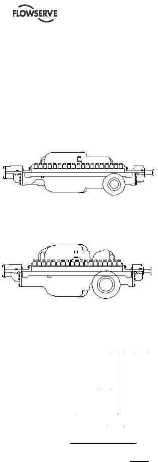
3.1Configurations
The DMX can have the following configurations:
3.1.1Single suction
Single suction configuration
Single suction impeller at first stage (DMX)
3.1.2Double suction
Double suction configuration
Double suction impeller at the first stage (DMXD)
DMX= Single suction standard pressure DMXD = Double suction standard pressure DMXH = Single suction high pressure DMXDH = Double suction high pressure
3.3Design of major parts
3.3.1Casing
The casing provides for immediate containment of the liquid being pumped, while directing the flow of liquid from the suction nozzle to the impellers and subsequently through the volute to the discharge nozzle.
The casing halves are sealed by the use of a gasket and are joined together by studs, which are installed in the lower half casing and fastened with washers and cap-nuts.
3.3.2Impellers
The series’ impellers are single suction, enclosed type, and one-piece construction and are dynamically balanced. They are fitted with renewable impeller rings (front and back), which are held in place by headless set-screws.
The impellers are keyed and have a shrink fit to the pump shaft. They are held in axial position by a split ring.
3.3.3Casing rings
Casing rings are positioned over the impeller front rings. These rings are tubular and renewable.
3.3.4Channel rings
Renewable cast channel rings are positioned over the impeller back rings. They divide the casing into stages. These rings are horizontally split and are held together by shoulder screws or dowel pins.
3.2Name nomenclature
The pump nomenclature is: |
3X10DMX10 |
The 3 is the pump discharge size
The X is the separator
The 10 is the nominal impeller size
The DMX is pump type
The 10 is the number of stages and depending on pump size, they go from 2 to 14 stages
3.3.5Center sleeve
A renewable type center sleeve is used under the center bushing. The center sleeve is tubular and keyed to the shaft (via the impeller key).
3.3.6Center bushing
The renewable center bushing is horizontally split, and the two halves are held together by socket head cap screws and taper dowel pins. It is held in position by the raised annular ring of the bushing engaging the annular groove in the casing. The center bushing, in conjunction with center sleeve, divides the casing at the center (back to back) impellers.
Page 15 of 60

DMX/DMXD/DMXH/DMXDH USER INSTRUCTIONS ENGLISH 85392728 - 10/09
3.3.7Throttling sleeve
Renewable type throttling sleeve is used under the throttling bushing. The throttling sleeve is tubular, keyed, has a shrink fit to the shaft, and is held in position by a split ring.
3.3.8Throttling bushing
Renewable type throttling bushing is used. It is held in position by the raised annular ring of the bushing engaging the annular groove in the casing. The throttling bushing, in conjunction with the throttling sleeve, allows pressure to be bled off through the balance line, so that pressure on the Seal Chambers is balanced. The throttling bushing also balances the axial thrust of the pump rotor.
3.3.9Crossover sleeve
A renewable type crossover sleeve under crossover bushing is only used on double suction pumps (DMXD/DMXDH). The crossover sleeve is tubular, keyed, has a shrink fit to the shaft, and is held in position by a split ring.
3.3.10 Crossover bushing
A renewable type crossover bushing is only used on double suction pumps (DMXD/DMXDH). The crossover bushing is horizontally split, and the two halves are held together by taper dowel pins. It is held in position by the raised annular ring of the bushing engaging the annular groove in the casing. The crossover bushing, in conjunction with crossover sleeve, controls the leakage between the first and second stage impellers.
3.3.11 Shaft
The high strength shaft is ground over its entire length to close tolerances. The shaft is designed to transmit the required power without vibration and is stepped at each impeller fit for ease of assembly and disassembly.
3.3.12 Bearings
The sleeve bearings are carbon steel backed, babbitt lined, sleeve type insert bearings. The renewable bearing inserts are mounted in bearing housings kept from rotating by means of stop pins.
Each bearing is lubricated by an external pressure supply system.
The thrust bearing is of the titling type with pads on each side of the shaft mounted thrust
collar. It is capable of transmitting the thrust load in either direction. It is lubricated from the
pressure lubrication system.
3.3.13 Seal Chambers
The Seal Chambers are cast integral with the casing. Your pump is typically shipped with the mechanical seal already installed.
The mechanical seal is designed to suit each application. This creates the correct seal loading face when seal gland is bolted in place.
Cartridge type mechanical seals are preset at the seal manufacturer’s facility and require no field settings. The seal installation should be checked before startup.
Refer to the mechanical seal manufacturers drawing and instructions found in section 8 of this manual for detailed information.
3.4Performance and operating limits
Refer to section 10.4 Customer Data Sheet.
Page 16 of 60

DMX/DMXD/DMXH/DMXDH USER INSTRUCTIONS ENGLISH 85392728 - 10/09
4 INSTALLATION
 The installation/commissioning of this equipment must be conducted in accordance with API Recommended Practices 686/PIP REIE 686 - First Edition.
Copies of API Recommended ‘Practices’ 686/PIP REIE 686 - First Edition may be obtained from
America Petroleum Institute
1220 L Street, N.W.
Washington, D.C. 20005.
Telephone: (202) 682-8000.
4.1Location
Install the unit close to the source of the liquid to be pumped.
 Equipment operated in hazardous locations must comply with the relevant explosion protection regulations. See section 1.6.4, Products used in potentially explosive atmospheres.
When selecting the location, be sure to allow adequate space for operation as well as for maintenance operations involving dismantling and inspections of parts.
Headroom is an important consideration as an overhead lift of some type is required.
4.2Foundation
 The following information regarding foundation is only offered as a general guideline. Flowserve requires that all foundations be designed and installed in accordance with specifications set forth in Chapter 4, Foundations from API Recommended Practices 686/PIP REIE 686, First Edition.
The design of foundation is not the responsibility of Flowserve. It is therefore recommended that the customer consult a competent specialist skilled in the field of foundations, to insure proper design/installation of the foundation.
The foundation should be properly prepared according to the planned grouting method. See 4.3 Grouting for details.
The foundation should be rigid and substantial to support the baseplate at all points to prevent any pump vibration and to permanently.
The most satisfactory foundations are made of reinforced concrete. These should be poured well in advance of the installation to allow proper time for drying and curing.
The General Arrangement Drawing will show required anchor bolt locations and size of bolts.
Allow a little more than the specified threaded bolt length above the rail of the baseplate. The excess can always be cut off if it is not needed.
A clean rough-finish top surface is required when applying grout.
4.2.1Installation check list
a)Level Baseplate.
b)Preliminary Alignment.
c)Grout Baseplate - Check Foundation Bolts
d)Alignment Shaft/Coupling.
e)Piping installed – correct vent, gauge, valve, suction strainer and pipe support locations?
f)Check Coupling Alignment.
g)Coupling guard correctly installed?
4.2.2Level the baseplate
 The following information regarding leveling of equipment is only offered as a general guideline. Flowserve requires that all leveling of equipment be performed in accordance with specifications set forth in Chapter 5, Mounting Plate Grouting from API Recommended Practices 686/PIP REIE 686, First Edition.
Before putting the unit on the foundation, thoroughly clean the top of the foundation. Break off any loose pieces of cement and roughen the top with a chisel to afford a good hold for grout.
 When lifting baseplate with pump, sling baseplate from all lifting eyes provided. Failure to do
Page 17 of 60

DMX/DMXD/DMXH/DMXDH USER INSTRUCTIONS ENGLISH 85392728 - 10/09
this may result in permanent deformation of baseplate.
 Pump, driver auxiliary equipment and piping shall be removed from the baseplate before leveling the baseplate.
Locate the baseplate in its proper position on the concrete block together with the leveling screws as shown in the General Arrangement Drawing.
Using a precision level across the machined surfaces of the pump and driver mounting pads, adjust leveling screws as necessary to ensure that baseplate is leveled in all directions.
When the baseplate is leveled, snug the foundation bolts, but do not completely tighten.
4.2.3Preliminary alignment
Using the previous procedure, adjust baseplate until pump and driver are within 0.076 mm (0.003 in.).
4.3Grouting
 The following information regarding grouting is only offered as a general guideline. Flowserve requires that all grouting be installed in accordance with specifications set forth in Chapter 5,
Mounting Plate Grouting from API Recommended Practices 686/PIP REIE 686, First Edition. Refer to
API 610 - Eighth Edition - Appendix `L` for baseplate grouting requirements. It is recommended that the customer consult a competent specialist skilled in the field of grouting, to insure the proper installation of all grouting.
The following ASTM Specifications are furnished as references for test methods used in conjunction with installation of grouting materials and should be used to obtain proper results:
ASTM C 78-84, Test Method for Flexural Strength for Concrete
ASTM C 109-90, Test Method for Compressive Strength of Hydraulic Cement Mortars – Modified
ASTM C 469-87a, Test Method for Static Modulus of Elasticity and Poisson’s Ratio of Concrete in Compression
ASTM C 496-90, Test Method for Splitting Tensile Strength of Cylindrical Concrete Specimens
ASTM C 531-85, Test Method for Linear Shrinkage and Coefficient of Thermal Expansion of Chemical Resistant Grouts and Monolithic Surfacing - Modified
ASTM C 666-90, Test Method for Resistance of Concrete to Rapid Freezing and Thawing
ASTM C 939-87, Test Method for Flow of Grout for Preplaced Aggregate Concrete (Flow Cone Method)
ASTM C 942-86, Test Method for Compressive Strength of Grouts for Preplaced Aggregate Concrete in the Laboratory
ASTM C 1090-88, Test Method for Measuring Changes in Height of Cylindrical Specimens from Hydraulic Cement Grout
ASTM C 1107-91, Standard Specification for Packaged Hydraulic-Cement Grout (Non-Shrink)
(CRD-C 621-92), ACI 351, Grouting for Support of Equipment and Machinery
24-Hour Test, MBT Test Method for Grout Performance
 Minimum requirements for epoxy grout (typical properties at 23 oC (73 oF))
ASTM D-635, Fire Resistant
ASTM C-579B, Minimum Compressive Strength – 12000 psi
ASTM C-827, Height Change @ 38 oC (100 oF) – Positive – Effective Bearing Area – 95%
ASTM C-1181, Maximum Creep in 1 Year – 1.6X10⁻³ in./in. at 140 oF, 400 psi
ASTM C-307, Minimum Tensile Strength – 12.4 Mpa (1800 psi)
ASTM C-580, Minimum Flexural Strength – 26.2 Mpa (3800 psi)
ASTM C-580, Minimum Flexural Secant Modulus – 1.2X10⁴ Mpa (1.8X10⁶ psi)
ASTM C-531, Maximum Coefficient of Expansion – 17X10-6 in./in./oF. Maximum Peak Exotherm 1000 g (35.27 oz.) insulated – 35 oC (95 oF). Full Aggregate Must Be Used.
Page 18 of 60
 Loading...