


Limitorque Actuation Systems
FCD LMAIM5001-00
(Replaces 435-11000)
Limitorque®
DDC-100 Master Station II
Installation and Operation Manual

Flow Control Division
Limitorque Actuation Systems
Master Station
Installation and Operation Manual
©2004 Copyright Flowserve Corporation. All rights reserved.
Printed in the United States of America.
Disclaimer
No part of this book shall be reproduced, stored in a retrieval system, or transmitted by any means, electronic, mechanical, photocopying, recording, or otherwise without the written permission from Flowserve. While every precaution has been taken in the preparation of the book, the publisher assumes no responsibility for errors or omissions. Neither is any liability assumed for damages resulting from the use of the information contained herein.
This document is proprietary information of Flowserve furnished for customer use ONLY. No other uses are authorized without written permission of Flowserve.
Flowserve reserves the right to make changes, without notice, to this document and the products it describes. Flowserve shall not be liable for technical or editorial errors or omissions made herein; nor for incidental or consequential damages resulting from the furnishing, performance or use of this document.
This manual contains information that is correct to the best of Flowserve’s knowledge. It is intended to be a guide and should not be considered as a sole source of technical instruction, replacing good technical judgment, since all possible situations cannot be anticipated. If there is any doubt as to exact installation, configuration, and/or use, please contact Flowserve at 1-800-225-6989.
The choice of system components is the responsibility of the buyer, and how they are used cannot be the liability of Flowserve Corporation. However, Flowserve’s sales team and application engineers are always available to assist you in making your decision.
MS-DOS® is a registered trademark of Microsoft Corporation.
IBM-PC® is a registered trademark of International Business Machines Corporation.
Belden® is a registered trademark of Belden, a division of Cooper Industries, Inc.
2 |
DDC-100 Master Station II Installation and Operation Manual |
FCD LMAIM5001-00 |

Flow Control Division
Limitorque Actuation Systems
FCD LMAIM5001-00 |
DDC-100 Master Station II Installation and Operation Manual |
3 |

Flow Control Division
Limitorque Actuation Systems
4 |
DDC-100 Master Station II Installation and Operation Manual |
FCD LMAIM5001-00 |

Flow Control Division
Limitorque Actuation Systems
1Introduction
1.1 Overview
The Limitorque Master Station II is a revolutionary step forward in control technology. The device is capable of controlling up to 250 actuators, offers full redundancy, provides easy-to-use HMI interfaces, and allows for high-speed data-transfer via a Modbus DCS port or Modbus Ethernet port. In addition, a built-in web server can be used for monitoring network status from any remote station using TCP/IP. Web server operation is covered in Section 18.
1.2User Rights Overview
The Master Station requires users to login. Three user role levels are provided: View, Control, Configure.
Each role includes the rights of the lesser roles, i.e. Control includes View’s rights, and Configure includes
Control’s rights and View’s rights.
View: the user can view the network status and the activity log. No control or configuration functionality is available.
Control: in addition to View’s rights, the user has the ability to control MOVs.
Configure: in addition to Control’s rights, the user has the ability to configure the Master Station and the Network.
The default passwords for each role are:
View: 100
Control: 200
Configure: 300
These passwords can be changed by the Configure user. Changing passwords is discussed in Section 9.
FCD LMAIM5001-00 |
DDC-100 Master Station II Installation and Operation Manual |
5 |
Flow Control Division
Limitorque Actuation Systems
1.3Login
When the Master Station starts, it loads the default startup screen (Figure 1-1).
Figure 1-1: The Introduction screen
Limitorque
Press Anywhere to Begin |
ACTIVE |
Touching any part of the screen will load the login screen (Figure 1-2).
Note: If the screen is blank and the green LED is illuminated, touch the display to exit the screen saver mode.
Figure 1-2: The Login screen
Login: Please Enter Your Password
**** |
||
7 |
8 |
9 |
4 |
5 |
6 |
1 |
2 |
3 |
Cancel |
0 |
|
|
|
|
DEL |
CLR |
Help
E |
N |
T |
Note: Each user level must be a unique password.
Passwords can be four digit numbers. The correct password for View, Control, or Configure will take the user to the Main Menu (Figure 1-4).
If “Help” is pressed on the password screen, the user is given the opportunity to reset all passwords to the defaults (Figure 1-3). Please contact Limitorque to obtain the reset password.
Passwords are easily configured via the Change Passwords screen (Figure 9-4).
6 |
DDC-100 Master Station II Installation and Operation Manual |
FCD LMAIM5001-00 |
Flow Control Division
Limitorque Actuation Systems
Figure 1-3: The Login Help screen
Login Help: Enter the Reset Password
**** |
||
7 |
8 |
9 |
4 |
5 |
6 |
1 |
2 |
3 |
<< Back |
0 |
|
|
|
|
DEL |
CLR |
E |
N |
T |
Note: The keys are outlined in red on this screen.
1.4 |
Main Menu |
|
|
Figure 1-4: The Main Menu screen |
|
|
Main Menu |
ACTIVE |
|
Configure |
Network Status |
|
Hot Standby |
View MOV Status |
|
Logger |
Control MOV |
|
Exit |
Emergency |
|
Shut Down |
|
|
|
From here, the user is restricted by his role. Each button represents a separate logical region of the
Master Station:
Configure: configure the Master Station and the Network.
Network Status: view the Network from a high level to detect communication errors. Hot Standby: change over of CPU and configure CPU startup status.
View MOV Status: view the detailed status of each MOV.
Logger: activate logging, either for the network or for data analysis. This data will stream out of the printer port.
Control MOV: control a MOV’s position.
Emergency Shut Down: initiate or clear an emergency shutdown of the network.
FCD LMAIM5001-00 |
DDC-100 Master Station II Installation and Operation Manual |
7 |

Flow Control Division
Limitorque Actuation Systems
This page is intentionally blank.
8 |
DDC-100 Master Station II Installation and Operation Manual |
FCD LMAIM5001-00 |

Flow Control Division
Limitorque Actuation Systems
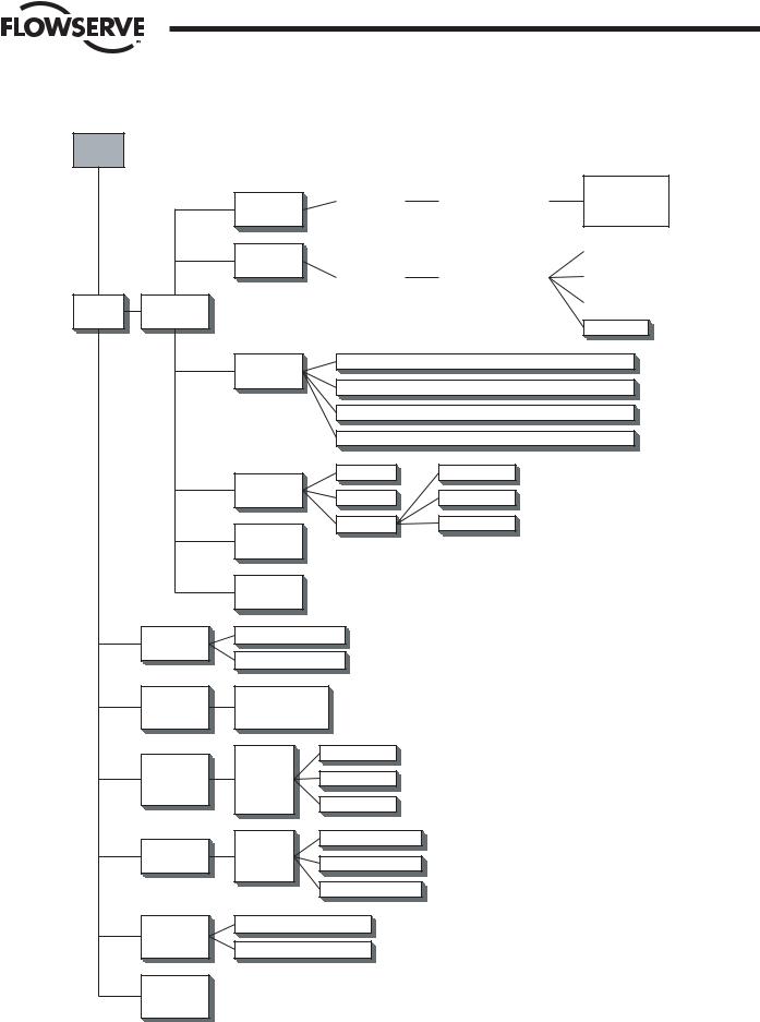
2Master Station II Screen Flowchart
Figure 2-1 (on the following page) is a flowchart of the Master Station II screens.
FCD LMAIM5001-00 |
DDC-100 Master Station II Installation and Operation Manual |
9 |
Flow Control Division
Limitorque Actuation Systems
Figure 2-1: Screen flowchart
Intro
Screen
Main |
Configure |
|
Menu |
||
|
MOV |
Network |
DCS Port |
Ethernet |
Port |
General |
Settings |
Change Tags |
|
Baud Rate |
|
Timeout |
|
|
|
|
|
|
|
|
|
|
|
|
||
|
Retries |
|
Prop Delay |
|
Active MOVs 1- |
|
|
|
|
Poll Mode |
|
RTS On Delay |
|
250 |
|
|
|
|
|
|
|
|
|
|
|
|
|
|
|
|
|
|
|
|
|
|
|
|
|
|
Modbus FC 03 - View |
|
||
|
Baud Rate |
|
DCS Port Address |
|
|
|
|
|
|
|
|
|
|
|
|
||
|
Stop Bits |
|
RTS On Delay |
|
Modbus FC 05/15 - View |
|||
|
Parity |
|
RTS Off Delay |
|
|
|
|
|
|
Electrical |
|
HMI Control |
|
Modbus FC 06/16 - View |
|||
|
|
|
|
|
|
|
|
|
HMI Control
IP Address - Octet 1 - Octet 2 - Octet 3 - Octet 4
Mask - Octet 1 - Octet 2 - Octet 3 - Octet 4
Gateway - Octet 1 - Octet 2 - Octet 3 - Octet 4
Standby IP Address - Octet 1 - Octet 2 - Octet 3 - Octet 4
Clock |
View |
Version |
Supervisor |
Password Administrator
Hot Standby |
Network |
Status |
View MOV
Status
Control MOV |
Emergency |
Shutdown |
Exit |
Save to
Flash
Change Status
Hot Backup Startup
Communication
Status
MOVs 1-250
MOV Stats Address 1- 250
Control MOVs 1-250
Position
Faults
Alarms
Open/Stop/Close
0-100% Open
Aux Contacts
Start Network ESD
Terminate Network ESD
10 |
DDC-100 Master Station II Installation and Operation Manual |
FCD LMAIM5001-00 |
Flow Control Division
Limitorque Actuation Systems
3Quick Startup
3.1Single Master Station Quick Setup Instructions
1.Connect power, earth ground, and network cables per Flowserve recommendations.
2.Turn power on to the Master Station.
3.Wait for the Master Station display to illuminate and the “Press Anywhere To Begin” message.
4.Press the screen and enter the configuration password when prompted. Select Enter.
5.Next select “Configure” then “MOV network”. Select the network baud rate, Time-out, retries, adjust the Propagation delay and RTS ON delay if required. Next activate the appropriate number of networked MOVs by making the lamp beside the address green.
6.Select the Back button until the Configuration screen is displayed.
7.From the Configure screen, select “DCS Port.” Select the desired baud rate, stop bits, parity and electrical standard. Select Next and configure the Master Station DCS port address, adjust the RTS ON Delay and RTS OFF Delay if required. Select Next for the “Configure DCS Data Table screen”.
8.Configure the data tables for the Master Station.
9.To create the Holding register data table (40000 register block for MOV status) for the Master Station, select Modbus Fc 03. Select the MOV registers to be available for the DCS by pressing the toggle switch to illuminate the “green light” on the switch. View the selections and save the changes and return to the “Configure DCS Data Table” screen.
10.To create the Coils data table (0000 register block for forcing and reading coils) for the Master Station, select Modbus Fc 05/15. Select the MOV Coils to be available for the DCS by pressing the toggle switch to illuminate the “green light” on the switch. Save the changes and return to the “Configure DCS Data Table” screen. Note this feature also creates the Modbus Fc 01 (Read Coils) data table.
11.To create the Holding register data table (45000 register block for writing holding registers) for the Master Station, select Modbus Fc 06/16. Select the number of write registers for the MOVs to be available for the DCS by pressing the toggle switch to illuminate the “green light” on the switch. View the selections and save the changes and return to the “Configure DCS Data Table screen.”
12.Select Back until reaching the “Configure” screen. Select Back and when prompted to Save, Select Yes.
13.This will permit a rapid configuration of the Master Station. Further adjustments may be made by following the procedures outlined in the Master Station Manual.
3.2Hot Standby Master Station Quick Setup Instructions
Connect power, earth ground, and network cables per Flowserve recommendations.
3.2.1Configure the Left CPU
1.Turn on power to the left processor of the Master Station. DO NOT apply power to the right half of the Master Station.
2.Wait for the Master Station display to illuminate and the “Press Anywhere To Continue” message.
3.Press the screen and enter the configuration password when prompted. Select Enter.
FCD LMAIM5001-00 |
DDC-100 Master Station II Installation and Operation Manual |
11 |

Flow Control Division
Limitorque Actuation Systems
4.From the Main Menu select Configure.
5.Select Ethernet Port.
6.Complete the setup of the IP address, mask, gateway, and standby address. Select Back from the Configure window. You will be prompted to Save. Select NO. The Blue window will disappear. Select Back and return to the Main Menu.
Left unit (default configuration): IP address: 192.168.0.100 Mask: 255.255.255.0
Gateway: 192.168.0.1
Hot Stby IP: 192.168.0.101
7.From the Main Menu select Hot Standby.
8.Set the Hot Backup Startup as Hot. Select Back.
9.You will be prompted to save the configuration. Select Yes.
10.When the save process is complete turn off the left unit.
3.2.2Configure the Right CPU
1.Turn on power to the right processor of the Master Station. DO NOT apply power to the left half of the Master Station.
2.Wait for the Master Station display to illuminate and the “Press Anywhere To Continue” message.
3.Press the screen and enter the configuration password when prompted. Select Enter.
4.From the Main Menu select Configure.
5.Select Ethernet Port.
6.Complete the setup of the IP address, mask, gateway, and standby address. Select Back from the Configure window. You will be prompted to Save. Select NO. The Blue window will disappear. Select Back and return to the Main Menu.
Note: The IP address is the standby address of the left processor AND the standby address is the IP address of the left processor.
Left |
Right |
IP |
IP |
Standby |
Standby |
Right unit (default configuration):
IP address: 192.168.0.101
Mask: 255.255.255.0
Gateway: 192.168.0.1
Hot Stby IP: 192.168.0.100
7.From the Main Menu select Hot Standby.
8.Set the Hot Backup Startup as Standby. Select Back.
9.You will be prompted to save the configuration. Select Yes.
10.When the save process is complete turn off the right unit.
3.2.3Configure the Master Station for network control
1.Apply power to the left and right CPUs. Wait for the Master Station display to illuminate and the “Press Anywhere To Continue” message to appear. One Master Station will display “Active” the other will display “Standby”.
12 |
DDC-100 Master Station II Installation and Operation Manual |
FCD LMAIM5001-00 |

Flow Control Division
Limitorque Actuation Systems
2.Press the screen of the ACTIVE Master Station and enter the configure password when prompted. Select Enter.
3.From the Main Menu, select Configure
4.Next select Configure the MOV network. Select the network baud rate, Time-out, retries, adjust the Propagation delay and RTS ON delay if required. Next activate the number of networked MOVs by making the button beside the address green.
5.Select the Back button until the Configuration screen is displayed.
6.Configure the data tables for the Master Station.
a.To create the Holding register data table (40000 register block for MOV status) for the Master Station, select Modbus Fc 03. Select the MOV registers to be available for the DCS by pressing the toggle switch to illuminate the “green light” on the switch. Save the changes and return to the “Configure DCS Data Table screen.”
b.To create the Coils data table (0000 register block for forcing and reading coils) for the Master Station, select Modbus Fc 05/15. Select the MOV Coils to be available for the DCS by pressing the toggle switch to illuminate the “green light” on the switch. Save the changes and return to the “Configure DCS Data Table” screen. Note this feature also creates the Modbus Fc 01 (Read Coils) data table.
c.To create the Holding register data table (45000 register block for writing holding registers) for the Master Station, select Modbus Fc 06/16. Select the number of write registers for the MOVs to be available for the DCS by pressing the toggle switch to illuminate the “green light” on the switch. Save the changes and return to the “Configure DCS Data Table screen.”
7.Select Back until reaching the “Configure” screen. Select Back and when prompted to Save, select Yes.
Note: All network configuration data, MOV data, and Master Station Data table configuration parameters will be automatically saved to the standby Master Station.
DCS Port configuration data will not be saved as these ports are independently configured.
Items NOT saved to the Standby Master Station:
DCS Address DCS Baud Rate
DCS Electrical Standard DCS Stop bits
DCS Parity
DCS RTS On Delay DCS RTS Off Delay
DCS Startup (Hot or Standby) IP Address
IP Mask Gateway
Standby IP Address
8.This will permit a rapid configuration of the Master Station. Further adjustments may be made by following the procedures outlined in the Master Station Manual.
FCD LMAIM5001-00 |
DDC-100 Master Station II Installation and Operation Manual |
13 |

Flow Control Division
Limitorque Actuation Systems
This page is intentionally blank.
14 |
DDC-100 Master Station II Installation and Operation Manual |
FCD LMAIM5001-00 |
Flow Control Division
Limitorque Actuation Systems
4Connections
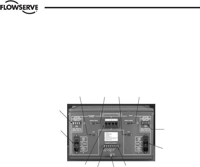
4.1 Master Station Rear Panel Connections
Figure 4-1: Master Station connections
11 |
12 |
3 |
2 |
10
9 |
4 |
5
1 |
8 |
7 |
6 |
|
|
1.Ethernet Ports, RJ-45 connectors. One port is designated for MNET (Modbus Ethernet TCP/IP). The other port is for the webserver. Either port may be used for either function as they are connected to the same CPU.
2.Printer / Debug Port. DB-9 Female connector. RS-232 port. Used for Master Station diagnostics.
FCD LMAIM5001-00 |
DDC-100 Master Station II Installation and Operation Manual |
15 |
Flow Control Division
Limitorque Actuation Systems
Figure 4-2: Debug Port Connection
RS 232
DB-9
DSR
6
DTR
4
RTS
7
RXD
2
DCD
1
CTS
8
TXD
3
GND
5
9N/C
3.DCS Port. DB-9 Female connector. Port may be RS-232 or RS-422 or RS-485. Each electrical standard uses a different wiring convention.
Figure 4-3: DCS Port Connection
RS 232 |
RS 485 |
RS 422 |
DB-9
DSR |
|
RXD- |
6 |
|
|
DTR |
|
|
4 |
|
|
RTS |
|
|
7 |
|
|
RXD |
|
RXD+ |
2 |
|
|
DCD |
TXRXD+ |
TXD+ |
1 |
|
|
CTS |
TXRXD- |
TXD- |
8 |
|
|
TXD |
|
|
3 |
|
|
GND |
GND |
GND |
5 |
|
|
9N/C
4.Auxiliary 24 VDC power connection. Master Station may be configured for 24 VDC power. This will require the jumpers inside the Master Station to be configured for 24 VDC. DO NOT use 120 VAC when using
24 VDC power.
5.Main power switch and connector for 120 – 240 VAC. DO NOT use when 24 VDC power is applied.
16 |
DDC-100 Master Station II Installation and Operation Manual |
FCD LMAIM5001-00 |

Flow Control Division
Limitorque Actuation Systems
Table 4-1: Network Channel B Connection
Connector |
MX-DDC |
UEC-3-DDC |
Data |
41 |
TB4 D-S |
Data * |
29 |
TB4 D-S* |
Shield |
|
|
6.Electrostatic Ground. A good quality earth ground MUST be attached to the Master Station. An effective local, low-impedance earth ground (less than 5 ohms) is required.
Table 4-2: Network Channel A Connection
Connector |
MX-DDC |
UEC-3-DDC |
Data |
16 |
TB3 D-M |
Data * |
15 |
TB3 D-M* |
Shield |
|
|
7.Hot Standby unit main power switch and connector for 120 – 240 VAC. DO NOT use when 24 VDC power is applied.
8.Hot Standby auxiliary 24 VDC power connection. Master Station may be configured for 24 VDC power. This will require the jumpers inside the Master Station to be configured for 24 VDC. DO NOT use 120 VAC when using 24 VDC power.
9.Hot Standby DCS Port. DB-9 Female connector. Port may be RS-232 or RS-422 or RS-485. Each electrical standard uses a different wiring convention.
10.Hot Standby Printer / Debug Port. DB-9 Female connector. RS-232 port. Used for Master Station diagnostics.
4.2Master Station Wiring Requirements
The network cable connects the field units to the host controller or Master Station. Belden 3074F, 3105A, or 9841 shielded, twisted-pair cable should be used. The use of other cables may result in a reduction of internodal distances or increased error rate, and is the user’s responsibility.
Belden 3074F Specifications
• Total cable length between repeaters or nodes with repeaters: up to 19.2 kbps: 5000' (1.52 km)
For loop mode, this is the total length between operating field units. If a field unit loses power, the relays internal to the field unit connect the A1 Channel to the A2 Channel, which effectively doubles the length of the cable (assuming a single field unit fails). To ensure operation within specifications in the event of power failure to field units, this consideration must be added. Example: To ensure operation within specification when any two consecutive field units lose power, the maximum length of cable up to 19.2 bkps should not exceed 5000' (1.52 km) per every four field units. See Section 3.1.2.3, Network Cable Connection to Host Controller or Master Station.
Key Specifications
•Resistance/1000 ft = 18 AWG (7 x 26) 6.92 ohms each conductor (13.84 ohms for the pair)
•Capacitance/ft = 14 pF (conductor-to-conductor)
•Capacitance/ft = 14 pF (conductor-to-shield)
FCD LMAIM5001-00 |
DDC-100 Master Station II Installation and Operation Manual |
17 |

Flow Control Division
Limitorque Actuation Systems
Belden 3105A Specifications
• Total cable length between repeaters or nodes with repeaters: up to 19.2 kbps: 4500' (1.37 km)
For loop mode, this is the total length between operating field units. If a field unit loses power, the relays internal to the field unit connect the A1 Channel to the A2 Channel, which effectively doubles the length of the cable (assuming a single field unit fails). To ensure operation within specifications in the event of power failure to field units, this consideration must be added. Example: To ensure operation within specification when any two consecutive field units lose power, the maximum length of cable up to 19.2 bkps should not exceed 4500' (1.37 km) per every four field units. See Section 3.1.2.3, Network Cable Connection to Host Controller or Master Station.
Key Specifications
•Resistance/1000 ft = 22 AWG (7 x 30) 14.7 ohms each conductor (29.4 ohms for the pair)
•Capacitance/ft = 11.0 pF (conductor-to-conductor)
•Capacitance/ft = 20.0 pF (conductor-to-shield)
Belden 9841 Specifications
• Total cable length between repeaters or nodes with repeaters: up to 19.2 kbps: 3500' (1 km)
For loop mode, this is the total length between operating field units. If a field unit loses power, the relays internal to the field unit connect the A1 Channel to the A2 Channel, which effectively doubles the length of the cable (assuming a single field unit fails). To ensure operation within specifications in the event of power failure to field units, this consideration must be added. Example: To ensure operation within specification when any two consecutive field units lose power, the maximum length of cable up to 19.2 bkps should not exceed 3500' (1 km) per every four field units. See Section 3.1.2.3, Network Cable Connection to Host Controller or Master Station.
Key Specifications
•Resistance/1000 ft = 24 AWG (7 x 32) 24 ohms each conductor (48 ohms for the pair)
•Capacitance/ft = 12.8 pF (conductor-to-conductor)
•Capacitance/ft = 23 pF (conductor-to-shield)
18 |
DDC-100 Master Station II Installation and Operation Manual |
FCD LMAIM5001-00 |

Flow Control Division
Limitorque Actuation Systems
4.3Master Station Network Schematic
Figure 4-4: DDC-100 Redundant Loop Network
Diagnostic Note:
Polarity and level of the network’s data connection can be checked by measuring voltage between data and data* terminals. This voltage should be greater than +200mVDC with network controller network ports disconnected.
Earth Ground Note:
If low impedance earth ground is not available at each actuator, contact engineering for alternative earth ground surge protection strategies.
MASTER STATION II |
|
|
Channel A |
Legend |
|
Channel B |
Motor-Operated Valve |
|
|
MOV |
|
|
16 |
Data A1 |
|
15 |
Data A1* |
|
41 |
Data A2 |
|
29 |
Data A2* |
|
D-M |
Data A1 (UEC-3-DDC) |
|
D-M* |
Data A1*(UEC-3-DDC) |
|
D-S |
Data A2 (UEC-3-DDC) |
|
D-S* |
Data A2* (UEC-3-DDC) |
|
|
Shield |
|
N/C |
No Connection |
Data terminal is positive with respect to data* terminal
|
|
|
|
|
|
MOV-2 |
|
|
|
|
|
|
|
|
|
MOV-4 |
|
|
||
|
MOV-1 |
|
|
|
|
See Note 5 |
|
|
|
MOV-3 |
|
|
|
|
See Note |
5 |
|
|||
|
|
|
|
|
|
|
|
|
|
|
|
|
|
|
|
|
|
|||
|
TB3 |
TB4 |
|
N/C |
|
|
|
|
|
|
TB3 |
|
TB4 |
|
N/C |
|
|
|
|
N/C |
A1 |
A2 |
|
A1* 15 |
|
|
A1 |
|
A2 |
|
A1* 15 |
|
|
||||||||
D-M |
D-S |
|
|
|
|
D-M |
|
D-S |
|
|
|
|
||||||||
A1* |
A2* |
|
|
A1 |
16 |
|
|
A1* |
|
A2* |
|
|
A1 |
16 |
|
|
||||
D-M* |
D-S* |
|
|
|
|
D-M* |
|
D-S* |
|
|
|
|
||||||||
|
|
|
|
29 |
A2* |
|
|
|
|
|
|
|
29 |
A2* |
|
|
||||
|
|
|
|
|
|
|
N/C |
|
|
|
|
|
|
|
|
|
||||
|
|
|
|
|
|
41 |
A2 |
|
|
|
|
|
|
|
|
41 |
A2 |
|
|
|
|
|
|
|
|
|
|
|
|
|
|
|
|
|
|
|
|
||||
|
TB5 |
|
|
|
|
|
|
|
|
|
|
TB5 |
|
|
|
|
|
|
|
|
|
See Note 5 |
|
|
|
|
|
|
|
|
See Note |
5 |
|
|
|
|
|
|
|
||
|
MOV-250 |
|
|
|
|
|
|
|
|
MOV-248 |
|
|
|
|
|
|
|
|
||
|
See Note 5 |
|
|
|
MOV-249 |
|
|
|
See Note |
5 |
|
|
|
MOV-247 |
|
|
||||
|
|
|
|
|
|
|
|
|
|
|
|
|
|
|
|
|
||||
|
|
|
|
N/ C |
|
TB4 |
TB3 |
|
|
|
A1* 15 |
|
|
N/C |
|
TB4 |
|
TB3 |
|
|
|
A1* |
15 |
|
|
A2 |
A1 |
|
|
|
|
|
A2 |
|
A1 |
||||||
|
|
|
D-S |
D-M |
|
|
|
|
|
D-S |
|
D-M |
||||||||
|
A1 |
16 |
|
|
A2* |
A1* |
|
|
A1 |
16 |
|
|
|
A2* |
|
A1* |
||||
|
|
|
D-S* |
D-M* |
|
|
|
|
|
D-S* |
|
D-M* |
||||||||
|
29 |
A2* |
|
|
|
|
|
|
29 |
A2* |
|
|
|
|
|
|
||||
|
|
|
|
|
|
|
N/C |
|
|
|
|
|
|
|
|
|
||||
|
41 |
A2 |
|
|
|
|
|
|
|
41 |
A2 |
|
|
|
|
|
|
|
|
|
|
|
|
|
|
|
|
TB5 |
|
|
|
|
|
|
|
|
|
|
TB5 |
|
|
|
|
|
|
|
|
See Note 5 |
|
|
|
|
|
|
|
|
|
See Note |
5 |
|
||
Notes:
1)Belden 3074F, 3105A, or 9841 shielded cable is recommended.
2)Correct polarity for field unit and network controller connection is necessary for proper operation.
3)Connections shown are typical. The number of MOVs shown may not indicate true system size.
4)Earth ground: ground rod
5)Earth ground: ground rod or lug in actuator if actuator is grounded.
FCD LMAIM5001-00 |
DDC-100 Master Station II Installation and Operation Manual |
19 |

Flow Control Division
Limitorque Actuation Systems
This page is intentionally blank.
20 |
DDC-100 Master Station II Installation and Operation Manual |
FCD LMAIM5001-00 |
5
FCD LMAIM5001-00
Flow Control Division
Limitorque Actuation Systems
Configuration
5.1Login
From the Main Menu, touching the Configure button will prompt for the Configure password if the user is not already logged in as the Configure user (Figure 5-1). This screen will not be displayed if the initial password entered is the configure password.
Figure 5-1: The Configure Password screen
Login: Enter Configuration Password
**** |
||
7 |
8 |
9 |
4 |
5 |
6 |
1 |
2 |
3 |
<< Back |
0 |
|
|
|
|
DEL |
CLR |
E |
N |
T |
5.2Configure Main Screen
After successfully logging in as the Configure user, the Configure main screen will be presented (Figure 5-2).
DDC-100 Master Station II Installation and Operation Manual |
21 |
Flow Control Division
Limitorque Actuation Systems
Figure 5-2: The Configure main screen
Configure |
ACTIVE |
MOV
DCS Port
Network
Ethernet |
General |
Port |
Settings |
Save Config
Change Tags
to Flash
<< Back
The Configure main screen allows the user to configure five areas of the Master Station:
MOV Network: includes baud rate for network, retries, poll mode, timeout, propagation delay, RTS ON delay, and screens to allow the user to graphically select the active MOVs.
DCS Port: includes baud rate for DCS communication, stop bits, parity, electrical standard, DCS address, RTS ON delay, RTS OFF delay, HMI state during DCS communication traffic, and selectable register maps for Modbus function code 3, Modbus function code 5/15, and Modbus function code 6/16.
Ethernet Port: includes IP Address, Mask, Gateway, and Hot Standby IP Address. General Settings: includes Clock, Passwords, and Version information.
Hot Standby: includes buttons for forcing a state switch from Hot to Standby or Standby to Hot, indicates the current state, and the Hot Backup Startup state.
Note: CONFIGURATION CHANGES WILL BE LOST UNLESS SAVED TO FLASH. It is important that desired configuration changes are saved to flash by pushing the green “Save Config to Flash” button before exiting. Attempting to exit without saving will cause a prompt to save changes.
Figure 5-3: Confirmation to Change configuration screen
Configuration Changed
Do you wish to save changes made to this configuration?
Yes |
No |
22 |
DDC-100 Master Station II Installation and Operation Manual |
FCD LMAIM5001-00 |

Flow Control Division
Limitorque Actuation Systems
Figure 5-4: Saving Changes to Flash screen
Please Wait
Please wait while the configuration is saved to flash.
This operation requires approximately 20 seconds.
Figure 5-5: Configuration Not Changed screen
Configuration Not Changed
There have been no changes made to the configuration.
OK
FCD LMAIM5001-00 |
DDC-100 Master Station II Installation and Operation Manual |
23 |
Flow Control Division
Limitorque Actuation Systems
5.3Change Tags
Each MOV has a Tag name associated with it to provide a user-friendly identification. These tags can be edited by the user via the Change Tags screen (Figure 5-6).
Figure 5-6: Change Tag Name screen
Change Tag Name |
|
|
|
-10 |
MOV Address |
1 |
+10 |
|
|
||
|
Character - |
|
|
Pos - |
Tag Value |
|
Pos + |
|
M O V F U 0 0 1 |
|
|
|
Character + |
|
|
<< Back |
|
|
Save Tag |
|
|
|
|
The MOV Address indicates the MOV currently being edited. The arrows to the left and right of the MOV Address allow the user to navigate between MOVs. The +10 and -10 buttons allow the user to rapidly skip between MOVs.
In the center of the screen the MOV tag name is displayed. The Pos and Pos arrows allow the user to edit different characters in the tag name. The Character + and Character - arrows allow the user to increase a character, for example A to B to C or to decrease a character, C to B to A. In this manner, the user may rapidly create custom tags for each MOV.
It is important to touch the “Save Tag” button before the user edits a different MOV or exits the screen. “Save Tag” must be touched for each tag changed. Failing to touch “Save Tag” will result in loss of data.
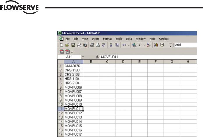
5.3.1Altering Tag Names with Microsoft Excel
1.Attach a PC to the Master Station Ethernet port. Configure the PC Ethernet port to communicate with the Master Station.
Example: |
|
|
|
|
|
|
|
|
|
Master Station |
PC |
|
IP |
192.168.0.100 |
192.168.0.101 |
|
Mask |
255.255.255.0 |
255.255.255.0 |
|
Gateway |
192.168.0.1 |
192.168.0.1 |
|
Standby IP |
0.0.0.0 |
0.0.0.0 |
2.Copy the TAGNAME file to a PC using a FTP (File Transfer Protocol).
3.Open the TAGNAME file with Excel.
4.Column A will contain 250 rows corresponding to the 250 allowable addresses for the Master Station.
5.Example Row 1 is MOV Address 1, Row 2 is MOV Address 2, etc.
6.Edit the tag name for each address.
7.The Master Station supports the ASCII character set.
24 |
DDC-100 Master Station II Installation and Operation Manual |
FCD LMAIM5001-00 |
Flow Control Division
Limitorque Actuation Systems
8.Tag names are limited to 8 characters. Spaces and other symbols are considered a character.
9.Save the file in .CSV (comma separated value) format.
10.Using FTP, copy the TAGNAME file to the Active Master Station.
11.Power cycle the Master Station to load the new TAGNAME file. On power-up the new tag names will appear on the ACTIVE Master Station.
12.For a Hot Standby Master Station, after the Active unit has been power cycled, enter the configuration screens and save the current configuration. This will transfer the new TAGNAME file to the Standby Master Station.
FCD LMAIM5001-00 |
DDC-100 Master Station II Installation and Operation Manual |
25 |

Flow Control Division
Limitorque Actuation Systems
This page is intentionally blank.
26 |
DDC-100 Master Station II Installation and Operation Manual |
FCD LMAIM5001-00 |
Flow Control Division
Limitorque Actuation Systems
6MOV Network Configuration
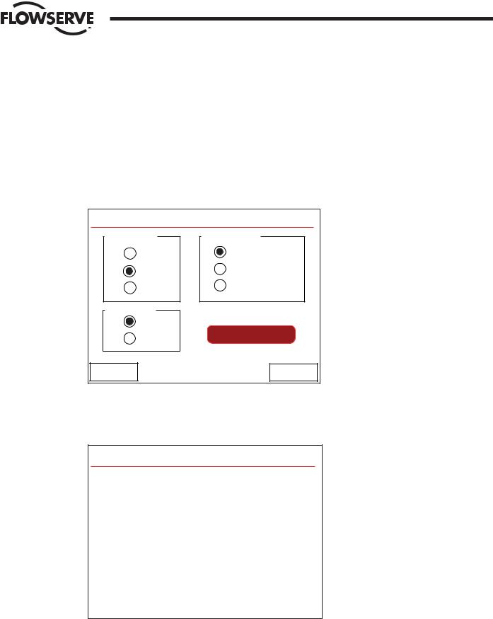
These screens allow the user to configure the MOV network for operation. The first screen presented allows the user to configure Baud Rate, Retries, and Poll Mode (Figure 6-1).
Figure 6-1: The Configure MOV Network screen
Configure MOV Network
Baud Rate |
Poll Mode |
4800 |
Redund. Loop |
9600 |
A Port Only |
19200 |
B Port Only |
Retries |
|
1 |
|
2 |
Auto Search |
|
|
<< Back |
Next >> |
Once these parameters are configured, the “Auto Search” button can be pressed. This will cause the Master Station to poll the network, searching for active MOVs. All inactive MOVs will be disabled in its configuration (Figure 6-2).
Figure 6-2: Auto-configuring Network screen
Auto-Configuring Network
The Network is being auto-configured.
This process can take several minutes.
Please wait.
Estimated Time Remaining: # minutes
Touching “Next >>” will take the user to the next configuration screen on which the Timeout, First Active MOV, Last Active MOV, Total MOVs, Propagation Delay, and RTS ON Delay can be configured (Figure 6-3).
FCD LMAIM5001-00 |
DDC-100 Master Station II Installation and Operation Manual |
27 |
 Loading...