


Worcester Actuation Systems
FCD WCAIM2037-00
(Part 17522)
DataFlo Digital Electronic Positioner DFP17
Installation, Operation and Maintenance Instructions
MODELS:
10 - For DataFlo Boards Mounted Inside 10-23 75 Actuators.
25 - For DataFlo Boards Mounted Inside 25/30 75 Actuators.
Inputs: |
|
|
DFP17 - 1K |
(120A, 240A, 24D) |
1000 ohm Input |
DFP17 - 13 |
(120A, 240A, 24D) |
135 ohm Input |
DFP17 - 1 |
(120A, 240A, 24D) |
1 to 5 milliamp Input |
DFP17 - 4 |
(120A, 240A, 24D) |
4 to 20 milliamp Input |
DFP17 - 10 |
(120A, 240A, 24D) |
10 to 50 milliamp Input |
DFP17 - 5V (120A, 240A, 24D) |
0 to 5 VDC Input |
|
DFP17 - XV (120A, 240A, 24D) |
0 to 10 VDC Input |
|
Voltages: |
|
|
120A - 120 VAC Power Circuits |
|
|
240A - 240 VAC Power Circuits |
|
|
24D - 24 VDC Power Circuits |
|
|

|
|
|
Flow Control |
|
|
|
|
|
|
|
|
Worcester Actuation Systems |
||
TABLE OF CONTENTS |
|
|
||
1.0 GENERAL |
Page |
|||
4 |
|
|||
1.1 |
Basic Design |
5 |
|
|
1.2 |
Environmental Considerations |
5 |
|
|
|
1.2.1 Temperature |
5 |
|
|
|
1.2.2 Humidity |
5 |
|
|
|
1.2.3 Input Circuit Noise Protection |
5 |
|
|
2.0 DataFlo ELECTRONIC POSITIONER CIRCUIT BOARD |
8 |
|
||
2.1 |
General |
8 |
|
|
2.2 |
Circuit Board Configurations |
8 |
|
|
2.3 |
LED Indicators |
8 |
|
|
2.4 |
Controls (Override) |
8 |
|
|
2.5 |
AC Power Control |
8 |
|
|
3.0 WIRING OF DIGITAL CONTROLLER AND SERIES 75 ELECTRIC ACTUATOR |
8 |
|
||
3.1 |
Actuator Power |
8 |
|
|
|
3.1.1 Wire Size |
8 |
|
|
|
3.1.2 Termination and Voltage |
8 |
|
|
|
3.1.3 Minimum Fuse Ratings |
8 |
|
|
3.2 |
Input Signal Connections |
9 |
|
|
|
3.2.1 Milliamp |
9 |
|
|
|
3.2.2 Resistive |
9 |
|
|
|
3.2.3 DC Voltage |
9 |
|
|
4.0 CALIBRATION AND ADJUSTMENT |
12 |
|
||
4.1 |
DataFlo Calibration Procedures, Initial Setup and Adjustment (Applies to all Models) |
12 |
|
|
|
4.1.1 Calibration Procedures for Microchip U5 or U3 Rev. V2.12 and Newer |
12 |
|
|
|
4.1.2 Calibration Procedures for Microchip U5 or U3 Rev. V2.11 and Older |
12 |
|
|
|
4.1.3 Initial Setup and Adjustments |
13 |
|
|
4.2 |
General Description of Digital Positioner |
13 |
|
|
|
4.2.1 Valve Position Setpoint Input |
13 |
|
|
|
4.2.2 Valve Position Feedback |
13 |
|
|
|
4.2.3 Key Features of the Digital Positioner |
13 |
|
|
|
4.2.4 Operating Modes |
14 |
|
|
|
4.2.5 Data Readout |
14 |
|
|
|
4.2.6 Local Data Entry |
14 |
|
|
|
4.2.7 Display Modes |
14 |
|
|
4.3 |
Program Mode |
14 |
|
|
|
4.3.1 Security Code Screen |
14 |
|
|
|
4.3.2 Unit Address Screen |
15 |
|
|
|
4.3.3 Output Current Range |
15 |
|
|
|
4.3.4 Analog Setpoint (Input) Range |
15 |
|
|
|
4.3.5 Setpoint Direction - Direct-Acting (Rise), Reverse-Acting (Fall) |
15 |
|
|
|
4.3.6 Setpoint Split Range START Selection |
15 |
|
|
|
4.3.7 Setpoint Split Range END Selection |
15 |
|
|
|
4.3.8 Setpoint Ramp - Time to Open |
15 |
|
|
|
4.3.9 Setpoint Ramp - Time to Close |
15 |
|
|
|
4.3.10 Setpoint Curve Function |
16 |
|
|
|
4.3.11 Positioner Deadband |
16 |
|
|
|
4.3.12 Loss of Signal Position and Delay Time |
16 |
|
|
2 |
DataFlo Digital Electronic Positioner DFP17 Installation, Operation and Maintenance Instructions |
WCAIM2037 |
||

|
|
|
|
Flow Control |
|
|
|
|
|
|
|
|
|
|
Worcester Actuation Systems |
||
|
|
4.3.13 Power-On Position and Delay Time |
16 |
|
|
|
|
4.3.14 Electronic Positioner Rotation Limits (Electronic Travel Stops) |
17 |
|
|
|
|
4.3.15 Tight Valve Shutoff |
17 |
|
|
|
|
4.3.16 Full Open Operation of Valve with Open Travel Limit Set |
17 |
|
|
|
|
4.3.17 Brake On Time |
17 |
|
|
|
|
4.3.18 Restore Factory Default Values |
17 |
|
|
|
|
4.3.19 Run Time Cycles for Maintenance |
17 |
|
|
|
|
4.3.20 Alarm Functions |
17 |
|
|
4.4 |
Local Mode |
18 |
|
||
4.5 |
Feedback Calibration Routine and Cycle Time Measurement |
18 |
|
||
|
|
4.5.1 For Microchip U5 or U3 Rev. V2.12 and Newer |
18 |
|
|
|
|
4.5.2 For Microchip U5 or U3 Rev. V2.11 and Older |
19 |
|
|
4.6 |
Run Mode |
20 |
|
||
|
|
4.6.1 Valve Position Screen |
20 |
|
|
|
|
4.6.2 Input Setpoint |
20 |
|
|
|
|
4.6.3 Cycle Count |
20 |
|
|
|
|
4.6.4 Deadband Readout |
20 |
|
|
|
|
4.6.5 CW and CCW Travel Time Readout |
20 |
|
|
|
|
4.6.6 Alarm Status Readout |
20 |
|
|
|
|
4.6.7 Changing Operating Modes |
21 |
|
|
4.7 |
Default Values (Factory Installed) |
21 |
|
||
4.8 |
Calibrating and Programming the Digital Positioner |
22 |
|
||
|
|
4.8.1 Programming Switches |
22 |
|
|
|
|
4.8.2 Programming the Positioner Board |
22 |
|
|
|
|
4.8.3 Programming the FrE1, FrE2, FrE3, and FrE4 Curves |
22 |
|
|
4.9 |
RS-485 Communications |
22 |
|
||
|
|
4.9.1 Packet Communications Software |
23 |
|
|
|
|
4.9.2 RS-485 Connection |
23 |
|
|
|
|
4.9.3 Communications Software |
23 |
|
|
|
|
4.9.4 Serial Port Setup |
23 |
|
|
|
|
4.9.5 Monitor Display |
23 |
|
|
5.0 TECHNICAL DATA |
26 |
|
|||
5.1 |
Allowable Supply Voltage Range |
26 |
|
||
5.2 |
Input Circuit Specifications |
26 |
|
||
5.3 |
Output Circuit Specifications |
26 |
|
||
5.4 |
Input Circuit Load Resistances |
26 |
|
||
6.0 APPLICATION NOTES |
27 |
|
|||
6.1 |
Bypass Switch for Manual Control (For 120 VAC Only) |
27 |
|
||
7.0 TROUBLESHOOTING |
28 |
|
|||
7.1 |
General |
28 |
|
||
|
|
7.1.1 Cam Adjustment |
28 |
|
|
|
|
7.1.2 Check Fuse F1 |
28 |
|
|
|
|
7.1.3 Check Basic Actuator for Proper Operation |
28 |
|
|
|
|
7.1.4 Check for Noise Problems |
28 |
|
|
|
|
7.1.5 Replace Circuit Board |
28 |
|
|
7.2 |
Symptom Table |
29 |
|
||
7.3 |
Troubleshooting Guidelines |
30 |
|
||
WCAIM2037 |
|
DataFlo Digital Electronic Positioner DFP17 Installation, Operation and Maintenance Instructions |
3 |
||
Flow Control
1.0GENERAL
1.1Basic Design
The Worcester/McCANNA DataFlo Digital Electronic Positioner (DFP17) was designed for use with the Worcester/McCANNA Series 75 electric actuators. However, it may also be used with other actuators or electrically operated rotary devices, provided the specified load parameters as given in Section 5.3 are not exceeded.
aCAUTION: This positioner is sensitive to electrical noise; please see Section 1.2.
Worcester Actuation Systems
referenced to the circuit board ground. This is especially important with DC powered circuit boards. The board power source must have a ground independent from that of the signal source.
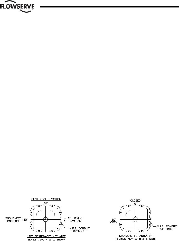
C.The Digital Positioner board can be set up in several ways for normal operation. The board is designed to control in 90˚ quadrants only (with alternate potentiometer gearing, 180˚ of rotation is available). The number of quadrants over which the board will control is determined by the number of teeth on the feedback pot pinion gear.
The standard setup is 4 mA for full clockwise rotation - i.e., 0˚ and 20 mA for full counter-clockwise Rotation - i.e., 90˚ or 180˚.
PLEASE READ THIS SECTION
A.The 4–20 mA signal input circuit of both the AC and DC Digital Positioner board is protected with a 62 mA fuse (F1). The fuse is used to protect the input circuit from an excessively high voltage. The fuse used in the input circuit is a Littlefuse PICO II very fast acting fuse rated at 62 mA.
All DC Digital Positioner boards also use a standard 11/4", 250 V, 3 A fuse (F2) to protect the circuit board and the power source in case of a fault in the DC motor driver integrated circuit on the circuit board.
a CAUTION: It is important that the DC voltage power source be properly connected to the actuator’s terminal strip. Terminal one (1) of this strip is to have the negative or common wire connected to it. Terminal two (2) is to have the positive wire connected to it.
NOTE: All wiring to terminal strip should be inserted only to the midpoint of terminal strip.
B.The Digital Positioner board is designed to receive a floating current input signal. This allows several pieces of equipment to be operated from the same current loop while at the same time remaining electrically independent of each other. A floating input signal means that the current input signal should not be
D.Quite often when we receive an actuator for repair, we find that the only thing wrong with the unit is that the feedback potentiometer is out of calibration. It is very important that the feedback pot be properly calibrated for correct operation of the positioner board. It is also very important that the actuator shaft not be rotated out of the quadrant for which the feedback pot has been calibrated. Whenever you have a problem with the positioner calibration, always check the feedback pot calibration first. This must be done with no power applied to the circuit board. If the actuator is in the full clockwise position, check the resistance between the purple and white/black potentiometer leads. The reading should be 80-90 ohms. If it is not, rotate the face gear until the proper reading is achieved. If the actuator happens to be in the full counter-clockwise position then check the resistance between the green and white/black potentiometer leads. If necessary adjust the face gear for an 80-90 ohm reading.
NOTE: It is not necessary to loosen or remove face gear snap ring(s) (if present) to rotate gear, it is a friction fit. For gears that do have snap rings, and if for any reason the snap ring(s) are to be removed, do not over stretch them; use the minimum opening to allow them to slip over the gear.
Figure 1 – Quadrants of Operation
4 |
DataFlo Digital Electronic Positioner DFP17 Installation, Operation and Maintenance Instructions |
WCAIM2037 |

Flow Control
Worcester Actuation Systems
1.2 Environmental Considerations |
1.2.2 Humidity |
aCAUTION: The DataFlo Digital Electronic Positioner is sensitive to electrical noise on signal or supply lines and in the environment. For maximum positioner sensitivity, the electrical noise level should be as low as possible. Follow installation, calibration and adjustment guidelines carefully and use shielded wire as stated in section 1.2.3.
Flowserve recommends that all products which must be stored prior to installation, be stored indoors, in an environment suitable for human occupancy. Do not store product in areas where exposure to relative humidity above 85%, acid or alkali fumes, radiation above normal background, ultraviolet light, or temperatures above 120˚F or below 40˚F may occur. Do not store within 50 feet of any source of ozone.
Temperature and humidity are the two most important factors that determine the usefulness and life of electronic equipment.
1.2.1Temperature
Operating solid state electronic equipment near or beyond its high temperature ratings is the primary cause for most failures. It is, therefore, very important that the user be aware of and take into consideration, factors that affect the temperature at which the electronic circuits will operate.
Operating an electronic device at or below its low temperature rating generally results in a unit operating poorly or not at all, but it will usually resume normal operation as soon as rated operating temperatures are reached. Low temperature problems can be easily cured by addition of a thermostatically controlled heater to the unit’s housing.
The Worcester/McCANNA DataFlo Digital Electronic Positioner is rated for operation between -40˚F (with heater and thermostat) and 160˚F. When using the Positioner inside the Worcester/McCANNA 75 Series actuators, a maximum ambient temperature of 115˚F is required to ensure the circuit board maximum temperature of 160˚F is not exceeded.
Most electronic equipment has a reasonable degree of inherent humidity protection and additional protection is supplied by the manufacturer, in the form of moisture proofing and fungicidal coatings.
Such protection, and the 3 to 4 watts of heat generated by the circuit board assembly will generally suffice for environments where the average relative humidity is in the area of 80% or less and ambient temperatures are in the order of 70˚F average.
Where relative humidity is consistently 80 to 90% and the ambient temperature is subject to large variations, consideration should be given to installing a heater and thermostat option in the enclosure. The heater should not increase the enclosure temperature to the point where the circuit board assembly’s temperature rating of 160˚F is exceeded.
In those instances where the internal heater would bring the circuit board operating temperature near or above its maximum rating, the user might consider purging the enclosure with a cool, dry gas. The initial costs can usually be paid off quickly in the form of greatly extended equipment life, low maintenance needs, and much less process downtime.
1.2.3Input Circuit Noise Protection
Shielded wiring should be used for all signal input circuit wiring regardless of length.
With separately housed positioners, the wiring from the feedback potentiometer to remote positioner, would be considered as signal input wiring and should also be shielded wire.
The shields should never be used in place of one of the input wires, and the shields should be grounded to equipment housings at one end of the wiring run only. Grounding both ends of shielding can eliminate the shielding benefits because of current ground loops. If two or more shielded cables come to the positioner from different locations, ground the shields at the positioner.
WCAIM2037 |
DataFlo Digital Electronic Positioner DFP17 Installation, Operation and Maintenance Instructions |
5 |
Flow Control
Worcester Actuation Systems
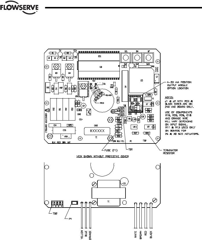
Figure 2 – Digital Electronic Positioner Circuit Board
120/240 VAC
6 |
DataFlo Digital Electronic Positioner DFP17 Installation, Operation and Maintenance Instructions |
WCAIM2037 |
Flow Control
Worcester Actuation Systems
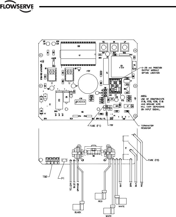
Figure 2 – Digital Electronic Positioner Circuit Board (continued)
24 VDC
WCAIM2037 |
DataFlo Digital Electronic Positioner DFP17 Installation, Operation and Maintenance Instructions |
7 |

Flow Control
Worcester Actuation Systems
2.0DataFlo ELECTRONIC POSITIONER CIRCUIT BOARD
2.1General
Figure 2 defines the location of major components and wires from the Positioner Board to terminal strip connections. The Digital Positioner Board is factory wired to the terminal strip either per Figure 4, Figure 5, Figure 6 or Figure 7, as found in Section 3.0, depending on power circuit voltage and if 4–20mA position output option is installed.
The feedback potentiometer leads are factory connected to the terminal block (TB1) on the Digital Positioner Board.
If a dual pot option is installed, the “B” pot leads will have to be wired directly to external device. The “A” pot leads are factory connected to the terminal block (TB1) on the Digital Positioner Board. Also, note that the “B” pot has a voltage limit of 30 volts maximum.
2.2 Circuit Board Configurations
The positioner board is factory supplied for one of the seven input signal options plus a two-wire RS-485 interface.
NOTE: Field changes to the positioner board are not advised. Consult Flowserve before attempting any modification.
2.3 LED Indicators
Light emitting diodes (LEDs) marked LD1 (CW) and LD2 (CCW) are in the output circuits and, when lit, indicate which direction the actuator is trying to drive. A third LED, LD3, is used to indicate when an alarm condition exists. If LD3 is lit, the alarm that caused it to light must be determined by looking at the Liquid Crystal Display (LCD) and finding the alarm parameter with the UP or DN switch.
2.4 Controls (Override)
There are no adjustable controls provided on the circuit board, because none are necessary. All parameters are set through the programming switches (keys) or the RS485 interface. Local pushbutton control is provided at the actuator by simultaneously pressing the SEL and UP switches (keys) for three seconds. At this point the UP and the DN switches (keys) can be used to manually position the actuator shaft. Pressing the SEL switch for three seconds will return the positioner to the run mode.
2.5 AC Power Control
The AC output circuits are controlled by solid state switches (triacs Q3, Q4), which will provide trouble-free operation for the life of the equipment they are used with, AS LONG AS THEY ARE OPERATED WITHIN THEIR RATINGS.
The ratings for the solid state switches used in the Worcester/ McCANNA DataFlo Digital Electronic Positioner are listed in Section 5.3.
3.0WIRING OF DIGITAL POSITIONER AND SERIES 75 ELECTRIC ACTUATOR
See wiring diagrams located under actuator cover and/or in Figures 4 through 7 for customer connections.
3.1 Actuator Power
aCAUTION: Wiring should be inserted only to midpoint of terminal strip.
3.1.1Wire Size
Power to the positioner and from the positioner to the actuator should be with wire no smaller than 18 gauge and with insulation rated for the particular application. The 18 gauge wire size is sufficient for all Worcester/ McCANNA Series 75 actuators. When using the Positioner with other makes of actuators, check the manufacturer’s current rating to determine the correct wire size.
3.1.2Termination and Voltage
Power connections are made to terminals 1 and 2 of the terminal strip. The AC neutral or common, or DC negative wire should be connected to terminal #1 and the AC “hot” or DC positive wire to terminal #2. Note that the AC Positioner requires a minimum of 110 VAC, and a maximum of 130 VAC for the 120 VAC version and a 220 VAC minimum, 250 VAC maximum for the 240 VAC version.
Grounding wires should be connected to green colored grounding screw (if present) on the actuator base or to any base plate mounting screw in the actuator.
3.1.3Minimum Fuse Ratings
See table below for minimum fuse rating when over current protection is used in motor power circuit.
Minimum Fuse Rating for Over Current Protection
Actuator Size |
Voltage |
Fuse Rating |
10-23 |
120 VAC |
5 A |
|
|
|
25/30 |
120 VAC |
10 A |
|
|
|
10-23 |
240 VAC |
3 A |
|
|
|
25/30 |
240 VAC |
5 A |
|
|
|
10-23 |
24 VDC |
5 A |
NOTE: This table shows the minimum rating to prevent inrush current from blowing the fuse.
8 |
DataFlo Digital Electronic Positioner DFP17 Installation, Operation and Maintenance Instructions |
WCAIM2037 |
Flow Control
Worcester Actuation Systems
3.2 Input Signal Connections
NOTE: The Digital Positioner signal input circuit is protected by a 1/16 amp fuse, F1 (See Figure 2 and Section A of Section 1.1).
See Section 5.2 for input circuit specifications.
After input signal connections have been made, securely tighten all terminal screws. Keep wiring away from all rotating parts and ensure it will not be pinched when the actuator cover is installed.
3.2.1Milliamp
DFP17-1, DFP17-4, DFP17-10 (Milliamp Input Signal for Digital Positioner)
For a milliamp signal input, the more positive or “High” signal lead should connect to actuator terminal 11. The less positive or “Common” lead should connect to actuator terminal 10. (Terminal 10 is (-), Terminal 11 is (+).)
This positioner is available for use with the standard milliamp signals: 1 to 5, 4 to 20, and 10 to 50 milliamps. The positioner board is factory calibrated for one of the three milliamp signal ranges. A label on the circuit board indicates the positioner’s signal range.
Section 5.4 gives the nominal resistance load, which the positioner presents to the control circuit for the three signal ranges.
Comparison of resistance measurements made at terminals 10 and 11 (on the yellow and blue wires from the circuit board) against the resistances shown in part 5.4 provides a quick way to determine the milliamp range for which a particular board is calibrated. If fuse F1 is blown, an open circuit will be indicated.
NOTE: If the circuit board has an orange wire attached to it (See Figure 2), the board is set up for a Potentiometer Input. See section 3.2.2 and Figure 3.
3.2.2Resistive
DFP17-13, DFP17-1K (Potentiometer Input for Digital Positioner)
NOTE: The Input Potentiometer is not the Feedback Potentiometer, but is an additional potentiometer provided by and externally located by the end user.
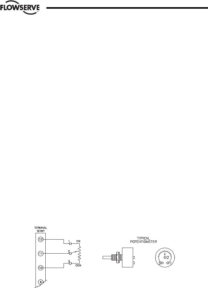
For a potentiometer input signal, the usual connections will be similar to that shown in Figure 3 with a “Close” command being generated when the potentiometer of Figure 3 is rotated to its full CCW position and an “Open” command when it is in the full CW position.
If the command signal is derived from other than a rotary pot, it is only necessary to keep in mind that a “Closed” (full CW) valve is called for when the command potentiometer presents the least resistance between terminals 10 and 11 and the most resistance between terminals 11 and 12. A full “Open” (full CCW) valve would be the reverse condition; the least resistance between terminals 11 and 12 and the most resistance between terminals 10 and 11.
If the “Command” potentiometer is reasonably linear, the actuator/valve will be approximately 50% open when the potentiometer shaft is halfway through its travel and the resistances between terminals 10 to 11 and 11 to 12 are equal.
Potentiometer input circuit boards are made in two versions, one for high resistance command circuits - 1000 ohms nominal, and one for low resistance command circuits - 135 ohms nominal.
3.2.3DC Voltage
DFP17-5V, DFP17-XV (Direct Voltage Input Signal for Digital Positioner).
For a voltage input signal, the more positive or “High” signal lead should connect to terminal 11. The less positive or “Common” lead should connect to terminal 10 [Terminal 10 is (-), Terminal 11 is (+)]
This positioner is available for use with the standard direct voltage signals: 0 to 5 VDC and 0 to 10 VDC. The positioner board is factory calibrated for one of these two signal ranges and field changes are not advised.
Section 5.4 gives the nominal resistance load which the positioner presents to the control circuit for the two signal ranges.
Figure 3
WCAIM2037 |
DataFlo Digital Electronic Positioner DFP17 Installation, Operation and Maintenance Instructions |
9 |

Flow Control
Worcester Actuation Systems
Figure 4 |
Figure 5 |
NOTE: For all input signal circuit wiring, regardless of length, shielded wiring should be used. See Section 1.2.
10 |
DataFlo Digital Electronic Positioner DFP17 Installation, Operation and Maintenance Instructions |
WCAIM2037 |
 Loading...