


Limitorque QX |
Maintenance |
|
Electronic Actuator |
and Spare Parts |
|
FCD LMENIM3314-00 - 5/11 |
||
|
||
|
|
Experience In Motion

Limitorque QX Electronic Actuator FCD LMENIM3314-00 – 5/11
Contents
1 |
Introduction |
7 |
||
|
|
1.1 |
Premise |
7 |
|
|
1.2 |
Procedure Emphasis |
7 |
|
|
1.3 |
Important Notes and Warning Statement |
8 |
|
|
1.4 |
Reference Documents |
8 |
|
|
1.5 |
This Document Applies to both QX – 90˚ Actuators and All QXM-Multi-Turn Actuators |
8 |
|
2 |
QX Actuator Subassembly |
9 |
|
|
|
2.1 QX Actuator Subassembly Components |
10 |
|
|
|
|
2.1.1 Product Description |
10 |
|
|
|
2.1.2 Storage |
10 |
|
|
|
2.1.3 Unit Weights |
11 |
|
|
2.2 |
Product Idenitification |
11 |
|
|
|
2.2.1 Initial Inspection and Recording Suggestions |
11 |
|
|
2.3 |
Maintenance |
12 |
|
|
|
2.3.1 Recommended Maintenance |
12 |
|
|
|
2.3.2 Unit Lubrication |
12 |
|
|
|
2.3.3 O-Ring Lubrication |
13 |
|
|
2.4 Subassembly Removal and Remounting Procedures |
13 |
|
|
|
2.5 |
How to Order Replacement Subassemblies |
13 |
|
|
|
2.5.1 Replacement Parts |
13 |
|
|
|
2.5.2 Returning Procedure |
14 |
|
|
2.5 |
Screw Preload (Torque) |
14 |
|
3 Remove Actuator from Mounting Adapter |
15 |
||
|
|
3.1 |
Actuator Removal with Type B4/B4E Base (Torque) |
15 |
|
|
|
3.1.1 Removal (Type B4/B4E Base) |
15 |
|
|
3.2 |
Actuator Removal with Type A1/A1E Base (Thrust)–QXM only |
17 |
|
|
|
3.2.1 Optional Thrust Base Assembly QX-1 & 2 |
17 |
|
|
|
3.2.2 Optional Thrust Base Assembly Removal |
17 |
|
|
|
3.2.3 Thrust Base Remounting |
18 |
|
|
|
3.2.4 Removal (Type A1/A1E Base) Actuator Removal Separate from Thrust Base |
19 |
|
|
|
3.2.5 Remounting(Type A1/A1E Base) Actuator Remounting Separate from Thrust Base19 |
|
|
|
|
3.2.6 Removal (Type A1/A1E Base) Actuator and Thrust Base as a Unit |
20 |
|
|
|
3.2.7 Remounting (Type A1/A1E Base) Actuator and Thrust Base as a Unit |
20 |
|
4 |
Mechanical Assemblies |
21 |
|
|
|
4.1 |
Motor Subassembly. QX-1 thru 5 |
21 |
|
|
|
4.1.1 Motor Subassembly Removal. QX-1 thru 5 |
22 |
|
|
|
4.1.2 Motor Subassembly Remounting. QX-1 thru 5 |
23 |
|
|
4.2 |
Handwheel Cover Subassembly, QX-1 thru 5 |
24 |
|
|
|
4.2.1 Handwheel Cover Subassembly Removal, QX-1 thru 5 |
24 |
|
|
|
4.2.2 Handwheel Cover Assembly Remounting |
27 |
|
|
4.3 |
Motor Cartridge Subassembly, QX-1 thru 5 |
27 |
|
|
|
4.3.1 Motor Cartridge Subassembly Removal, QX-1 thru 5 |
27 |
|
|
|
4.3.2 Motor Cartridge Assembly Remounting |
28 |
|
|
4.4 |
Gearing and Clutching |
29 |
|
|
|
4.4.1 Gearing and Clutching Removal |
31 |
|
|
|
4.4.2 Gearing and Clutching Remounting |
33 |
2 |
|
4.5 |
Pipe Plug |
35 |
|
4.6 |
Baseplate |
35 |
|
|
|
|
4.6.1 Baseplate Removal |
35 |
|
|
|
4.6.2 Baseplate Remounting |
37 |
|
|
4.7 Worm Shaft Assembly |
37 |
|

|
|
Limitorque QX Electronic Actuator |
FCD LMENIM3314-00 – 5/11 |
||
|
|
4.7.1 Worm Shaft Assembly Removal |
38 |
|
|
|
|
4.7.2 Worm Shaft Assembly Replacement |
38 |
|
|
|
4.8 |
Drive Sleeve, Stops and Encoder Shaft Assemblies |
41 |
|
|
|
|
4.8.1 Drive Sleeve, Mechanical Stops, Encoder Shaft Removal |
41 |
|
|
|
|
4.8.2 Drive Sleeve, Mechanical Stops and Encoder Shaft Assembly Remounting |
42 |
|
|
|
4.9 |
Optional Baseplate Assembly, F/FA-05 & -07 QX-1 & 2, F/FA-10 QX-3 thru 5 |
43 |
|
|
|
|
4.9.1 Optional Baseplate Removal |
43 |
|
|
|
|
4.9.2 Optional Baseplate Remounting |
43 |
|
|
|
4.10 Torque Nut |
44 |
|
|
|
|
|
4.10.1 Optional Small Baseplate Removal |
45 |
|
|
|
|
4.10.2 Optional Small Baseplate Remounting |
45 |
|
|
|
4.11 Optional Thrust Base Assembly QX-1 & 2 |
45 |
|
|
|
|
|
4.11.1 Optional Thrust Base Assembly Removal |
46 |
|
|
|
|
4.11.2 Thrust Base Remounting |
47 |
|
|
5 |
Encoder Assemblies |
48 |
|
|
|
|
5.1 |
Encoder 90 Degree Unit Removal. QX-1 thru 5 |
48 |
|
|
|
|
5.1.1 90 Degree Encoder Removal |
48 |
|
|
|
|
5.1.2 90 Degree Encoder Remounting |
49 |
|
|
|
5.2 |
Multi Turn Encoder. QXM-1 thru 5, All RPMs |
50 |
|
|
|
|
5.2.1 Multi Turn Encoder Removal |
50 |
|
|
|
|
5.2.3 Multi Turn Encoder Remounting |
52 |
|
|
6 |
Electronic Assemblies |
54 |
|
|
|
|
6.1 |
Terminal Cover |
54 |
|
|
|
|
6.1.1 Terminal Cover Removal |
54 |
|
|
|
|
6.1.2 Terminal Cover Remounting |
55 |
|
|
|
6.2 |
Controls Cover |
55 |
|
|
|
|
6.2.1 Controls Cover Removal |
56 |
|
|
|
|
6.2.2 Controls Cover Subassembly Remounting |
57 |
|
|
|
6.3 |
Control Modules |
58 |
|
|
|
|
6.3.1 Control Module Removal |
58 |
|
|
|
|
6.3.2 Control Module Subassemblies |
58 |
|
|
|
|
6.3.3 Control Module Remounting |
61 |
|
|
|
6.4 |
Terminal Block |
61 |
|
|
|
|
6.4.1 Terminal Block Shield |
62 |
|
|
|
|
6.4.2 Terminal Block Removal |
62 |
|
|
|
6.5 |
Mounting of Standard and Optional Controls |
62 |
|
|
|
|
6.5.1 Installation |
62 |
|
|
|
|
6.5.2 Removal |
67 |
|
|
|
6.6 |
Optional Transformer |
67 |
|
|
|
|
6.6.1 Optional Transformer Removal |
68 |
|
|
|
|
6.6.2 Optional Transformer Remounting |
69 |
|
|
7 |
Electronic Wiring (Cabling) |
70 |
|
|
|
|
7.1 |
AC Low Voltage Wiring (cabling) Quick Reference Guide for Control Module and |
|
|
|
|
|
Main Board. (Less than 250 VAC) |
70 |
|
|
|
|
7.1.1 AC Low Voltage Module (Version 1) |
70 |
|
|
|
|
7.1.2 AC Low Voltage Module (Version 2) |
71 |
|
|
|
|
7.1.3 DC Board Wiring (24 – 48 VDC) |
71 |
|
|
|
7.2 |
High Voltage Wiring (cabling) Quick Reference Guide. (Greater than 250 VAC) |
71 |
|
|
|
|
7.2.1 High Voltage Module |
71 |
|
|
|
7.3 |
Optional Transformer Wiring (cabling) Quick Reference Guide |
72 |
|
3 |
|
|
7.3.1 Optional Transformer Harness Wiring Used With Low Voltage Control Module |
73 |
|
|
|
|
7.3.2 Optional Transformer Harness Wiring Used With High Voltage Control Module |
73 |
|
|
|
|
7.3.3 Optional Transformer Harness Routing Used With High Voltage Control Module |
73 |
|
|
|
7.4 |
Terminal Block Wiring Harness Numbers |
74 |
|
|
flowserve.com

Limitorque QX Electronic Actuator FCD LMENIM3314-00 – 5/11
8 Spares and Replacement Parts |
75 |
|
8.1 |
Guidelines for Recommended Spare Parts |
75 |
|
8.1.1 Wear Components |
75 |
|
8.1.2 Bearings, O-rings, and Seals |
75 |
|
8.1.3 Critical Components |
75 |
8.2 |
Recommended Spare Parts for QX Actuators |
76 |
|
8.2.1 Commissioning and Startup |
76 |
|
8.2.2 Short-Term Duty |
76 |
|
8.2.3 Long-Term Duty |
76 |
|
8.2.4 Severe Duty |
76 |
8.3 |
Other Concerns |
77 |
9 Regulatory Information |
78 |
|
9.1 |
Declaration of Conformity |
78 |
9.2 |
Specific Conditions for Use — Atex/Cenelec/IECEx Applications |
80 |
9.3 |
Statement of Compliance with Applicable European Directives |
80 |
Figures
|
Figure 2.1 Typical QX Actuator |
7 |
|
Figure 2.2 QX Nameplate |
11 |
|
Figure 2.3 QX Nameplate |
11 |
|
Figure 2.4 QX Oil fill /Plug Locations (QX-1 thru 5) |
13 |
|
Figure 3.1 Torque Nut, F/FA-10, QX-1 & 2 and F/FA-12 and -14, QX-1 thru 5 |
15 |
|
Figure 3.2 Torque Nut, F/FA-05 and -07, QX-1& 2 and F/FA-10, QX-1 thru 5 |
16 |
|
Figure 3.3 Optional Thrust Base Assembly |
17 |
|
Figure 3.4 Optional Thrust Base Subassembly |
18 |
|
Figure 4.1 Motor Cover and Motor Subassembly Removal |
21 |
|
Figure 4.2 Motor Subassembly, Item11 |
22 |
|
Figure 4.3 Motor Bracket Orientation View |
23 |
|
Figure 4.4 Handwheel Cover Assembly |
24 |
|
Figure 4.5 Handwheel Cover Subassembly, Item 10. QX-1 & 2 |
25 |
|
Figure 4.6 Handwheel Cover Subassembly, Item 10. QX-3 thru 5 |
26 |
|
Figure 4.7 Handwheel Subassembly, Item 10-4. QX-1 & 2 shown |
26 |
|
Figure 4.8 Motor Cartridge Assembly Removal |
27 |
|
Figure 4.9 Motor Cartridge Subassembly, Item 5 |
28 |
|
Figure 4.10 Gearing and clutching, QX-1 & 2 |
29 |
|
Figure 4.11 Gearing and clutching, QX-3 thru 5 |
30 |
|
Figure 4.12 Clutch Shaft Subassembly, Item 6. QX-1 & 2 |
32 |
|
Figure 4.13 Clutch Shaft Subassembly, Item 6. QX-3 thru 5 |
32 |
|
Figure 4.14 Clutch Shaft Subassembly, Item 7 |
33 |
|
Figure 4.15 Clutch Fork Shaft Remounting |
34 |
|
Figure 4.16 Declutch Spring Assembly View. QX-1 & 2 shown |
34 |
|
Figure 4.17 Pipe Plug |
35 |
|
Figure 4.18 Baseplate, F/FA-10 QX-1 & 2, F/FA-12 & 14, QX-3 thru 5 |
36 |
|
Figure 4.19 F/FA-10 QX-1 & 2, F/FA-12 & 14, QX-3 thru 5 Baseplate Subassembly, Item 3 |
36 |
|
Figure 4.20 Worm Shaft |
38 |
|
Figure 4.21 Drive Sleeve, Stops, and Encoder Shaft Assembly |
40 |
|
Figure 4.22 Multi-turn Encoder Shaft Subassembly (Item 1-6) |
41 |
4 |
Figure 4.23 Stop Groove View |
42 |
|
Figure 4.24 F/FA-05 / 07, QX-1 & 2 or F/FA-10, QX-3 thru 5 Optional Baseplate |
43 |
|
Figure 4.25 Torque nut, F/FA-10, QX-1 & 2 and F/FA-12 and -14, QX-1 thru 5 |
44 |
|
Figure 4.26 Torque nut, F/FA-05 and -07, QX-1 & 2 and F/FA-10, QX-1 thru 5 |
44 |
|
Figure 4.27 Optional Thrust Base Assembly QXM Only |
45 |

Limitorque QX Electronic Actuator FCD LMENIM3314-00 – 5/11 |
|
||
Figure 4.28 Optional Thrust Base Subassembly |
46 |
|
|
Figure 5.1 90º Encoder Assembly |
48 |
|
|
Figure 5.2 Encoder To Subassembly, Item 14-1 |
49 |
|
|
Figure 5.3 Encoder To Unit Assembly View |
49 |
|
|
Figure 5.4 Multi-turn Encoder Assembly |
50 |
|
|
Figure 5.5 6.5-Turn Spur Gear Subassembly (Item 17-2) |
51 |
|
|
Figure 5.6 20-Turn Spur Gear Subassembly (Item 17-2) |
52 |
|
|
Figure 5.7 20-Turn Gear Slot Orientation View |
52 |
|
|
Figure 6.1 Terminal Cover Assembly |
54 |
|
|
Figure 6.2 Terminal Cover Subassembly |
55 |
|
|
Figure 6.3 Controls Cover Assembly |
56 |
|
|
Figure 6.4 Controls Cover Subassembly |
57 |
|
|
Figure 6.5 Control Module Assembly |
58 |
|
|
Figure 6.6 Low Voltage (Less than 250 VAC) Control Module Subassembly |
59 |
|
|
Figure 6.7 High Voltage (Greater than 250 VAC) Control Module Subassembly |
59 |
|
|
Figure 6.8 DCV Control Module Subassembly |
60 |
|
|
Figure 6.9 Bracket Connector Retainer Assembly |
61 |
|
|
Figure 6.10 Terminal Block Assembly |
62 |
|
|
Figure 6.11 Terminal Block Shield |
62 |
|
|
Figure 6.12 Quik Power Without Option Boards |
64 |
|
|
Figure 6.13 Quik Power With Option Boards |
65 |
|
|
Figure 6.14 Option Board Assembly |
66 |
|
|
Figure 6.15 Optional Transformer Assembly |
67 |
|
|
Figure 6.16 Optional Transformer Subassembly |
68 |
|
|
Figure 7.1 Low Voltage QX Unit Wiring Connections |
70 |
|
|
Figure 7.2 Low Voltage QX Unit Wiring Connections (Version 2) |
71 |
|
|
Figure 7.3 DC QX Unit Wiring Connections |
71 |
|
|
Figure 7.4 High Voltage QX Unit Wiring |
72 |
|
|
Figure 7.5 Typical Toroid Transformer Label |
72 |
|
|
Figure 7.6 Optional Low Voltage Transformer Harness Wiring |
73 |
|
|
Figure 7.7 Optional High Voltage Transformer Harness Wiring |
73 |
|
|
Figure 7.8 High Voltage Optional Transformer Harness Assembly Routing |
73 |
|
|
Figure 7.9 Optional Transformer Harness Connector to Wire Position per Supply Voltage |
74 |
|
|
Figure 7.10 Terminal Block Wiring Harness And Connector Numbers |
74 |
|
|
Tables |
|
|
|
Table 2.1 Typical QX Actuator Subassembly |
10 |
|
|
Table 2.2 QX Unit Weights |
11 |
|
|
Table 2.3 QX-1 thru 5 Oil Capacities |
12 |
|
|
Table 2.4 Screw Preload Torque |
14 |
|
|
Table 3.1 Torque Nut, F/FA-05 and -07, QX-1 & 2 and F/FA-10, QX-1 thru 5 |
16 |
|
|
Table 3.2 Optional Thrust Base Assembly |
17 |
|
|
Table 3.3 Optional Thrust Base Subassembly |
18 |
|
|
Table 4.1 Motor Parts List |
21 |
|
|
Table 4.2 Motor Subassembly, Item 11 |
22 |
|
|
Table 4.3 Handwheel Cover Assembly |
24 |
|
|
Table 4.4 Handwheel Cover Subassembly Item 10. QX -1 & 2 |
25 |
|
|
Table 4.5 Handwheel Cover Subassembly, Item 10. QX-3 thru 5 |
25 |
|
5 |
Table 4.6 Handwheel Subassembly, Item 10-4 |
26 |
|
|
|
|
||
Table 4.7 Motor Cartridge Assembly Removal |
27l |
|
|
Table 4.8 Motor Cartridge Subassembly, Item 5 |
28 |
|
|
Table 4.9 Gearing and Clutching, QX-1 & 2 |
29 |
|
|
flowserve.com

Limitorque QX Electronic Actuator |
FCD LMENIM3314-00 – 5/11 |
Table 4.10 Gearing and Clutching, QX-3 thru 5 |
30 |
Table 4.11 Clutch Shaft Subassembly, Item 6. QX-1 & 2 |
31 |
Table 4.12 Clutch Shaft Subassembly Item 6. QX-3 Thru 5 |
32 |
Table 4.13 Clutch Shaft Subassembly Item 7 |
33 |
Table 4.14 Pipe Plug |
35 |
Table 4.15 Baseplate F/FA-10 QX-1 & 2, F/FA-12 & 14 QX-3 thru 5 |
36 |
Table 4.16 Baseplate Subassembly Item 3 |
36 |
Table 4.17 Worm Shaft Parts List |
37 |
Table 4.18 Drive Sleeve, Stops, and Encoder Shaft Assembly |
40 |
Table 4.19 Multi-turn Encoder Shaft Subassembly (Item 1-6) |
41 |
Table 4.20 Optional Baseplate Removal |
43 |
Table 4.21 Torque nut, F/FA-10, QX-1 & 2 and F/FA-12 and -14, QX-1 thru 5 |
44 |
Table 4.22 Torque nut F/FA-05 and -07 QX-1 & 2 and F/FA-10, QX-1 thru 5 |
44 |
Table 4.23 Optional Thrust Base Assembly |
45 |
Table 4.24 Optional Thrust Base Subassembly |
46 |
Table 5.1 90º Encoder Assembly |
48 |
Table 5.2 Encoder Subassembly, Item 14-1 |
49 |
Table 5.3 Multi-Turn Encoder Assembly |
50 |
Table 5.4 6.5-Turn Spur Gear Subassembly (Item 17-2) |
51 |
Table 5.5 20-Turn Spur Gear Subassembly (Item 17-2) |
51 |
Table 6.1 Terminal Cover Assembly |
54 |
Table 6.2 Terminal Cover Subassembly |
55 |
Table 6.3 Controls Cover Assembly |
55 |
Table 6.4 Controls Cover Subassembly |
56 |
Table 6.5 Control Module Assembly |
57 |
Table 6.6 Low Voltage (Less than 250 VAC) Control Module Subassembly |
58 |
Table 6.7 High Voltage (Greater than 250 VAC) Control Module Subassembly |
59 |
Table 6.8 DCV Control Module Subassembly |
60 |
Table 6.9 Terminal Block Assembly |
61 |
Table 6.10 Control Board Connectors |
66 |
Table 6.11 Screw Part Numbers |
67 |
Table 6.12 Optional Transformer Assembly |
67 |
Table 6.13 Optional Transformer Subassembly |
68 |
Table 7.1 Connector to Wire Position per Supply Voltage |
74 |
6

Limitorque QX Electronic Actuator FCD LMENIM3314-00 – 5/11
1 Introduction
1.1 Premise
The Flowserve Limitorque QX actuator components are separated into subassembly groupings. This manual covers the removal and remounting procedures for each subassembly group. Use these instructions when disassembly is required for service, maintenance or parts replacement.
1.2 Procedure Emphasis
Please refer to the following methods used to emphasize text throughout this manual. Safety Warnings, Cautions and |
|
Notes present material that is important to user safety. Be sure to read any safety notices you see as they could prevent |
|
equipment damage, personal injury or even death to you or a co-worker. |
7 |
Safety notices are presented in this manual in three forms:
flowserve.com

Limitorque QX Electronic Actuator FCD LMENIM3314-00 – 5/11
cWARNING: Refers to personal safety. Alerts the user to potential danger. Failure to follow warning notices could result in personal injury or death.
aCAUTION: Directs the user’s attention to general precautions that, if not followed, could result in personal injury and/or equipment damage.
NOTE: Highlights information critical to the user’s understanding of the procedure.
Bold text stresses attention to the details of the procedure.
1.3 Important Notes and Warning Statements
Please read this Maintenance and Spare Parts Manual carefully and completely before attempting to store or perform maintenance on your QX valve actuator. Further installation, setup and operation instructions are available in the Installation and Operation manual (LMENIM3306) attached to the actuator declutch lever bracket at shipment.
cWARNING: Be aware of electrical hazards within the actuator and high-pressure hazards of the attached valve or other actuated device when installing or performing maintenance on your QX actuator. Failure to observe these precautions could result in serious bodily injury, damage to the equipment or operational difficulty.
cWARNING: Do not manually operate actuator with devices other than installed handwheel and declutch lever. Using additive force devices (cheater bars, wheel wrenches, pipe wrenches or other devices of this nature) on the actuator handwheel or declutch lever may cause serious personal injury and/or damage to the actuator or valve.
1.4Reference Documents
•Protection, Control and Monitoring features of MX/QX Electric Actuators (Bulletin LMENTB2300)
•QX Control, Performance and Value in Quarter-turn Electric Valve Actuators (Bulletin LMENBR3302)
•QX Installation Manual (Bulletin LMENIM3306)
•QX Quick Mount and Start (Bulletin LMENIM3313)
1.5This document applies to both QX – 90 degree actuators and all QXM-multi-turn actuators.
The latest revisions to these documents are available on-line from Flowserve Limitorque’s website, www.flowserve. com or at www.limitorque.com
8

|
Limitorque QX Electronic Actuator FCD LMENIM3314-00 – 5/11 |
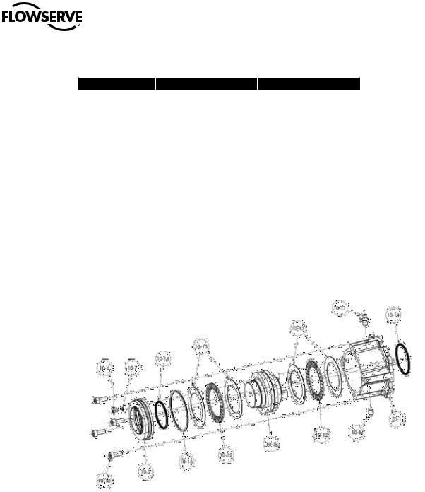
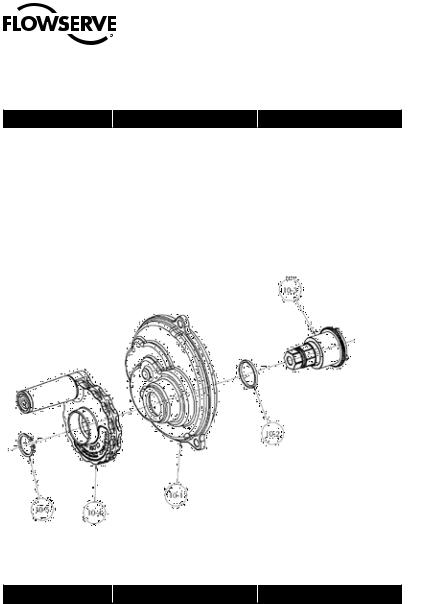
2Figure 2.1 - Typical QX Actuator |
QX Actuator Subassembly |
NOTE: QX-1 and 2 90° unit shown. |
9 |
|
flowserve.com

Limitorque QX Electronic Actuator FCD LMENIM3314-00 – 5/11
2.1 QX Actuator Subassembly Components
Table 2.1 - Typical QX Actuator Subassembly
Item Number |
Description |
|
|
3 |
Baseplate |
|
|
5 |
Motor cartridge |
|
|
6 |
Clutch shaft |
|
|
7 |
Clutch fork |
|
|
10 |
Handwheel cover |
|
|
10-4 |
Handwheel |
|
|
11 |
Motor |
|
|
14-1 |
Encoder |
|
|
14-4 |
Terminal block |
|
|
14-8 |
Power controls |
|
|
15-3 |
Controls cover |
|
|
2.1.1 Product Description
Your QX actuator controls the opening and closing travel of valves and other actuated devices. OPEN and CLOSED limits are protected by an absolute encoder that provides optical sensing of valve position and measures valve position in both motor and handwheel operation. No battery or backup power supply is required. Output torque is derived from current, voltage and temperature. If the preset torque is exceeded, the motor shuts off. As a result of this reliable and advanced protection technology, all valve and other actuated devices are protected from potential damage from overload, improper seating and foreign obstructions.
A range of control and network options is available which can be easily added to the control capabilities already available on a standard actuator. Contact your local Limitorque distributor or Limitorque sales office for further information.
2.1.2 Storage
Storage Recommendations
Your QX actuator is double-sealed and weather-proof as shipped, even for explosion-proof applications, providing all compartment covers and cable entry plugs are left intact. Actuators should be stored in a clean, dry, protected warehouse until ready for installation. If actuators must be stored outdoors, they should be stored off the ground and high enough to prevent being immersed in water or buried in snow.
Preferred Storage Orientation
Your QX actuator should be stored with terminal compartment in the vertical position and the drive base down to obtain optimum service life.
10
Limitorque QX Electronic Actuator FCD LMENIM3314-00 – 5/11
2.1.3Unit Weights
Table 2.2 - QX Unit Weights
Unit |
lb. |
kg |
|
|
|
QX-1 |
40 |
18 |
|
|
|
QX-2 |
42 |
19 |
|
|
|
QX-3 |
80 |
36 |
|
|
|
QX-4 |
80 |
36 |
|
|
|
QX-5 |
80 |
36 |
|
|
|
NOTE: Weights include B4 stem nut and lubricant.
2.2 Product Identification
2.2.1 Initial Inspection and Recording Suggestions
Upon receipt of the actuator, several steps should be initially followed to ensure condition of equipment and to establish proper record keeping.
1.After removing the actuator from the shipping carton or skid, thoroughly examine it for any physical damage which may have occurred during shipment. If you note any damage, immediately report the damage to the transport company and call Limitorque for further assistance.
2.A nameplate with important information is attached to each actuator. Record the following information for use when you need to contact Limitorque with any questions about your actuator:
•Unit type/size
•Flowserve Limitorque order number
•Serial number
Figure 2.2 - QX Nameplate |
Figure 2.3 - QX Nameplate |
11
flowserve.com

Limitorque QX Electronic Actuator FCD LMENIM3314-00 – 5/11
2.3 Maintenance
2.3.1 Recommended Maintenance
Under normal operating conditions, the QX is a maintenance-free actuator. Therefore, for normal applications, the actuator will require no formal maintenance program. However, if the actuator is used under severe service conditions or operated in a Hazardous Location, the following maintenance procedures are required:
1.Check the oil level every 50 hours of operation at a minimum. Where conditions are severe due to frequent operation or high ambient temperatures, a more regular inspection interval should be maintained.
2.Change the gear oil every 100 hours of operation. See section 2.3.2 Unit Lubrication.
3.All ball bearings, oil seals, O-rings and quad-rings are to be replaced after 450 hours of operation. See sections 2-3-2 thru 2-3-3.
Clean and lubricate the valve stem regularly to avoid torque build-up and wear due to silting and corrosion. Infrequent operation can lead to corrosion and contamination of the valve stem thread lubricant. Check any thrust bearings that are fitted to the actuator for proper lubrication at regular intervals.
2.3.2 Unit Lubrication
Change oil every 100 hours of operation or if water or other foreign material is found during oil inspection.
Oil Level Inspection and Fill Criteria
To avoid pressurization of the gearcase, the following recommended oil capacities should not be exceeded: (Reference Table 2.3 for oil capacities when mounted in varying positions)
•Actuator viewed in upright position (terminal compartment up / base down) Oil level should be approximately 1 inch (25.4 mm) below the outer surface of the housing at the oil fill port.
•Actuators mounted in other orientations than the upright position should have their oil capacities maintained.
Fill through the highest oil fill port until the oil is at a level that will contact the bottom of the plug when installed in the oil fill port.
NOTE: Do not overfill! Oil will expand during actuator operation. Actuators are shipped with an oil volume suitable for any mounting position. When checking the factory-supplied oil level, excess oil may drain from the highest oil fill port due to the various mounting orientations of each application.
Table 2.3 QX-1 thru 5 Oil Capacities
Unit Description |
Fluid Ounces |
Litres |
|
|
|
QX 1/2 |
26 |
0.77 |
|
|
|
QX-3/4/5 |
80 |
2.36 |
|
|
|
Lubrication Data
Oil Specification – all models
-30°C to +70°C (-22o to + 158o F) units require oil per Petro-Canada SHB-68 or Mobil SHC626
-60°C to +40°C (-76o to + 104o F) units require oil that is 50% Petro Canada SHB-68 with 50% Soltex PAO4
12
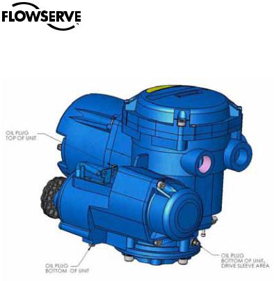
Limitorque QX Electronic Actuator FCD LMENIM3314-00 – 5/11
Figure 2.4 - QX Oil fill /Plug Locations (QX-1 thru 5)
2.3.3 O-Ring and Lubrication
O-rings and seals should be replaced any time an actuator is disassembled. Lubricate with a substance that is compatible with Buna N seals.
2.4 Subassembly Removal and Remounting Procedures
This manual divides each QX actuator subassembly into a Removal and Remounting procedure. Use the following procedures to remove subassemblies for inspection, repair or replacement. Some subassemblies require prior subassembly removal before allowing the desired subassembly removal. Note the First Remove instructions at the beginning of each subassembly removal procedure. Remove these subassemblies first, and then remove the
desired subassembly according to the instructions. Once removed, evaluate subassembly components to determine requirement for a new subassembly. If a new subassembly is required, see Section 2.5. Once components have been identified and replaced, remount following the appropriate Remounting procedures.
2.5 How to Order Replacement Subassemblies
2.5.1 Replacement Parts
Replacement parts are sold in modular subassemblies; therefore, when part replacement is required, order parts at the subassembly levels as shown in this manual. Parts may be ordered from your local Limitorque representative (www. flowserve.com) or direct from the factory:
Telephone: 1-434-528-4400
Fax: 1-434-845-9736
Please have the following information, found on the actuator nameplate, available to help us facilitate your order:
•Unit type/size
•Limitorque order number
•Serial number
13
flowserve.com

Limitorque QX Electronic Actuator FCD LMENIM3314-00 – 5/11
2.5.2 Return Procedure
When parts are identified for warranty or other component replacement, a Return Material Authorization (RMA) must be obtained from Flowserve. Contact factory for a RMA number (see contact information in section 2.5.1). All returned parts must be accompanied by documentation with the following information to obtain credit for returned goods:
•Return Material Authorization (RMA)
•Unit type/size
•Flowserve Limitorque order number
•Serial number
Return parts to the address listed below:
Limitorque Actuation Systems
5114 Woodall Road
Lynchburg, VA 24502
2.5 Screw Preload (Torque)
Torque applied to each size screw used in the QX:
Table 2.4 - Screw Preload Torque
Screw |
Screw Preload |
|
|
|
|
M10 |
10-12 ft-lbs |
|
|
|
|
M10 used on Base Plate |
17-20 ft-lbs |
|
QX-3 / 4 / 5 |
||
|
||
|
|
|
M8 |
6-8 ft-lbs |
|
|
|
|
M6 |
24-36 inch lbs |
|
|
|
|
M5 |
15-20 inch lbs |
|
|
|
|
M4 |
8-12 inch lbs |
|
|
|
|
M3 |
60-70 inch ounces |
|
|
|
|
M2 |
18-22 inch ounces |
|
|
|
14
Limitorque QX Electronic Actuator FCD LMENIM3314-00 – 5/11
3 Remove Actuator from Mounting Adapter
3.1 Actuator Removal with Type B4/B4E Base (Torque)
3.1.1 Removal (Type B4/B4E Base)
Step 1
cWARNING: Hazardous Voltage! Turn off all power sources to actuator before removing actuator from mounting plate. Power sources may include main power or control power. If necessary, disconnect incoming power leads L1, L2, L3, and control wiring from the terminal block.
Figure 3.1 - Torque Nut, F/FA-10, QX-1 & 2 and F/FA-12 and -14, QX-1 thru 5
15
flowserve.com
Limitorque QX Electronic Actuator FCD LMENIM3314-00 – 5/11
Table 3.1 Torque Nut, F/FA-05 and -07, QX-1 & 2 and F/FA-10, QX-1 thru 5
ITEM NUMBER |
DESCRIPTION |
QTY. |
|
|
|
13-7 |
SCOKET HEAD CAP SCREW |
1 |
|
|
|
16-7 |
TORQUE NUT |
1 |
|
|
|
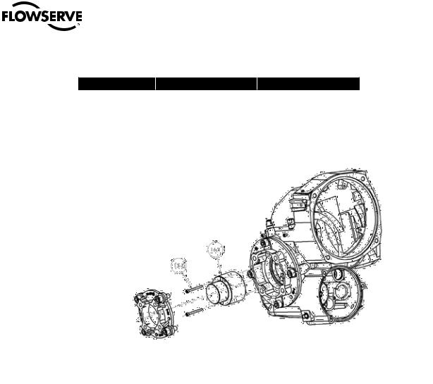
Figure 3.2 - Torque Nut, F/FA-05 and -07, QX-1& 2 and F/FA-10, QX-1 thru 5
Remove the bolts that secure the actuator to the mounting adapter. If type B4 or B4E base is used in addition to the standard type B4 or B4E baseplate, you may leave the B4 base attached to the mounting adapter and remove the actuator only. Or if required, you may remove the bolts that mount type B4 base to mounting adapter. This will allow actuator removal along with optional B4 base.
Step 2
cWARNING: Potential high-pressure vessel! Before disassembling your actuator, ensure that the valve or other actuated device is isolated and is not under pressure.
Lift the actuator from mounting adapter.
3.1.2 Remounting (Type B4/B4E Base)
Step 3
Ensure stem nut (#1-22) is secured inside actuator drive sleeve with retaining ring (#1-23). Lower the actuator onto the mating component, making sure to align stem nut key and keyway with mating component.
Step 4
Ensure that the actuator and mounting adapter flange mating holes are aligned correctly.
Sept 5
16
cWARNING: Hazardous Voltage! Turn off all power sources before rewiring incoming power leads L1, L2, L3, and control wiring in the terminal block.
Secure the actuator to the mounting adapter with mounting bolts.
Limitorque QX Electronic Actuator FCD LMENIM3314-00 – 5/11
Step 6
Reconnect incoming power leads L1, L2, L3, and control wiring to the terminal block. Restore power source when ready for operation.
3.2 Actuator Removal with Type A1/A1E Base (Thrust) – QXM only
3.2.1 Optional Thrust Base Assembly QX-1 & 2
Table 3.2 - Optional Thrust Base Assembly
ITEM NUMBER |
DESCRIPTION |
QTY. |
|
|
|
16-10 |
TORQUE NUT |
1 |
|
|
|
16-11 |
BUSHING |
1 |
|
|
|
16-12 |
O'-RING |
1 |
|
|
|
16-13 |
O'-RING |
1 |
|
|
|
16-14 |
ADAPTER PLATE |
1 |
|
|
|
16-15 |
SOCKET HEAD CAP SCREWS |
4 |
|
|
|
16-16 |
SPACER, PILOT, ISO ONLY |
1 |
|
|
|
16-17 |
THRUST BASE ASSEMBLY |
1 |
|
|
|
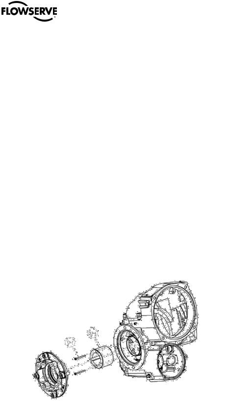
Figure 3.3 - Optional Thrust Base Assembly
3.2.2 Optional thrust base assembly removal.
Step 1
Remove the four (4) screws (# ) and remove the thrust base subassembly (#16-17) by sliding the base down. If base is ISO remove the spacer (pilot) (#16-16).
Step 2
Remove the four (4) screws (# 16-15) and remove the adapter plate (#16-14) and torque nut (#16-10). Item (#16-11) bushing is pressed into adapter plate and cannot be removed. The torque nut is held in place by the unit drive sleeve
and the bushing (#16-11).
17
flowserve.com
Limitorque QX Electronic Actuator FCD LMENIM3314-00 – 5/11
Table 3.3 - Optional Thrust Base Subassembly
ITEM NUMBER |
DESCRIPTION |
QTY. |
|
|
|
10-1 |
HOUSING, THRUST BASE |
1 |
|
|
|
10-2 |
PILOT, THRUST BASE |
1 |
|
|
|
10-3 |
THRUST NUT |
1 |
|
|
|
10-6 |
SOCKET HEAD CAP SCREWS |
1 |
|
|
|
10-7 |
FLAT WASHER |
1 |
|
|
|
10-8 |
RELIEF FITTING |
1 |
|
|
|
10-10 |
SOCKET HEAD CAP SCREWS |
4 |
|
|
|
10-11 |
GREASE FITTING |
1 |
|
|
|
10-12 |
NEEDLE BEARING |
2 |
|
|
|
10-13 |
THRUST RACE |
2 |
|
|
|
10-14 |
QUAD RING |
1 |
|
|
|
10-15 |
O'-RING |
1 |
|
|
|
10-16 |
QUAD RING |
1 |
|
|
|
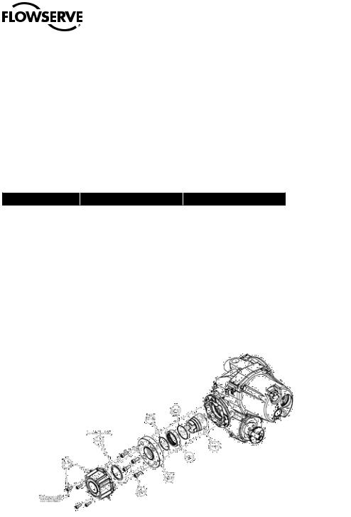
Figure 3.4 - Optional Thrust Base Subassembly
|
3.2.3 Thrust base remounting |
|
Step 1 |
|
Place QX torque nut (#16-10) into unit drive sleeve (#1-11) aligning nut lugs to drive sleeve slots. |
|
Step 2 |
|
Lightly lubricate ‘O’-rings (#16-12) and (#16-13) and insert into bushing (#16-11) that is pressed into adapter plate |
|
(#16-14). Slide adapter plate and bushing over end of torque nut and aligning to unit baseplate. Insert screws (#16-15) |
|
into adapter plate holes and tighten. |
18 |
Step 3 |
|
|
|
Align thrust base subassembly nut lugs (#10-3) with QX torque nut (#16-10) slots and slide thrust base on to QX |
|
unit baseplate aligning pilots. Note; For ISO thrust base pilot spacer (#16-16) must be used to align thrust base to QX |
|
baseplate. Insert screws (#10-10) into thrust base holes and tighten |

Limitorque QX Electronic Actuator FCD LMENIM3314-00 – 5/11
NOTE: Two procedure options are available for removing the actuator and the thrust base:
1.Remove actuator from the thrust base, leaving the base mounted to the mounting flange or removing the thrust base separately
2.Remove actuator and thrust base as a unit from the mounting flange.
3.2.4 Removal (Type A1/A1E Base) Actuator Removal Separate from Thrust Base
STEP 1
cWARNING: Hazardous Voltage! Turn off all power sources to actuator before removing actuator from mounting plate. Power sources may include main power or control power. If necessary, disconnect incoming power leads L1, L2, L3, and control wiring from the terminal block.
Remove the bolts (#10-10) that secure the actuator to the thrust base assembly (#10).
STEP 2
cWARNING: Potential high-pressure vessel! Before disassembling your actuator, ensure that the valve or other actuated device is isolated and is not under pressure.
Lift actuator from thrust base assembly (#10).
STEP 3
cWARNING: Potential for actuated device to change position! The thrust base will maintain position only if nonbackdriving thread lead is used. Ensure proper thread lead is used in your application before allowing thrust base to be used for maintaining position when actuator is removed.
Thrust base removal (if required)
The valve position will be maintained if a locking thread lead is used on the valve stem. If thrust base removal is required, use the following removal procedure.
Remove the bolts that secure the thrust base to the mounting adapter.
STEP 4
Rotate the thrust base (#10) until it feeds off the threaded stem.
3.2.5 Remounting (Type A1/A1E Base) Actuator Remounting Separate from Thrust Base
STEP 5
Thrust base remounting (if required)
Ensure the thrust base stem nut has the two lugs positioned upward to engage with the drive sleeve slots when actuator is reinstalled onto thrust base. Thread thrust base back onto mounting adapter.
STEP 6
Secure thrust base to mounting adapter with mounting bolts.
STEP 7
Actuator remounting
Lower the actuator onto the thrust base, making sure thrust nut lugs align and properly engage with drive sleeve slots.
STEP 8 |
19 |
Install bolts (#10-10) to secure the actuator to the thrust base assembly (#10).
flowserve.com

Limitorque QX Electronic Actuator FCD LMENIM3314-00 – 5/11
STEP 9
cWARNING: Hazardous Voltage! Turn off all power sources before rewiring incoming power leads L1, L2, L3, and control wiring in the terminal block.
Reconnect incoming power leads L1, L2, L3, and control wiring to the terminal block. Restore power source when ready for operation.
3.2.6 Removal (Type A1/A1E Base) Actuator and Thrust Base as a Unit
STEP 1
cWARNING: Hazardous Voltage! Turn off all power sources to actuator before removing actuator from mounting plate. Power sources may include main power or control power. If necessary, disconnect incoming power leads L1, L2, L3, and control wiring from the terminal block.
Actuator and thrust base removal
Remove the bolts that secure the actuator and thrust base (#10) to the mounting adapter.
STEP 2
cWARNING: Potential high-pressure vessel! Before disassembling your actuator, ensure that the valve or other actuated device is isolated and is not under pressure.
Declutch the actuator to manual mode.
STEP 3
Rotate the handwheel until the actuator lifts off the threaded stem.
3.2.7 Remounting (Type A1/A1E Base) Actuator and Thrust Base as a Unit
STEP 4
Actuator and thrust base remounting
Declutch the actuator to manual mode. Lift actuator up to the threaded stem and carefully align threads with thrust base threaded stem nut.
STEP 5
Rotate the handwheel to lower the actuator along the threaded stem and onto the mounting adapter plate.
STEP 6
Install the mounting bolts to secure the actuator and thrust base (#10) to the mounting adapter.
STEP 7
cWARNING: Hazardous Voltage! Turn off all power sources before rewiring incoming power leads L1, L2, L3, and control wiring in the terminal block.
Reconnect incoming power leads L1, L2, L3, and control wiring to the terminal block. Restore power source when ready for operation.
20
Limitorque QX Electronic Actuator FCD LMENIM3314-00 – 5/11
4 Mechanical Assemblies
4.1 Motor subassembly. QX-1 thru 5.
NOTE: Proper motor testing is required when replacing motor. Consult your Limitorque representative or the
Limitorque factory to replace with correct motor.
Table 4.1 - Motor Parts List
ITEM NUMBER |
DESCRIPTION |
QTY. |
11 |
MOTOR |
1 |
|
|
|
13-4 |
SOCKET HEAD CAP SCREWS |
5 |
|
|
|
15-1 |
'O'-RING |
1 |
|
|
|
15-2 |
COVER, MOTOR |
1 |
|
|
|
15-6 |
SOCKET HEAD CAP SCREWS |
3 |
|
|
|
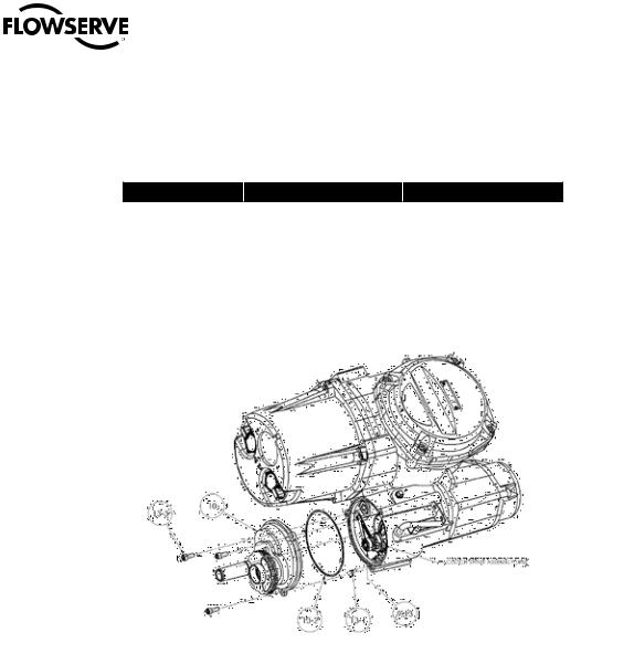
Figure 4.1 - Motor Cover and Motor Subassembly Removal
21
flowserve.com
Limitorque QX Electronic Actuator FCD LMENIM3314-00 – 5/11
4.1.1 Motor subassembly Removal. QX-1 thru 5.
Step 1
cWARNING: Hazardous Voltage! Turn off all power sources to actuator before removing motor assembly. Power sources may include main power or control power.
Using a M6 hex key, remove the three M8 screws (#15-6) that mount the motor cover and remove cover (#15-2) and ‘O’-ring (#15-1) from unit assembly.
NOTE: The controls cover must also be removed to disconnect the motor cable from the motor controller if the motor is to be completely removed. See Section 6.2 for controls cover removal, Section 7.1 for motor connector placement.
Step 2
aCAUTION: The rotor is not connected to the motor housing; when removing the motor, ensure the rotor is carefully removed and not dropped from the motor housing.
Using a M3 hex key, remove the five M4 screws (#13-4) that mount the motor assembly. Remove the motor assembly (#11) from unit by sliding motor out of the unit and if needed disconnect motor connector from motor control board and slide wiring out of unit.
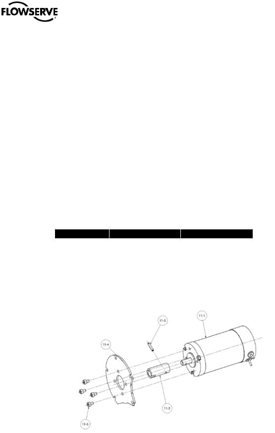
Table 4.2 Motor Subassembly, Item 11
ITEM NUMBER |
DESCRIPTION |
QTY. |
|
|
|
11-1 |
MOTOR |
1 |
|
|
|
11-2 |
COUPLING |
1 |
|
|
|
11-3 |
SPIRAL PIN |
1 |
|
|
|
11-4 |
PLATE, MOTOR MOUNTING |
1 |
|
|
|
11-5 |
SOCKET HEAD CAP SCREWS |
1 |
|
|
|
Figure 4.2 - Motor Subassembly, Item11
22
Limitorque QX Electronic Actuator FCD LMENIM3314-00 – 5/11
4.1.2 Motor subassembly Remounting. QX-1 thru 5.
Step 1
cWARNING: Hazardous Voltage! Turn off all power sources to actuator before removing motor assembly. Power sources may include main power or control power.
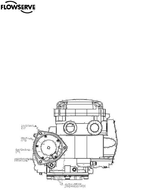
If motor wiring was removed reroute wiring thru housing over to the motor control board. Do not connect motor wiring connector until motor is mounted in unit. Rotate motor coupling slot to correct position on motor to match motor cartridge pin orientation noting motor bracket position to unit housing per Figure 4.3 and slide motor assembly into housing aligning the motor coupling bore and slot to the motor cartridge shaft and pin and the motor bracket to the unit housing.
(See Figure 4.3 listed for motor bracket orientation to unit housing).
Figure 4.3 - Motor Bracket Orientation View
Step 2
Reconnect motor wiring connector to motor control board. Install the five M4 screws (#13-4) and tighten.
(See section 7 for motor wiring connection).
Step 3
Lightly lubricate ‘O’-ring (#15-1) and install around motor cover spigot/pilot (#15-2). Slide motor cover spigot/pilot into the unit housing.
Step 4
Fit the 3 screws (#15-6) into motor cover mounting holes and tighten to torque in section 2.
23
flowserve.com
Limitorque QX Electronic Actuator FCD LMENIM3314-00 – 5/11
4.2 Handwheel cover subassembly, QX-1 thru 5.
NOTE: Sections 4.2 – 4.8 require the actuator to be removed from the mounting plate and the oil drained.
Table 4.3 - Handwheel Cover Assembly
ITEM NUMBER |
DESCRIPTION |
QTY. |
|
|
|
10 |
HANDWHEEL COVER ASSY |
1 |
|
|
|
13-1 |
DOWEL PIN |
1 |
|
|
|
13-2 |
'O'-RING |
1 |
|
|
|
13-3 |
SOCKET HEAD CAP SCREW |
3 |
|
|
|
Figure 4.4 - Handwheel Cover Assembly
c WARNING: Do not manually operate the actuator with devices other than the installed handwheel and declutch lever. Using force beyond the ratings of the actuator and/or additive forces such as cheater bars, wheel wrenches, pipe wrenches, or other devices on the actuator handwheel or declutch lever may cause serious personal injury and/or damage to the actuator and valve.
4.2.1 – Handwheel cover subassembly Removal, QX-1 thru 5
Step 1
c WARNING: Potential to operate while dangerous mechanical parts are exposed during subassembly removal. To prevent injury, turn off all power sources to actuator before removing top-mounted handwheel assembly. Power sources may include main power or control power.
Using a M5 hex key, remove the three M6 screws (#13-3) that mount the handwheel cover and remove the handwheel cover assembly (#10) and ‘O’-ring (#13-2) from unit assembly. Dowel pin (#13-1) is pressed into the unit housing.
|
Note: QX-1 thru 5 Ball bearing (#9-13) may also come out with the handwheel assembly, QX-3,4 and 5 Ball bearing |
24 |
(#9-3) may also come out with the handwheel assembly. |
|
Limitorque QX Electronic Actuator FCD LMENIM3314-00 – 5/11
Table 4.4 - Handwheel Cover Subassembly Item 10. QX -1 & 2
ITEM NUMBER |
DESCRIPTION |
QTY. |
|
|
|
10-1 |
COVER, HANDWHEEL |
1 |
|
|
|
10-2 |
'O'-RING |
1 |
|
|
|
10-3 |
SHAFT, HANDWHEEL |
1 |
|
|
|
10-4 |
HANDWHEEL SUBASSEMBLY |
1 |
|
|
|
10-5 |
RETAINING RING |
1 |
|
|
|
Figure 4.5 - Handwheel Cover Subassembly, Item 10. QX-1 & 2
Table 4.5 - Handwheel Cover Subassembly, Item 10. QX-3 thru 5
ITEM NUMBER |
DESCRIPTION |
QTY. |
10-1 |
COVER, HANDWHEEL |
1 |
|
|
|
10-2 |
'O'-RING |
1 |
|
|
|
10-3 |
SHAFT, HANDWHEEL |
1 |
|
|
|
10-4 |
HANDWHEEL SUBASSEMBLY |
1 |
|
|
|
10-5 |
WASHER |
2 |
|
|
|
10-6 |
HEX NUT |
1 |
|
|
|
25
flowserve.com
 Loading...