


|
SAFETY MANUAL |
Limitorque MX Electronic Actuator |
Installation |
FCD LMENIM2350-01 – 9/13 |
Operation |
|
Maintenance |
|
|
Experience In Motion
FLOWSERVE LIMITORQUE PROPRIETARY INFORMATION
Flowserve’s proprietary rights are included in the information disclosed herein. Recipient, by accepting this document, agrees that neither this document nor the information disclosed herein nor any part thereof shall be reproduced or transferred to other documents or used or disclosed to others for manufacturing or for any other purpose except as specifically authorized in writing by Flowserve.

Limitorque MX Electronic Actuator FCD LMENIM2350-01 – 9/13
Contents
1 |
Scope |
|
5 |
||
|
|
1.1 |
System Overview |
6 |
|
|
2 Safety Integrity Level [SIL] |
7 |
|||
|
|
2.1 |
Failure Rates/Failure Modes |
7 |
|
|
|
|
2.1.1 |
Safe, but Detected (λSD) |
7 |
|
|
|
2.1.2 |
Safe, but Undetected (λSU) |
7 |
|
|
|
2.1.3 |
Dangerous, but Detected (λDD) |
7 |
|
|
|
2.1.4 |
Dangerous, but Undetected (λDU) |
7 |
|
|
2.2 |
Mission Time (Tmission) |
7 |
|
|
|
2.3 |
Partial Stroke Test Period |
7 |
|
|
|
2.4 |
Proof Test Period (Tpt) |
8 |
|
|
|
2.5 |
FIT |
|
8 |
|
|
2.6 |
Mean Time to Restoration (MTTR) |
8 |
|
|
|
2.7 |
SFF |
|
8 |
|
|
2.8 |
PFDavg |
|
8 |
|
|
2.9 |
RRF |
|
8 |
|
|
2.10 |
SIL vs. PFDavg vs. RFF |
8 |
|
|
3 |
Safety Requirements |
9 |
||
|
|
3.1 |
Monitor Relay Annunciation |
9 |
|
|
|
3.2 |
Local Control Knobs Sensors |
9 |
|
|
|
3.3 |
ESD Override for Knobs |
9 |
|
|
|
3.4 |
The LCD Display May Also Indicate Warnings and Alarms |
9 |
|
|
|
3.5 |
Partial Stroke Test Interval |
9 |
|
|
|
3.6 |
Proof Test Interval |
10 |
|
|
|
3.7 |
Basic Safety Configuration Requirements |
10 |
|
|
|
3.8 |
Optional Emergency Overrides |
10 |
|
|
|
3.9 |
Labeling |
10 |
|
|
4 |
Design for Safety |
11 |
||
|
|
4.1 |
LimiGard™ |
12 |
|
|
|
4.2 |
Optional Safety Add-ons |
12 |
|
|
|
|
4.2.1 |
Fire Protection |
12 |
|
|
|
4.2.2 Safety Critical User Wiring |
13 |
|
|
5 Limitorque MXa Safety Functions |
14 |
|||
|
|
5.1 |
Emergency Shutdown Open (ESD-Open) |
14 |
|
|
|
5.2 |
Emergency Shutdown Close (ESD-Close) |
14 |
|
|
|
5.3 |
Emergency Shutdown ‘Move To’ (ESD-Position) |
14 |
|
|
|
5.4 |
Emergency Shutdown Stop (ESD-Stop) |
14 |
|
|
|
5.5 |
Emergency Shutdown Ignore (ESD-Ignore) |
14 |
|
|
|
5.6 |
Fail No-Action (Stay Put) Operation |
15 |
|
|
|
5.7 |
Multiple ESD Functions for Basic PST |
15 |
|
|
6 |
MXa Safety |
|
16 |
|
|
|
6.1 |
PFDavg for MXa Actuator without PST |
16 |
|
|
|
6.2 |
PFDavg for MXa Acutator with Monthly PST |
17 |
|
|
7 Partial Stroke Testing [PST] |
18 |
|||
|
|
7.1 |
Basic PST Description |
18 |
|
2 |
|
7.2 |
Enhanced PST Description |
18 |
|
|
|
7.2.1 Monitor Relay Behavior When Configured as Enhanced PST |
19 |
||
FLOWSERVE PROPRIETARY INFORMATION
Use or disclosure of this information is subject to the restrictions on the title page of this document

Limitorque MX Electronic Actuator FCD LMENIM2350-01 – 9/13
|
7.3 |
Basic PST Configuration Options and Operation |
19 |
|
|
|
7.3.1 |
Remote Input Option for Digital Input 1 (Terminal 34, or D2) |
19 |
|
|
7.3.2 |
Monitor Relay Actions During PST |
19 |
|
|
7.3.3 |
Digital Output (Relay Contact) Configuration Options for PST |
20 |
|
|
7.3.4 |
PST Status Indicators |
20 |
|
|
7.3.5 |
Recognition of Valid PST Signals |
20 |
|
|
7.3.6 |
Rejection of PST signal |
20 |
|
|
7.3.7 |
Actions on Recognition of Valid PST Signal |
20 |
|
|
7.3.8 |
Actions upon Successful Completion of the PST Stroke |
21 |
|
|
7.3.9 |
PST Timer |
21 |
|
|
7.3.10 |
PST Timer Start |
21 |
|
|
7.3.11 |
PST Failure Events and Actions |
21 |
|
|
7.3.12 Actions During Power-Down Cycle During PST Event |
22 |
|
8 |
Safety Instrumental System (SIS) Assessment |
23 |
||
9 |
Commissioning |
24 |
||
|
9.1 |
Internal Access Only via Terminal Compartment |
24 |
|
|
9.2 |
Conduits and Unused Conduit Entries to be Sealed |
24 |
|
|
9.3 |
Cable and Wire Routing |
24 |
|
|
9.4 |
PST and PST/ESD Configuration |
25 |
|
|
|
9.4.1 |
Basic Configuration |
25 |
|
|
9.4.2 |
Enhanced Configuration |
25 |
|
|
9.4.3 |
Access LCD Menu / Dialogue |
25 |
|
|
9.4.4 |
Set Up Basic ESD and PST |
27 |
|
|
9.4.5 |
Set Up Enhanced ESD and PST |
28 |
10 |
Emergency Shutdown (ESD) |
29 |
||
|
10.1 |
Configurable ESD Actions |
29 |
|
|
10.2 |
Configurable ESD Signal Logic |
29 |
|
|
10.3 |
Configurable ESD Overrides |
30 |
|
|
10.4 |
Remote External Interlocks/Inhibits |
30 |
|
|
10.5 |
Custom Input Mode – Momentary ESD/PSESD (Optional) |
30 |
|
11 |
ESD (Emergency Shutdown) Overrides |
31 |
||
|
11.1 |
ESD Override Setup Procedure |
31 |
|
|
|
11.1.1 |
Inhibit Override |
31 |
|
|
11.1.2 |
Local Command Override |
32 |
|
|
11.1.3 |
Stop Override |
32 |
|
|
11.1.4 |
Jammed Valve Override |
32 |
|
|
11.1.5 |
Lost Phase Override |
32 |
|
|
11.1.6 |
Over-Torque Override |
32 |
|
|
11.1.7 Motor Thermostat Override |
32 |
|
12 |
Failure Analysis |
34 |
||
13 |
Instructions, Operation and Maintenance [IOM] |
35 |
||
|
13.1 |
Normal Operation |
35 |
|
|
13.2 |
Safety Operation and Maintenance |
35 |
|
|
13.3 |
Estimated Repair Times |
35 |
|
14 |
Revision History |
36 |
||
15 |
Regulatory Information |
37 |
||
3
Use or disclosure of this information is subject to the restrictions on the title page of this document |
flowserve.com |
FLOWSERVE PROPRIETARY INFORMATION |
|

|
Limitorque MX Electronic Actuator |
FCD LMENIM2350-01 – 9/13 |
|
Tables |
|
|
|
Table 1.1 – Available Functional Options |
5 |
|
|
Table 2.1 |
– SIL vs PFDavg |
8 |
|
Table 6.1 |
– PFDavg for MXa Actuator without PST |
16 |
|
Table 6.2 |
– PFDavg for MXa Actuator with Monthly PST |
16 |
|
Table 7.1 |
– PST Status Indicators |
20 |
|
Table 12.1 – Expected Operation for Various Input Signal Combinations |
34 |
|
|
Figures |
|
|
|
Figure 1.1 – MXa Electronic Actuator |
6 |
|
|
Figure 4.1 – Safety Block Diagram - Basic ESD and PST |
11 |
|
|
Figure 4.2 – Safety Block Diagram - Enhanced User Writing |
13 |
|
|
Figure 9.1 – Accessing the SIF Configuration Dialog |
27 |
|
|
Figure 9.2 – Basic SIF & PST Configuration Dialog |
27 |
|
|
Figure 9.3 – Enhanced SIF & PST Configuration Dialog |
28 |
|
|
Figure 10.1 – Change Inputs |
30 |
|
|
Figure 11.1 – Configuring SIF (ESD) priority |
31 |
|
|
Figure 11.2 – Configuring SIF (ESD) |
33 |
|
|
4
FLOWSERVE PROPRIETARY INFORMATION
Use or disclosure of this information is subject to the restrictions on the title page of this document

Limitorque MX Electronic Actuator FCD LMENIM2350-01 – 9/13
1 Scope
This document is a Safety Manual for the Basic Limitorque™ MXa electronic actuator system with Standard Controls Package as developed for the Limitorque branded actuators that are manufactured by Flowserve Corporation.
Optional printed circuit boards may be included with the basic actuator as shown in the following table. However, while the inclusion of those options will not result in a change to the Safety Integrity Level [SIL], their use will result in a slight reduction in values for some of the safety metrics as shown in sections 6 and 8.
Table 1.1 – Available Functional Options
Function |
Part # |
|
|
Digital Output (relays) |
64-825-0043 |
|
|
Analog Output |
64-825-0155 |
|
|
Network, Modbus (DDC) |
64-825-0047 |
|
|
Network, Fieldbus H1Profibus PA |
64-825-0173 |
|
|
Network, Profibus DP |
64-825-0046 |
|
|
Network, DeviceNet |
64-825-0097 |
|
|
UPS (24Vdc remote supply interface) |
64-825-0132 |
|
|
QuikPower (backup Power) |
64-825-0067 |
|
|
Arctic temperature components to (-60°C) |
64-825-0157, 64-825-0101-4 |
|
|
This document is intended to provide the necessary information to properly configure and use the Safety Instrumented Function [SIF] of the device within a Safety Instrument System [SIS] as defined by Standard IEC 61508. It contains detailed information on installation, commissioning, proof testing and diagnostics.
Approval Certificate without option boards: Exida #FLO 081012 C001, revision 1.1, dated January 13, 2012.
Approval Certificate: Exida #FLO 081012 C001, revision 2.4, dated October 1, 2013.
aCAUTION: Failure to apply the procedures that are described in this document may invalidate the safety function certification.
aCAUTION: This document must be used in conjunction with the latest version of the Limitorque Actuator Instruction and Operating Manual [IOM] Limitorque MXa - Instruction Manual - LMENIM2306.
The latest version can be found on the Flowserve website at www.flowserve.com.
NOTE: Documents may be obtained on the Internet at www.flowserve.com.
5
Use or disclosure of this information is subject to the restrictions on the title page of this document |
flowserve.com |
FLOWSERVE PROPRIETARY INFORMATION |
|

Limitorque MX Electronic Actuator FCD LMENIM2350-01 – 9/13
1.1 System Overview
Figure 1.1 – MXa Electronic Actuator
|
|
|
|
|
No. |
|
Description |
|
|
|
|
14 |
1 |
|
Motor cover |
|
|
|
|
|
|||
|
|
|
|
|
|
|
|
|
|
|
|
2 |
|
Motor rotor |
|
|
|
|
|
|
|
||
|
|
|
|
|
|
|
|
1 |
|
|
|
|
3 |
|
Wiring harness with plug-in connectors |
|
|
|
|
|
|
|
|
|
|
|
13 |
4 |
|
Clutch ring on drive sleeve |
|
|
|
|
|
|
|||
|
|
|
|
|
|
|
|
|
|
|
|
5 |
|
Terminal block |
|
|
|
|
|
|
|
||
|
|
|
|
|
|
|
|
2 |
|
|
|
|
6 |
|
Worm/worm gear set |
|
|
|
|
|
|
|
|
|
|
|
|
7 |
|
Baseplate |
|
|
|
|
|
|
|
||
|
|
|
|
|
|
|
|
3 |
|
|
|
12 |
8 |
|
Printed circuit board – power |
|
|
|
|
9 |
|
Local control and configuration knobs |
|
|
|
|
|
|
|
|
|
|
|
|
|
|
10 |
|
Liquid crystal display [LCD] |
|
|
|
|
|
|
|
|
|
|
|
|
11 |
11 |
|
Absolute position encoder |
|
|
|
|
|
|
|
|
4 |
|
|
|
12 |
|
Controls compartment |
|
|
|
|
|
|
|||
|
|
|
|
|
|
|
|
|
|
|
|
13 |
|
Motor declutch lever |
|
|
|
|
|
|
|
||
|
|
|
|
|
|
|
|
|
|
|
|
|
14 |
|
Handwheel (manual override) |
5 |
6 |
7 |
8 |
10 |
|
|
|
|
|
|
|||||
9 |
|
|
|
The MXa Electronic Actuator is a smart, double-sealed, multi-turn actuator that employs an absolute encoder for position and speed feedback.
The MXA motor is designed for high starting torque and low inertia to reduce valve position overshoot. If motor maintenance is required, it may be removed from the actuator while the actuator’s oil lubricated gear case remains sealed. The LimiGard™ feature (US patent #5,719,559) continually monitors the motor contactor, control relays, internal logic circuits, and external command signals to detect possible malfunctions, while warning the user that the actuator should be examined and repaired. Coupling the LimiGard features with built-in Partial Stroke testing capability provides users with strong assurance that the Limitorque actuator will be ready for action when called upon by its configured Safety Instrumented Function.
The double-sealed design provides a termination chamber that is separated and moisture sealed from the control compartment. The terminal compartment contains provisions for connecting power, earth, and control wiring. Wiring may be connected without opening the controls compartment, thus protecting the internal controls from exposure to potentially damaging environmental factors.
The hand wheel provides backup for manual operation. When the declutch lever is placed in its manual operation position, the output drive is coupled to the hand wheel and the valve position may be changed with it. The actuator automatically returns to motor operation whenever the motor is energized.
The housing is cast aluminum with a powder-coating that is suitable for many harsh environments.
The following documents form a part of this document to the extent specified herein. Unless otherwise specified, the issues of documents are those cited in the solicitation or contract.
6
For further details, refer to Instruction, Operation & Maintenance [IOM] manual for Limitorque MX Electronic Actuator, LMENIM2306. The latest version may be found on the Flowserve web site at www.flowserve.com.
FLOWSERVE PROPRIETARY INFORMATION
Use or disclosure of this information is subject to the restrictions on the title page of this document

Limitorque MX Electronic Actuator FCD LMENIM2350-01 – 9/13
2 |
Safety Integrity Level |
(SIL) |
The international standard IEC 61508 defines four Safety Integrity Levels (SIL) from SIL 1 to SIL 4. Each level provides an expectation for the probability of a failure on demand for a given safety function. Higher SIL values indicate higher integrity against random failure probability that a safety function will perform when required (see Table 1 for relative comparisons) and higher integrity against systemic failures. The achievable SIL based upon random failure protection has been determined by using the following safety parameters:
2.1 Failure Rates/Failure Modes
2.1.1 Safe, but Detected (λSD)
Rate per hour of failures that will result in a transition to the fail-safe state, but that will be detected and annunciated.
2.1.2 Safe, but Undetected (λSU)
Rate per hour of failures that will result in a transition to the fail-safe state, but that cannot be detected.
2.1.3 Dangerous, but Detected (λDD)
Rate per hour of failures that will prevent a transition to the fail-safe state when a demand occurs, but that will be detected and annunciated.
2.1.4 Dangerous, but Undetected (λDU)
Rate per hour of failures that will prevent a transition to the fail-safe state when a demand occurs and that is not detected during normal operation. These failures may be detected by PST.
2.2Mission Time (Tmission)
Expected operating lifetime expressed in hours for device to provide safety function (10, 15 or 20 years).
2.3Partial Stroke Test (PST) Period
Minimum one PST per month ==> 730 hr |
|
Failures can be uncovered during PST. |
7 |
Use or disclosure of this information is subject to the restrictions on the title page of this document |
flowserve.com |
FLOWSERVE PROPRIETARY INFORMATION |
|
Limitorque MX Electronic Actuator FCD LMENIM2350-01 – 9/13
2.4Proof Test Period (Tpt)
Full stroke test at least once per year ==> 8760 hr
Based upon the extent of the proof test, failures undetected during normal operation or during PST may be uncovered during full proof test.
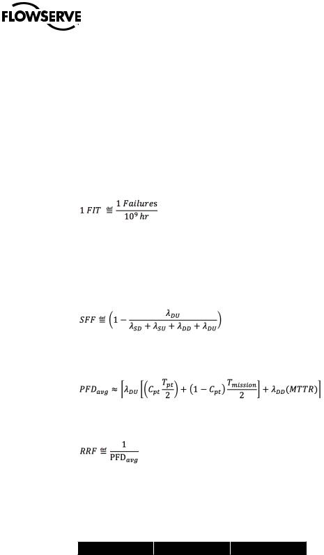
2.5Failures in Time (FIT)
Number of failures in time.
2.6Mean Time to Restoration (MTTR)
Average failure detection time plus average repair time.
2.7SFF
Safe failure fraction.
2.8PFDavg
The average probability of failure on demand for a safety function (approximate).
2.9RRF
Risk reduction factor.
2.10 SIL vs PFDavg vs RFF
Table 1 is based upon “low-demand Mode,” i.e., the safety function is required to be operated no more frequently than twice the proof test period (see 2.4 ).
Table 2.1 - SIL vs PFDavg
SIL |
PFDavg |
|
RFF |
|
4 |
|
… < 10-4 |
|
10,000 to 100,000 |
10-5 |
|
|||
3 |
10-4 |
… < 10-3 |
|
1,000 to 10,000 |
2 |
10-3 |
… < 10-2 |
|
100 to 1000 |
1 |
10-2 |
… < 10-1 |
|
10 to 100 |
8
FLOWSERVE PROPRIETARY INFORMATION
Use or disclosure of this information is subject to the restrictions on the title page of this document

Limitorque MX Electronic Actuator FCD LMENIM2350-01 – 9/13
3 Safety Requirements
3.1 Monitor Relay Annunciation
Any operating mode or self-detected system failure that could prevent the actuator from performing its Safety Instrumented Function on demand from the Safety Instrumented System shall cause the actuator’s monitor relay to de-energize, thus providing indication to the user via the alarm contacts on the monitor relay that the actuator may need to be serviced.
Operating modes Local and Stop shall force the monitor relay to de-energize (indicates that the actuator is not available for demands from remote control wiring).
Loss of power at the actuator terminals shall force the monitor relay to de-energize.
Built-in diagnostic scans shall be automatically performed by the actuator no less frequently than once every 10 seconds.
3.2 Local Control Knobs Sensors
Sensors for local control knobs shall be redundant such that a single sensor failure can be detected by the actuator’s Built-In Self-Test [BIST] system. Self-detected hardware failures of the local control knobs shall force the monitor relay to de-energize. However, while such failures shall be indicated by the monitor relay, the actuator shall be configured such that a demand from the ESD input shall ignore any hardware failures at the local control knobs and shall respond to SIF demands from the SIS.
3.3 ESD Override for Knobs
The actuator should be configured such that ESD demand signals will take priority over local control knob “STOP” and “LOCAL” operating modes.
3.4 The LCD Display May Also Indicate Warnings and Alarms
NOTE: Because the LCD and its drive components may fail, the user must rely solely on the state of the monitor relay for accurate SIF availability status.
3.5 Partial Stroke Test Interval
User should perform the partial stroke test sequence at least once per month during the mission life of the actuator.
9
Use or disclosure of this information is subject to the restrictions on the title page of this document |
flowserve.com |
FLOWSERVE PROPRIETARY INFORMATION |
|

Limitorque MX Electronic Actuator FCD LMENIM2350-01 – 9/13
3.6 Proof Test Interval
User should perform a full stroke proof test sequence at least once per year during the mission life of the actuator.
3.7 Basic Safety Configuration Requirements
Actuator should be configured and wired for emergency operation and partial stroke testing as shown in section 9.4 of this document.
3.8 Optional Emergency Overrides
The user may choose to disable certain actuator protection features such that the actuator may sacrifice itself in order to attempt to achieve the demanded safe state during an emergency.
See “ESD (Emergency Shutdown) Overrides” in the IOM.
NOTE: The actuator warranty shall be voided if any of these protection features are disabled.
3.9 Labeling
Actuators that have been approved for operation in Safety Instrumented Systems shall have a label affixed that indicates its SIL rating.
10
FLOWSERVE PROPRIETARY INFORMATION
Use or disclosure of this information is subject to the restrictions on the title page of this document

Limitorque MX Electronic Actuator FCD LMENIM2350-01 – 9/13
4 Design for Safety
Figure 4.1 - Safety Block Diagram - Basic ESD and PST
|
|
|
|
Monitor Relay |
|
|
|
|
Monitor Relay |
|
Case A B C D Meaning Action De energises? |
Case A B C D Meaning Action De energises? |
|
||||||||
1 |
0001 |
Invalid |
STOP |
Yes |
1 |
0001 |
Invalid |
STOP |
Yes |
|
2 |
0010 |
LOCAL |
|
Yes |
2 |
0010 |
CLOSE |
|
No |
|
3 |
0011 |
Invalid |
STOP |
Yes |
3 |
0011 |
Invalid |
STOP |
Yes |
|
4 |
0100 |
LOCAL |
|
Yes |
4 |
0100 |
CLOSE |
|
No |
|
5 |
0101 |
Invalid |
STOP |
Yes |
5 |
0101 |
Invalid |
STOP |
Yes |
|
6 |
0110 |
Invalid |
STOP |
Yes |
6 |
0110 |
Invalid |
STOP |
Yes |
11 |
7 |
0111 |
STOP |
|
Yes |
7 |
0111 |
STOP |
|
No |
|
8 |
1000 |
Invalid |
STOP |
Yes |
8 |
1000 |
Invalid |
STOP |
Yes |
|
9 |
1001 |
REMOTE |
|
No |
9 |
1001 |
OPEN |
|
No |
|
10 |
1010 |
Invalid |
STOP |
Yes |
10 |
1010 |
Invalid |
STOP |
Yes |
|
11 |
1011 |
Invalid |
STOP |
Yes |
11 |
1011 |
Invalid |
STOP |
Yes |
|
12 |
1100 |
REMOTE |
|
No |
12 |
1100 |
OPEN |
|
No |
|
13 |
1101 |
Invalid |
STOP |
Yes |
13 |
1101 |
Invalid |
STOP |
Yes |
|
14 |
1110 |
Invalid |
STOP |
Yes |
14 |
1110 |
Invalid |
STOP |
Yes |
|
15 |
1111 |
Invalid |
STOP |
Yes |
15 |
1111 |
Invalid |
STOP |
Yes |
|
Use or disclosure of this information is subject to the restrictions on the title page of this document |
|
|
|
|
flowserve.com |
|
||||
FLOWSERVE PROPRIETARY INFORMATION |
|
|
|
|
|
|
|
|
|
|

Limitorque MX Electronic Actuator FCD LMENIM2350-01 – 9/13
4.1 LimiGard™
LimiGard™ is at the heart of the design for safety that is integral to every Limitorque MXa and QX commercial and/or SIL-rated electric actuator.
LimiGard is a patented digital command and monitoring system that employs coded signals throughout and automatically monitors the health of each signal to ensure that no component failure in the signal path can cause the actuator to move unexpectedly.
Motor control signals are redundant in that two healthy signals must be present before the motor will be able to move. Both the enable signal and the direction signals (CW or CCW) must be present and healthy so that the motor will respond to the command. All command signals must also meet the waveform shape specifications to be considered healthy. If the command signal waveform does not meet the frequency and duty cycle specification, or fails to high or low DC voltage values, then no charge can be pumped through the charge pump and the command signal will not be passed to its target contactor coil.
The LimiGard feature also employs a function that can detect when a single output switch is “on.” Normally, zero switches are on when the motor is idle, and two switches are on when the motor is active. Whenever a single switch is on, the LimiGard feature detects that as a fault and alerts the user.
Operating mode signals from the knobs on the local control compartment are also redundant in the sense that there are four sensors to detect three valid knob positions. Each valid knob position requires signals from two of the four sensors. There are only five valid combinations out of the 16 possible sensor signal combinations that will be accepted as valid signals. All other combinations will be detected and reported as “Hardware Fault / Knobs.”
The absolute encoder position sensor also rests within the scope of LimiGard protection. The encoder includes several BIST features for which patents are pending. In particular, each data bit that comprises the resulting position value has been validated by the encoder to ensure that each bit signal transmitter and receiver is healthy. Whenever any data bit is determined to be unreliable or failed, the LimiGard feature alerts the user.
While most LimiGard alerts will be displayed on the digital screen in the window on the control compartment, some failures, such as power loss, CPU failure or LCD failure will make it impossible to show details of the failure on the digital display screen. The user should always rely on the state of the monitor relay, which will always de-energize whenever the actuator is not available to respond to remote demand signals.
Note: Although “Local” and “Stop” operating modes are not failures, the actuator will not normally respond to remote demand signals when it is in one of those modes. Therefore, the monitor relay will de-energize when the actuator is in one of those modes.
Note: For emergency operation, many users will want the actuator to respond to emergency shutdown demand signals, even if the operating mode is Local or Stop, or if some protective feature has been asserted by the actuator (e.g., motor over temperature, hardware fault/knob, hardware fault/encoder). Many such protection features can be overridden by the ESD function. However, by choosing to override the protection features to achieve a safety function at the expense of sacrificing the actuator will void factory warranty.
|
4.2 Optional Safety Add-ons |
|
4.2.1 Fire Protection |
|
A self-sacrificing, fire-resistant coating may be applied to the actuator that will allow the actuator to continue func- |
|
tioning for 30 minutes while immersed in flame. |
12 |
Fire protection has not been included in the calculations for SIL rating of the basic actuator. |
FLOWSERVE PROPRIETARY INFORMATION
Use or disclosure of this information is subject to the restrictions on the title page of this document

Limitorque MX Electronic Actuator FCD LMENIM2350-01 – 9/13
4.2.2 Safety Critical User Wiring
The LimiGard concept can be extended to user wiring as shown in Safety Block Diagram - Enhanced User Wiring (Figure 4.2 below) and configuring the actuator in accordance with subsection 10.5, Custom Input Mode - Momentary ESD/PSESD (Optional).
NOTE: With enhanced PST/ESD configuration, a momentary ESD demand signal will be honored by the actuator, even if user wiring is subsequently destroyed during the emergency event.
Figure 4.2 - Safety Block Diagram - Enhanced User Wiring
|
|
|
|
|
|
|
|
|
|
|
Monitor Relay |
|||
|
Case |
A B C D |
Meaning |
Action |
De energises? |
|||||||||
|
1 |
0001 |
|
Invalid |
STOP |
|
Yes |
|||||||
|
2 |
0010 |
|
LOCAL |
|
|
|
Yes |
||||||
|
3 |
0011 |
|
Invalid |
STOP |
|
Yes |
|||||||
|
4 |
0100 |
|
LOCAL |
|
|
|
Yes |
||||||
|
5 |
0101 |
|
Invalid |
STOP |
|
Yes |
|||||||
|
6 |
0110 |
|
Invalid |
STOP |
|
Yes |
|||||||
|
7 |
0111 |
|
STOP |
|
|
|
Yes |
||||||
|
8 |
1000 |
|
Invalid |
STOP |
|
Yes |
|||||||
|
9 |
1001 |
|
REMOTE |
|
|
|
No |
||||||
|
10 |
1010 |
|
Invalid |
STOP |
|
Yes |
|||||||
|
11 |
1011 |
|
Invalid |
STOP |
|
Yes |
|||||||
|
12 |
1100 |
|
REMOTE |
|
|
|
No |
||||||
|
13 |
1101 |
|
Invalid |
STOP |
|
Yes |
|||||||
|
14 |
1110 |
|
Invalid |
STOP |
|
Yes |
|||||||
|
15 |
1111 |
|
Invalid |
STOP |
|
Yes |
|||||||
|
|
|
|
|
|
|
|
|
|
|
|
|
|
|
|
|
|
|
|
|
|
|
|
|
Monitor Relay |
||
Case |
A B C D |
Meaning |
Action |
De energises? |
||||||||
1 |
|
|
0001 |
|
Invalid |
|
STOP |
|
Yes |
|||
2 |
|
|
0010 |
|
CLOSE |
|
|
|
|
No |
||
3 |
|
|
0011 |
|
Invalid |
|
STOP |
|
Yes |
|||
4 |
|
|
0100 |
|
CLOSE |
|
|
|
|
No |
||
5 |
|
|
0101 |
|
Invalid |
|
STOP |
|
Yes |
|||
6 |
|
|
0110 |
|
Invalid |
|
STOP |
|
Yes |
|||
7 |
|
|
0111 |
|
STOP |
|
|
|
|
No |
||
8 |
|
|
1000 |
|
Invalid |
|
STOP |
|
Yes |
|||
9 |
|
|
1001 |
|
OPEN |
|
|
|
|
No |
||
10 |
|
1010 |
|
Invalid |
|
STOP |
|
Yes |
||||
11 |
|
1011 |
|
Invalid |
|
STOP |
|
Yes |
||||
12 |
|
1100 |
|
OPEN |
|
|
|
|
No |
|||
13 |
|
1101 |
|
Invalid |
|
STOP |
|
Yes |
||||
14 |
|
1110 |
|
Invalid |
|
STOP |
|
Yes |
||||
15 |
|
1111 |
|
Invalid |
|
STOP |
|
Yes |
||||
|
|
|
|
|
|
|
|
|
|
|
|
|
13
Use or disclosure of this information is subject to the restrictions on the title page of this document |
flowserve.com |
FLOWSERVE PROPRIETARY INFORMATION |
|

Limitorque MX Electronic Actuator FCD LMENIM2350-01 – 9/13
5 LimitorqueFunctions MXa Safety
5.1 Emergency Shutdown Open (ESD-Open)
A remote, external ESD signal may be applied to the actuator to move the valve to the OPEN position through predetermined, user-configured shutdown position, overriding existing control signals.
5.2 Emergency Shutdown Close (ESD-Close)
A remote, external ESD signal may be applied to the actuator to move the valve to the CLOSE position through predetermined, user-configured shutdown position, overriding existing control signals.
5.3 Emergency Shutdown ‘Move To’ (ESD-Position)
A remote, external ESD signal may be applied to the actuator to move the valve to a target position through predetermined, user-configured target position, overriding existing control signals.
5.4 Emergency Shutdown Stop (ESD-Stop)
A remote, external ESD signal may be applied to the actuator to stop in place, overriding existing control signals.
5.5 Emergency Shutdown Ignore (ESD-Ignore)
A remote, external ESD signal may be applied to the actuator to ignore, thus remaining responsive to any other existing control signals.
14
FLOWSERVE PROPRIETARY INFORMATION
Use or disclosure of this information is subject to the restrictions on the title page of this document
 Loading...