


|
USER INSTRUCTIONS |
MX/QX Profibus DP / PA Field Unit |
Installation |
FCD LMENIM2336-03 – 12/12 |
Operation |
|
Maintenance |
|
|
Experience In Motion

PB DPV1 / PA Field Unit Installation and Maintenance FCD LMENIM2336-03 – 12/12
Contents
|
1 |
Introduction |
5 |
|
|
|
|
|
|
1.1 Purpose |
5 |
|
|
|
|
|
|
1.2 How to Use this Manual |
5 |
|
|
|
|
|
|
1.3 User Safety |
6 |
|
|
|
|
|
|
1.4 User Knowledge |
6 |
|
|
|
|
|
|
1.5 MX/QX PB System Capabilities and Features |
7 |
|
|
|
|
|
|
1.5.1 General Network Specification |
10 |
|
|
|
|
|
2 System Components and Installation |
12 |
|
|
|
|
|
|
|
2.1 Introduction |
12 |
|
|
|
|
|
|
2.2 Hardware |
13 |
|
|
|
|
|
|
2.2.1 MX/QX Actuator |
14 |
|
|
|
|
|
|
2.2.2 MX/QX PB Field Unit |
14 |
|
|
|
|
|
|
2.2.3 Network Host Station |
15 |
|
|
|
|
|
|
2.2.4 Network Cabling for PROFIBUS DP |
16 |
|
|
|
|
|
|
2.2.5 Network Cabling for PROFIBUS PA |
20 |
|
|
|
|
|
|
2.3 Other Network Components |
23 |
|
|
|
|
|
|
2.4 Site and Network Cable Preparation |
24 |
|
|
|
|
|
|
2.4.1 Site Preparation |
24 |
|
|
|
|
|
|
2.4.2 Network Cable Preparation |
25 |
|
|
|
|
|
|
2.4.3 MX/QX PB Device Installation |
30 |
|
|
|
|
|
|
2.5 MX/QX PB Device Setup |
31 |
|
|
|
|
|
|
2.5.1 Proportional Band |
33 |
|
|
|
|
|
|
2.5.2 Deadband |
33 |
|
|
|
|
|
|
2.5.3 Valve Data |
33 |
|
|
|
|
|
|
2.6 MX/QX PB Device Description, Capabilities and Device Type Manager File Installation |
34 |
|
|
|
|
|
|
2.6.1 MX/QX PB Device Description |
34 |
|
|
|
|
|
|
2.6.2 MX/QX PB Device Type Manager |
34 |
|
|
|
|
|
|
2.7 Installation Verification |
34 |
|
|
|
|
|
|
2.7.1 Network Cabling Installation Verification |
34 |
|
|
|
|
|
|
2.7.2 MX/QX PB Device Installation Verification |
35 |
|
|
|
|
|
|
2.8 Configuration Confirmation |
35 |
|
|
|
|
|
|
2.8.1 Checking Connections |
35 |
|
|
|
|
|
|
2.8.2 View Settings |
35 |
|
|
|
|
|
|
2.8.3 Checking the Normal Display |
36 |
|
|
|
|
|
3 |
Software |
38 |
|
|
|
|
|
|
3.1 PROFIBUS Protocol |
38 |
|
|
|
|
|
|
3.2 PROFIBUS Function, Transducer, and Physical Blocks |
38 |
|
|
|
|
|
|
3.3 Analog Input (AI) Function Block |
41 |
|
|
|
|
|
|
3.4 Analog Output (AO) Function Block |
44 |
|
|
|
|
|
|
3.5 Discrete Input (DI) Function Block |
48 |
|
|
|
|
|
|
3.6 Discrete Output (DO) Function Block |
50 |
|
|
|
|
|
|
3.7 Transducer Block |
52 |
|
|
|
|
|
|
3.8 GSD and Electronic Device Description, and DTM Files |
53 |
|
|
|
|
2 |
4 |
Associated Documents |
54 |
|
|
|
|
|
|
|
|

PB DPV1 / PA Field Unit Installation and Maintenance FCD LMENIM2336-03 – 12/12
5 How to Order Parts |
55 |
|
A Appendix – Wiring Diagrams |
56 |
|
|
|
|
B Appendix – Feature Definitions |
62 |
|
|
|
|
C Appendix – PROFIBUS Function Block |
80 |
|
Glossary |
85 |
|
|
|
|
Tables |
|
|
Table 2.1 – Maximum Segment Length |
17 |
|
|
|
|
Table 2.2 – Total Network Length (with up to nine repeaters) |
17 |
|
Table 2.3 – Recommended PROFIBUS DP Cable Parameters |
17 |
|
|
|
|
Table 2.4 – Recommended PROFIBUS DP Cable Types |
18 |
|
|
|
|
Table 2.5 – Recommended PROFIBUS PA Cable Parameters (Type A – shielded twisted-pair) |
20 |
|
Table 2.6 |
– Recommended PROFIBUS PA Cable Types |
20 |
|
|
|
Table 2.7 |
– Recommended Lengths of PROFIBUS PA Spurs (Stubs) |
21 |
|
|
|
Table 2.8 |
– Details of Terminal Block Cable Assignments |
29 |
Table 3.1 |
– Description of the Function Blocks |
40 |
|
|
|
3
flowserve.com

PB DPV1 / PA Field Unit Installation and Maintenance FCD LMENIM2336-03 – 12/12
Figures
|
Figure 1.1 – Typical PROFIBUS DP Network with DCS or PLC as the Host System |
8 |
|
|
|
|
|
|
Figure 1.1a – Typical PROFIBUS DP Network with Redundancy Option (Single Master) |
9 |
|
|
|
|
|
|
Figure 1.1b – Typical PROFIBUS DP Network with Redundancy Option (Dual Master) |
9 |
|
|
|
|
|
|
Figure 1.2 – Typical PROFIBUS PA Network with DCS or PLC as the Host System |
10 |
|
|
|
|
|
|
Figure 2.1 – MX/QX-05 Actuator |
13 |
|
|
|
|
|
|
Figure 2.2 – MX/QX PB DP Field Unit |
14 |
|
|
|
|
|
|
Figure 2.3 – MX/QX PB PA Field Unit |
15 |
|
|
|
|
|
|
Figure 2.4 – Typical Cycle Time (Each Station with 2 Bytes I/O) |
16 |
|
|
|
|
|
|
Figure 2.5 – Copper PROFIBUS Distance vs. Baud Rate Chart |
18 |
|
|
|
|
|
|
Figure 2.6 – Cable Topologies |
19 |
|
|
|
|
|
|
Figure 2.7 – Use of Shielded Cable in PROFIBUS DP |
19 |
|
|
|
|
|
|
Figure 2.8 – PROFIBUS PA Cable Topologies |
21 |
|
|
|
|
|
|
Figure 2.9 – Use of Shielded Cable in PROFIBUS PA |
22 |
|
|
|
|
|
|
Figure 2.10 – PROFIBUS PA Power Supply |
23 |
|
|
|
|
|
|
Figure 2.11 – PROFIBUS Segments |
24 |
|
|
|
|
|
|
Figure 2.12a – PROFIBUS DP Cable Connections |
25 |
|
|
|
|
|
|
Figure 2.12b – PROFIBUS DP Cable Connections (Redundancy Option with Single Master) |
25 |
|
|
|
|
|
|
Figure 2.12c – PROFIBUS DP Cable Connections (Redundancy Option with Dual Master) |
26 |
|
|
|
|
|
|
Figure 2.13 – PROFIBUS PA Cable Connections to Terminal Blocks |
26 |
|
|
|
|
|
|
Figure 2.14 – Removing Outer Plastic Jacket |
27 |
|
|
|
|
|
|
Figure 2.15 – Separating Cable Parts |
27 |
|
|
|
|
|
|
Figure 2.16 – Stripping Conductors |
28 |
|
|
|
|
|
|
Figure 2.17 – Applying Heat-Shrink Tubing |
28 |
|
|
|
|
|
|
Figure 2.18 – Ring Tongue Connectors |
29 |
|
|
|
|
|
|
Figure 2.19 – Connecting Network Cable to the MX/QX Terminal Block |
30 |
|
|
|
|
|
|
Figure 2.20a – MX/QX PB DP Primary Board Mounted to MX/QX Main Board |
30 |
|
|
|
|
|
|
Figure 2.20b – MX/QX PB DP Primary and Redundant Boards Mounted to MX/QX Main Board |
30 |
|
|
|
|
|
|
Figure 2.21 – MX/QX PB DP Setup Sequence |
31 |
|
|
|
|
|
|
Figure 2.22 – MX/QX PB PA Setup Sequence |
32 |
|
|
|
|
|
|
Figure 2.23 – Normal Display, Field Unit is Communicating with Host |
36 |
|
|
|
|
|
|
Figure 2.24a – No Communications |
36 |
|
|
|
|
|
|
Figure 2.24b – No Communications |
37 |
|
|
|
|
|
|
Figure 2.25 – Hardware Failure, No Communication, Bus Power Lost |
37 |
|
|
|
|
|
|
Figure 3.1 – MX/QX Actuator Block Overview |
39 |
|
|
|
|
|
|
Figure 3.2 – Summary of the Parameters of the Analog Input Function Block |
41 |
|
|
|
|
|
|
Figure 3.3 – Analog Input Block |
42 |
|
|
|
|
|
|
Figure 3.4 – Analog Input Block Scaling and Filtering |
43 |
|
|
|
|
|
|
Figure 3.5 – Summary of the Parameters of the Analog Output Block |
44 |
|
|
|
|
|
|
Figure 3.6 – Analog Output Function Block |
45 |
|
|
|
|
|
|
Figure 3.7 – Analog Output Block Scaling |
47 |
|
|
|
|
|
|
Figure 3.8 – Summary of the Parameters of the Discrete Input Function Blocks |
49 |
|
|
|
|
|
|
Figure 3.9 – Discrete Input Function Block |
49 |
|
|
|
|
|
|
Figure 3.10 – Summary of the Parameters of the Discrete Output Function Block |
50 |
|
|
|
|
|
4 |
Figure 3.11 – Discrete Output Function Block |
51 |
|
|
|
||
Figure 3.12 – PROFIBUS PA Configuration Requirements |
53 |
||
|
|||
|
|
|

PB DPV1 / PA Field Unit Installation and Maintenance FCD LMENIM2336-03 – 12/12
1 Introduction
1.1 Purpose
This manual explains how to install and operate the Flowserve Limitorque MX/QX PROFIBUS field unit, referred to as the MX (Multi-turn)/QX (Quarter-turn) PB (PROFIBUS) field unit. Actuators containing the PB field unit may be connected by shielded twisted-pair, or shielded two-wire cable to form a PROFIBUS communication system network. The name PROFIBUS is derived from Process Fieldbus. The PROFIBUS communication system is a digital, serial, two-way open bus system that supports a variety of communication rates. The MX/QX PB unit supports a communication rate up to 1.5 Mbit/sec. This system allows a network host station such as a distributed control system (DCS) or a programmable logic controller (PLC) to control and monitor the actuators, including the acquisition of status and alarm data from each MX/QX.
1.2 How to Use this Manual
Each section provides the MX/QX PB user with information on installing and operating the MX/QX PB field unit.
Section 1. Introduction The introduction details user safety and knowledge requirements, system capabilities, and features.
Section 2. System Components and Installation The system components section focuses on the description of the PROFIBUS system hardware and software components, and provides details for installing and configuring a field unit.
Section 3. Software The software section provides details regarding the software that the MX/QX PB uses to communicate.
Section 4. |
Associated Documents This section provides a list of documents on related subjects for |
5 |
additional MX/QX and PROFIBUS system information. |
|
|
Section 5. |
How to Order Parts This section provides part numbers and ordering contact |
|
information. |
|
|
flowserve.com

PB DPV1 / PA Field Unit Installation and Maintenance FCD LMENIM2336-03 – 12/12
Appendix A – Wiring Diagram This section contains the detailed wiring connection information for the MX/QX field unit.
Appendix B – Feature Definitions This section contains the Flowserve Limitorque actuator
Transducer Block I/O (Input/Output) channels and parameters.
Appendix C – PROFIBUS Function Block This section contains the PROFIBUS Function Block parameters and descriptions.
Glossary The glossary contains a terminology list of abbreviations, acronyms and their descriptions.
1.3 User Safety
Safety notices in this manual detail precautions the user must take to reduce the risk of personal injury and damage to the equipment. The user must read and be familiar with these instructions before attempting installation, operation, or maintenance. Failure to observe these precautions could result in serious bodily injury, damage to the equipment, warranty void, or operational difficulty. The user must follow all applicable local and state safety regulations.
Safety notices are presented in this manual in three forms:
cWARNING: Refers to personal safety and alerts the user to potential danger. Failure to follow warning notices could result in personal injury or death.
aCAUTION: Direct the user’s attention to general precautions that, if not followed, could result in personal injury and/or equipment damage.
NOTE: Highlights information critical to the user’s understanding of the actuator’s installation and operation.
1.4 User Knowledge
It is recommended that the user read this manual in its entirety before the MX/QX PB field unit is installed and operated.
The user needs to have a fundamental knowledge of electronics and an understanding of valve actuators and digital control systems. Refer to the Glossary for information regarding the terms used throughout this manual.
The following websites have documents on PROFIBUS and electric actuators:
www.PROFIBUS.com
www.flowserve.com
www.iec.ch
For PROFIBUS technology and cabling information, refer to the following documents:
6
• PROFIBUS DP Specification, IEC 61158 Type 3 and IEC 61784.
• PROFIBUS Profile – PROFIBUS PA – Profile for Process Control Devices, Version 3.02, November 2008, PROFIBUS International Order No. 3.042.

PB DPV1 / PA Field Unit Installation and Maintenance FCD LMENIM2336-03 – 12/12
•Installation Guidelines for PROFIBUS – FMS/DP Version 1.0, PROFIBUS International Order No. 2.112.
•Profibus Installation Guideline For Cabling and Assembly, Version 1.0.6, PROFIBUS International Order No. 8.022.
•Profibus Installation Guideline For Commissioning, Version 1.0.2, PROFIBUS International Order No. 8.032.
•Technical Guideline: PROFIBUS PA User & Installation Guideline, Version 2.2, February 2003.
•PROFIBUS Specification - Slave Redundancy Version 1.2, PROFIBUS International Order No. 2.212, November 2004.
1.5 MX/QX PB System Capabilities and Features
Flowserve Limitorque’s MX/QX PROFIBUS (PB) field unit conforms to the open fieldbus standard EN50170. It is suitable for use on PROFIBUS and uses a twisted-pair or two-conductor shielded cable for connection to the network. A PROFIBUS device is an intelligent device within the actuator that can send multiple variables to the control system over a high-resolution and distortion-free digital communication network. The device provides control and self-test capabilities, which allow abnormal conditions to be easily and immediately identified before an unplanned shutdown.
The MX/QX PB unit may command its actuator to: open, stop, close, move to a set position, perform an emergency shutdown operation, read and control relays, monitor analog inputs and position, and monitor modes and alarms. Commands to the unit come over the network from the master network host station, which may be a Personal Computer (PC), Distributed Control System (DCS), Programmable Logic Controller (PLC), or some other microprocessor-based device. The master is defined as an active network node which means that it has addressing, and read and write privileges to slave devices that are assigned to it.
Additional features and capabilities are:
•The system reduces the cost of wiring and installation by using existing wiring and multi-drop connections, if it meets PROFIBUS requirements. It is also possible to have more than one PROFIBUS communication network on the same cabling.
•Multiple-master operations through the use of the PROFIBUS token being passed between masters (active nodes). Each master has its own set of slaves and may only write to those slaves.
•Master-slave operations where the master, active node, has the right to address, and send or fetch messages from the slaves (passive nodes).
•The devices are interoperable, as devices from different suppliers communicate with one another on the same network.
The PROFIBUS communication system supports up to 32 devices per segment, with up to 126 addressable devices with the use of repeaters.
Segmentation is used for the following reasons:
•Isolation is desired between two areas or buildings.
•Media conversion (copper to fiber or fiber to copper) is desired.
• The maximum of 32 nodes has been reached (31 + repeater). |
7 |
|
•The maximum distance has been reached.
•It is desirable to “reform” the signal to full voltage levels (noisy environment).
flowserve.com
PB DPV1 / PA Field Unit Installation and Maintenance FCD LMENIM2336-03 – 12/12
The devices used to create a segment are Repeaters for copper networks, Optical Link Modules for glass or plastic-coated glass fiber-optic networks, and Optical Bus Terminals for plastic fiber-optic networks. Each of these devices provides either electrical or optical isolation between segments.
The MX/QX PB field unit fits in the actuator in the sealed electrical housing compartment. There are two different communication board options for the MX/QX PB field unit: MX/QX PB DP, which supports PROFIBUS DP (Decentralized Periphery) RS-485 physical layer and MX/QX PB PA, which
supports PROFIBUS PA (Process Automation) IEC 1158 physical layer. The MX/QX PB DP field unit is available with Flying and System Redundancy.
PROFIBUS DP ensures high-speed data transmission of user data, and is designed especially for communication between a master host station and distributed devices at the field level.
PROFIBUS PA uses the expanded PROFIBUS DP protocol for data transmission and implements the PA profile that specifies the characteristics of the field device. This transmission technique ensures intrinsic safety and powers the field devices over the bus. PROFIBUS PA is designed for high-speed and reliable communications, with the ability to link sensors and actuators to a common fieldbus line, even in potentially explosive areas.
PROFIBUS PA devices can be integrated into PROFIBUS DP networks using segment couplers.
The adjustments to the MX/QX PB settings may be made locally at the actuator and over the PROFIBUS network using a DPV1 network configuration tool.
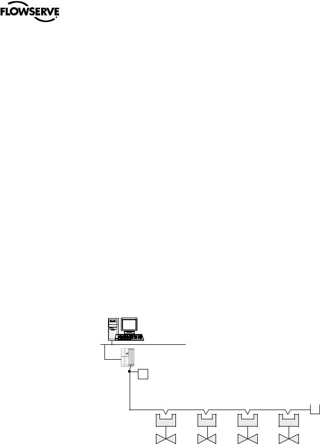
A typical MX/QX PB DP system is shown in Figure 1.1 in a Master/Slave Configuration, Figure 1.1a shows a typical PROFIBUS DP network with redundancy option in a single master configuration, Figure 1.1b shows a typical PROFIBUS DP network with redundancy option in a dual master configuration, and Figure 1.2 shows a typical MX/QX PB PA system.
Figure 1.1 – Typical PROFIBUS DP Network with DCS or PLC as the Host System
Distributed Control
System (Host)
Control Highway
PROFIBUS DP-V1
Interface
T Terminator
PB |
Actuator |
Power for the fieldbus devices and cable shield grounding are discussed in Sections 2.4 and 2.5.
PROFIBUS DP Network |
Terminator |
||
|
|
|
|
T
PB |
PB |
PB |
Actuator |
Actuator |
Actuator |
8
PB DPV1 / PA Field Unit Installation and Maintenance FCD LMENIM2336-03 – 12/12
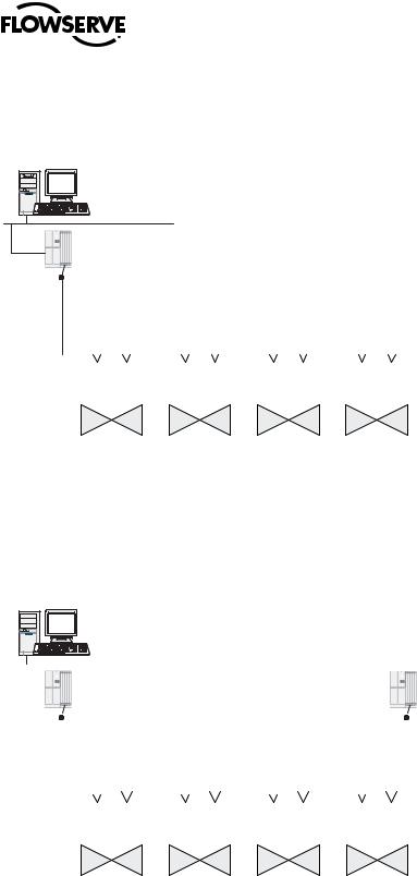
Figure 1.1a – Typical PROFIBUS DP Network with Redundancy Option (Single Master)
Distributed Control
System (Host)
Control Highway
PROFIBUS DP-V1
Interface
|
T |
Terminator |
|
|
|
|
|
|
|
|
|
|
|
|
|
|
PROFIBUS DP Network |
|
|
|
|
|
|
|
Terminator |
|||||||||||
|
|
|
|
|
|
|
|
|
|
|
|
|
|
|
|
|
|
|
|
|
||||||||||
|
|
|
|
|
|
|
|
|
|
|
|
|
|
|
|
|
|
|
|
|
|
|
|
|
|
|
|
|
T |
|
|
|
|
|
|
|
|
|
|
|
|
|
|
|
|
|
|
|
|
|
|
|
|
|
|
|
|
||||
|
PBDP-A |
PBDP-B |
|
PBDP-A |
PBDP-B |
|
PBDP-A |
PBDP-B |
|
PBDP-A |
PBDP-B |
|
|
|
||||||||||||||||
|
|
Actuator |
|
|
Actuator |
|
|
Actuator |
|
|
Actuator |
|
|
|
||||||||||||||||
|
|
|
|
|
|
|
|
|
|
|
|
|
|
|
|
|
|
|
|
|
|
|
|
|
|
|
|
|
|
|
Figure 1.1b – Typical PROFIBUS DP Network with Redundancy Option (Dual Master)
Distributed Control
System (Host)
Control Highway
|
|
|
|
PROFIBUS DP-V1 |
|
|
|
|
|
|
|
|
|
|
|
|
PROFIBUS DP-V1 |
|
||||||||||||||||||||
|
|
|
|
Interface-1 |
|
|
|
|
|
|
|
|
|
|
|
|
Interface-2 |
|
|
|
|
|||||||||||||||||
|
|
|
|
|
|
|
|
|
|
|
|
|
|
|
|
|
|
|||||||||||||||||||||
|
|
|
|
|
|
|
|
|
|
|
|
|
|
|
|
|
|
|
|
|
|
|
|
|
|
|
|
|
|
|
|
|
|
|||||
|
|
|
|
T |
Terminator |
|
|
|
|
|
|
|
|
|
|
|
|
|
Terminator |
T |
|
|
|
|
|
|
|
|
||||||||||
|
|
|
|
|
|
|
|
|
|
|
|
|
|
|
|
|
|
|
|
|
|
|
|
|
|
|
|
|
|
|
|
|
|
|
|
|
||
|
|
|
Terminator |
|
|
|
|
|
|
|
|
|
|
|
|
|
|
|
|
|
|
|
|
|
|
Terminator |
||||||||||||
|
|
|
|
|
|
|
|
|
|
|
|
|
|
|
|
|
|
|
|
|
|
|
|
|
|
|
|
|
|
|
|
|
||||||
|
|
|
|
T |
|
|
|
|
|
|
|
PROFIBUS DP Network |
|
|
|
|
|
|
|
|
|
|
|
T |
|
|
||||||||||||
|
|
|
|
|
|
|
|
|
|
|
|
|
|
|
|
|
|
|
|
|
|
|
|
|
|
|
|
|
||||||||||
|
|
|
|
|
|
|
|
|
|
|
|
|
|
|
|
|
|
|
|
|
|
|
|
|
|
|
|
|
|
|
|
|
|
|
|
|
|
|
|
|
|
|
|
|
|
|
|
|
|
|
|
|
|
|
|
|
|
|
|
|
|
|
|
|
|
|
|
|
|
|
|
|
|||||
|
|
|
|
PBDP-A |
PBDP-B |
|
PBDP-A |
PBDP-B |
|
PBDP-A |
PBDP-B |
|
PBDP-A |
PBDP-B |
|
|
|
|
|
|
||||||||||||||||||
|
|
|
|
|
Actuator |
|
|
Actuator |
|
|
Actuator |
|
|
Actuator |
|
|
|
|
|
|
||||||||||||||||||
|
|
|
|
|
|
|
|
|
|
|
|
|
|
|
|
|
|
|
|
|
|
|
|
|
|
|
|
|
|
|
|
|
|
|
|
|
|
|
9
flowserve.com
PB DPV1 / PA Field Unit Installation and Maintenance FCD LMENIM2336-03 – 12/12
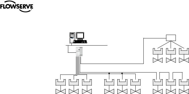
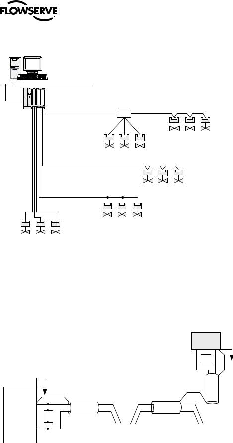
Figure 1.2 – Typical PROFIBUS PA Network with DCS or PLC as the Host System
Distributed Control
System (Host)
Control Highway
PROFIBUS PA
Interface
Power for the fieldbus devices and cable shield grounding are discussed in Sections 2.4 and 2.5.
Junction Box
PA |
PA |
PA |
Actuator |
Actuator |
Actuator |
Tree
PA |
Actuator |
PA |
Actuator |
PA |
Actuator |
PA |
Actuator |
PA |
Actuator |
PA |
Actuator |
PA |
Actuator |
PA |
Actuator |
PA |
Actuator |
Point to Point |
Bus with spurs (or drops) |
Daisy Chain |
1.5.1 General Network Specification
System Specifications:
•Communicates using the PROFIBUS DP or PROFIBUS PA protocol.
•PROFIBUS DP is V1 compliant.
•Employs high-speed communication.
•Complies with EN50170 fieldbus standard.
•PA Physical Layer with IEC1158-2.
•DP Physical Layer with RS-485.
Network Specification:
Several topologies are available including point-to-point, bus, tree, ring, or a combination of these.
Network features include:
•PROFIBUS DP high-speed communications up to 1.5 Mbit/sec.
•PROFIBUS PA communications are 31.25kbits/sec (segment coupler side).
•Master/slave communications.
•Multiple-master network systems.
•Redundant PROFIBUS DP with single or multiple-master communications.
MX/QX Field Unit Specification:
The field unit mounts inside the actuator, is software controlled, and has the following features:
•Input and Output Function Blocks.
•Device descriptions – describes device and parameters.
•Network communication – compliant with EN50170.
•Configurable by user – locally and via network.
10
PB DPV1 / PA Field Unit Installation and Maintenance FCD LMENIM2336-03 – 12/12
PROFIBUS Master Specification
The PROFIBUS master is the network system host, and can be a PC, DCS, PLC, or some other microprocessor-based device. The master is defined as the network node that has addressing, and read/write privileges to slave devices that are assigned to it. A PROFIBUS network can have more than one master, but one, and only one, token is active at a given time. The token provides the right to access the transmission medium, as is passed between the active nodes (masters) with a token telegram. The master host station acts as the bus arbiter, and does the following:
•Recognizes and adds new devices on the link.
•Removes non-responsive devices from the link.
•Distributes a priority-driven token for unscheduled cyclic transmissions between masters.
•Ensures cyclic data transferred on a periodic basis.
•Issues requests for process data from the field devices.
•Issues commands to the field devices.
High Speed Data Exchange – Startup Sequence
•Power ON / Reset – Power on / Reset of master or slave.
•Parameterization – download of parameters into the field device (selected during configuration by the user).
•I/O Configuration – download of I/O configuration into the field device (selected during configuration by the user).
•Data Exchange – cyclic data exchange (I/O Data) and field device reports diagnostics.
NOTE: In the application profile definition, only Function Blocks may have cyclic parameters. Physical Blocks and Transducer Blocks do not have cyclic parameters. PROFIBUS DP/V1 is part of the requirement to access Acyclic parameters through the Function Block specification and is composed of a slot number and an index number. Acyclic services are performed between two data exchange cycles. A PROFIBUS Class 2 Master is required for acyclic data exchange (Function Blocks). An Electronic Device Descriptor File is used in the configuration tool of the Master to gain access to the Function Block parameters (refer to Chapter 3, Software).
Device Configuration Tool Requirements
Generally, the device configuration tool can be executed independently of the control system configuration tool. The general requirements are as follows:
•A PROFIBUS DP or PA network is inserted as an object of a control system project (or independent project).
•Within that network, a device is logically attached along with object name, PROFIBUS DP/PA address, and how many objects are to be attached.
•Editing this device will allow the user to select the type of device (actuator, sensor, etc.).
•The configuration tool will then display the extended parameters with initial values.
•These parameters may be uploaded from the device to display the actual values (if a network connection is possible).
•New values can be entered and then downloaded to the device through the network connection.
•There will also be a method for monitoring the online parameter values.
11
flowserve.com

PB DPV1 / PA Field Unit Installation and Maintenance FCD LMENIM2336-03 – 12/12
2 Systemand InstallationComponents
2.1 Introduction
This section is an overview of the components used in the PROFIBUS system and their integration with the MX/QX actuator. The MX/QX PB field unit is installed in the control compartment of the actuator as shown in Figures 2.1a and 2.1b. The PROFIBUS network cable from the host control station connects to the fieldbus unit at the actuator terminal block.
The Network Cabling section of this chapter is broken into two sections; PROFIBUS DP and
PROFIBUS PA.
Refer to Appendix A for detailed wiring connections.
12

|
|
|
PB DPV1 / PA Field Unit Installation and Maintenance FCD LMENIM2336-03 – 12/12 |
|
|
2.2 Hardware |
|
|
|
|
Figure 2.1a – MX-05 Actuator |
|
|
Figure 2.1b – QX-05 Actuator |
|
|
|
|
10 |
|
|
|
1 |
3 |
|
|
|
|
|
|
|
|
13 |
|
|
3 |
|
2 |
2 |
|
|
|
|
|
|
12 |
|
|
|
|
11 |
|
|
|
|
10 |
|
5 |
|
|
|
4 |
|
|
|
|
5 |
12 |
|
|
|
|
|
|
9 |
8 7 |
|
6 |
1 |
|
|
7 |
||
|
|
|
|
6 |
|
|
|
|
4 |
|
|
|
|
9 |
|
11 |
|
|
9 |
|
|
|
|
|
|
|
|
|
9 |
|
|
|
|
OPTIONAL |
|
2 |
3 |
|
15 |
|
|
14 |
|
3 |
|
|
|
|
8 |
Item |
Description |
|
Item |
|
1 |
Handwheel |
|
1 |
Handwheel |
2 |
Declutch lever |
|
2 |
Declutch lever (QX-05) |
3 |
Oil fills (dotted arrow depicts fill on declutch side) |
|
3 |
Oil fill |
4 |
Controls compartment (field unit location) |
|
4 |
Controls cover |
5 |
LCD display |
|
5 |
LCD display |
6 |
Control knobs |
|
6 |
Control knob |
7 |
Ground lug |
|
7 |
Ground lug |
8 |
Thrust/torque base |
|
8 |
Baseplate |
9 |
Conduit entries |
|
9 |
Conduit entry |
10 |
Terminal compartment |
|
10 |
Terminal compartment |
11 |
Electric motor |
|
11 |
Motor |
12 |
Nameplate |
|
12 |
Certification nameplate |
13Tag nameplate
14Oil plug
15 |
Stem nut stops |
13 |
flowserve.com

PB DPV1 / PA Field Unit Installation and Maintenance FCD LMENIM2336-03 – 12/12
2.2.1 MX and QX Actuators
The MX and QX actuators are designed for operation of ON-OFF and modulating valve applications. The MX is a multi-turn actuator, while the QX is a quarter-turn actuator.
Both the MX and QX include the following features:
•Non-intrusive setup.
•Separately sealed terminal compartment.
•Unique absolute encoder for valve position sensing (no battery required).
•32-character LCD for indication and calibration.
•Enhanced electronic control, monitoring, and diagnostic capabilities with Built-In Self Test (BIST) and LimiGard™ technology.
NOTE: Recommended storage procedures are detailed in the MX and QX Maintenance and Spare Parts Manual LMENIM2314 and LMENIM3314 respectively. Failure to comply with recommended procedures will void the warranty. For longer-term storage, contact Flowserve for procedure and recommendations.
2.2.2 MX/QX PB Field Unit
The MX/QX PB field unit interface board is installed in the actuator controls compartment (Figure 2.1). The MX/QX PB DP version is shown in Figure 2.2, and the MX/QX PB PA version is shown in Figure 2.3. Each unit permits the actuator to be controlled as a slave by one or more master host stations over their respective PROFIBUS network. The MX/QX PB DP version supports two forms of redundancy when two PB DP field unit boards are installed in a single actuator:
a.Flying redundancy provides slave hardware redundancy in the form of an active and standby PB DP field unit installed in each actuator. This form is commonly utilized in applications where a single master is present.
b.System redundancy provides for both slave hardware redundancy, in the form of an active and standby PB field unit installed in each actuator, and cable redundancy in the form of dual masters connected to the active and standby PB DP field units.
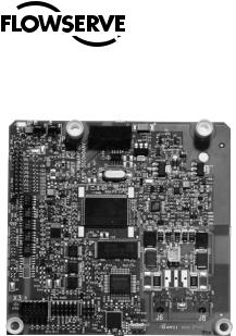
Figure 2.2 – MX/QX PB DP Field Unit
14
Note: Field unit board jumpers, JP1 and JP2, are set to “A” position on Primary board and “B” position on Redundant board.
PB DPV1 / PA Field Unit Installation and Maintenance FCD LMENIM2336-03 – 12/12
Figure 2.3 – MX/QX PB PA Field Unit
The following commands and feedback information are transmitted through this unit:
•OPEN, CLOSE, and STOP commands.
•ESD (Emergency Shutdown) commands.
•Go-to-position commands.
•Redundancy switch-over commands (Profibus DP Redundancy option).
•Position feedback.
•Actuator status, alarm, and diagnostic messages.
•User analog input feedback.
•Discrete input feedback.
•Discrete output relays.
2.2.3 Network Host Station
The PROFIBUS master is considered to be the network host station, which is typically a DCS, PC, PLC or other microprocessor-based PROFIBUS-compliant device. In a mono-master network, the network host device is the only active network node. This is common in a standard Master-Slave PROFIBUS network. In a multi-master network, there are two or more active nodes. This is managed in a token ring, where the token, a uniquely structured message, circulates continuously among the active network nodes. In the case of multiple Masters, only one Master has read/write privileges to its Slaves (passive nodes) at any one time, and the control token is passed continuously in ascending order to all other active network nodes.
2.2.3.1 Token Bus and Token Passing in a Multi-Master Network
During the bus initialization and startup, the bus access control creates the token ring by recognizing the active network nodes in ascending order. The bus access control automatically determines the addresses of all active nodes on the bus, and records them together with its own node address, creating a List of Active Stations. The Lowest Station Address (LSA) begins with the active token, allowing it to fetch and send data messages to its passive slaves (referred to as polling). At completion of its request frame (polling telegram), and acknowledgement or response frame returned from the slave, the token is passed to the Next Station (NS) with a token telegram. The active node from which the node was passed is called the Previous Station (PS). This continues until the token is being passed from the Highest Station Address (HSA). At completion of the HSA polling telegram, the token is passed to the LSA. The List of Active Stations is required during network operation to remove a faulty active node, or to add a node, without disturbing data on the bus.
15
flowserve.com

PB DPV1 / PA Field Unit Installation and Maintenance FCD LMENIM2336-03 – 12/12
2.2.3.2 Token Rotation Time
The time required for the rotation of the token to all active nodes is the token rotation time. The Time Target Rotation (TTR) is adjustable, and is used to specify the maximum allowed time of one rotation.
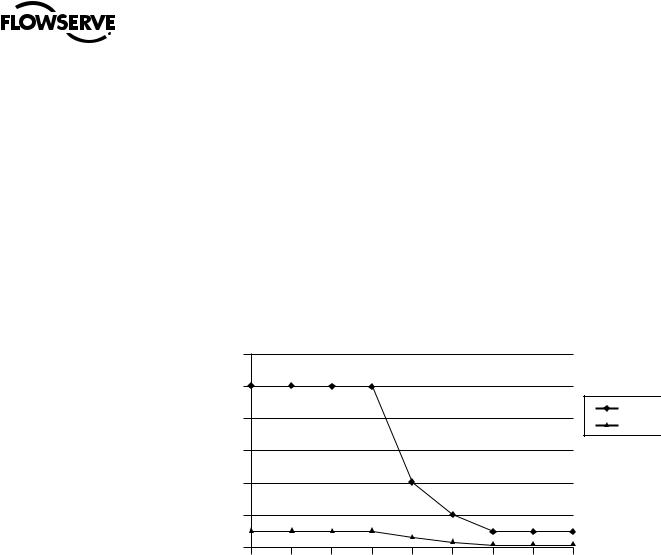
2.2.3.3 Bus Cycle Time
Based on the number of slaves attached to each master and the amount of data to be transferred, a Bus Cycle Time is calculated by the master. This is the amount of time required for a master to poll all slaves. This, along with the Token Rotation Time, makes PROFIBUS network access deterministic.
Figure 2.4 – Typical Cycle Time (Each Station with 2 Bytes I/O)
|
20.0 |
|
|
|
|
|
18.0 |
|
|
|
|
|
16.0 |
|
1.5 MBaud |
|
|
|
|
|
|
|
|
|
14.0 |
|
500 kBaud |
14.1 |
|
(ms) |
|
|
|
|
|
12.0 |
|
|
|
|
|
Time |
10.0 |
|
7.7 |
|
|
|
|
|
|
||
Cycle |
8.0 |
|
|
|
|
|
|
|
8.8 |
||
|
|
|
|
||
|
6.0 |
4.6 |
|
6.1 |
|
|
|
|
|
||
|
4.0 |
|
|
|
|
|
2.0 |
|
|
|
|
|
2.0 |
3.3 |
|
|
|
|
|
|
|
||
|
|
2.0 |
|
|
|
|
|
0.9 |
|
|
|
|
0.0 |
|
|
|
|
|
|
|
|
|
|
|
1 |
5 |
10 |
20 |
30 |
Number of Slaves
2.2.4 Network Cabling for PROFIBIS DP
Network cabling should be in accordance with PROFIBUS Decentralized Periphery (DP) guidelines. To achieve immunity to electromagnetic interference, ensuring high data integrity, certain cables and guidelines are recommended. Additionally, the following items should be taken into account when planning the network:
•Transmission rate – Within a network, only one transmission rate can be used; the MX/QX PB DP works at baud rates up to 1.5 Mbps.
•The level of Master and Slave redundancy, if any.
•The required number of nodes.
•The type of network components needed – terminals, connectors, connecting cables, termination.
•The type of cable to be used and its characteristics.
•The number of segments and/or repeaters.
•The overall span of the network – adding repeaters and long cable lengths can increase transmission time.
•Cable termination – active termination resistors are required at the ends of all segments.
16 |
In general, the following rules apply for PROFIBUS networks: |
|
•The higher the baud rate, the shorter the distance allowed between nodes.
•The higher the baud rate, the shorter the maximum distance of a segment.
•The higher the baud rate, the shorter the maximum distance of an entire network.

PB DPV1 / PA Field Unit Installation and Maintenance FCD LMENIM2336-03 – 12/12
These distance rules (or limitations) are based on the physical characteristics of the RS-485 topology and are not a limitation of the PROFIBUS protocol. If the distance required between two stations or the total network distance is greater than allowed by the PROFIBUS specifications for copper cable, a conversion to fiber-optic cable may be required. Figure 2.5 shows the baud rate versus copper cable distance using PROFIBUS.
Table 2.1 provides the guidelines for maximum segment length versus baud rate.
Table 2.1 – Maximum Segment Length
Baud Rate |
9600 to 187.5K |
500K |
|
1.5M |
Maximum Segment Length (meters) |
|
400 |
|
200 |
1,000 |
|
|||
|
|
|
|
|
Table 2.2 provides the guidelines for maximum network length versus baud rate (assuming the use of up to 9 repeaters).
Table 2.2 – Total Network Length (with up to nine repeaters)
Baud Rate |
9600 to 187.5K |
500K |
|
1.5M |
Total Network Length (meters) |
|
4,000 |
|
2,000 |
10,000 |
|
|||
|
|
|
|
|
NOTE: The maximum lengths are estimates and depend on the condition of the actual cable.
Tables 2.3 and 2.4 detail the various types of cable which can be used for network cabling. For additional guidelines, see the following publications:
•PROFIBUS Networks SIMATIC NET 6GK1970-5CA20-0AA1.
•PROFIBUS Technical Guideline for PROFIBUS-DP/FMS, Version 1.0, September 1998; PROFIBUS Guideline, Order No. 2.112.
There are different types of electrical data transfer cables:
•Standard bus cable.
•Standard bus cable with halogen-free sheath (type FRNC).
•Cable with PE sheath for use in the food and drug manufacturing industries.
•Direct buried cable with additional protective sheath for buried service.
•Trailing cable – This is a special cable type which is used where parts of the machine move occasionally or continuously.
•Festooned cable – Comparable to a trailing cable, but has an additional strain relief element.
NOTE: Cable must meet the requirements as listed in table 2.3 to ensure reliable network communications.
Table 2.3 – Recommended PROFIBUS DP Cable Parameters
Characteristic impedence at 3-20 MHz (ohms) |
135-165 |
|
|
Operating capacitance (pF/m) |
< 30 |
|
|
Loop resistance (ohms/km) |
≤ 110 |
|
|
Core diameter (mm) |
> 0.64 |
|
|
Core cross-section (mm2) |
> 0.34 |
17
flowserve.com
PB DPV1 / PA Field Unit Installation and Maintenance |
FCD LMENIM2336-03 – 12/12 |
|
Table 2.4 – Recommended PROFIBUS DP Cable Types |
|
|
|
|
|
FC Standard Cable (Siemens AG) |
|
6XV1 830-0EH10 |
|
|
|
FRNC Cable (Siemens AG) |
|
6XV1 830-0CH10 |
|
|
|
FC Food Cable (Siemens AG) |
|
6XV1 830-0GH10 |
|
|
|
FC Ground Cable (Siemens AG) |
|
6XV1 830-3FH10 |
|
|
|
FC Trailing Cable (Siemens AG) |
|
6XV1 830-3EH10 |
|
|
|
Festoon Cable (Siemens AG) |
|
6XV1 830-3GH10 |
|
|
|
PROFIBUS Data Cable (Belden Wire and Cable) |
|
3079A/3076F |
|
|
|
PROFIBUS DP Cable (Moeller GmbH) |
|
ZB4-900-KB1 |
|
|
|
PROFIBUS DP Cable (Kerpenwerk GmbH) |
|
7422/7436 |
|
|
|
PROFIBUS DP Cable (ABB Automation GmbH) |
|
NDC110-NO |
|
|
|
Figure 2.5 – Copper PROFIBUS Distance vs. Baud Rate Chart |
|
|
|
|||||||
|
12,000 |
|
|
|
|
|
|
|
|
|
|
10,000 |
|
|
|
|
|
|
|
|
|
|
|
|
|
|
|
|
|
|
|
Network |
|
8,000 |
|
|
|
|
|
|
|
|
Segment |
|
|
|
|
|
|
|
|
|
|
|
(m) |
6,000 |
|
|
|
|
|
|
|
|
|
Distance |
4,000 |
|
|
|
|
|
|
|
|
|
|
|
|
|
|
|
|
|
|
|
|
|
2,000 |
1,000 |
1,000 |
1,000 |
1,000 |
400 |
|
|
1,000 |
1,000 |
|
|
|
|
|
|
200 |
100 |
100 |
100 |
|
|
0 |
|
|
|
|
|
||||
|
|
|
|
|
|
|
|
|
|
|
|
|
9.6 |
19.2 |
93.75 |
187.5 |
500 |
1,500 |
3,000 |
6,000 |
12,000 |
Baud Rate (kBaud)
There are several topologies available for both redundant and non-redundant PROFIBUS networks:
•Point-to-point – A single cable from master to slave.
•Daisy chain – A single cable daisy chained in and out of each field unit device. End of segment devices only have one incoming cable.
•Tree – Cables and electronic devices (such as repeaters or link modules) are used to branch out from different points.
•Ring – Often implemented with fiber-optic cable which forms a circle or ring when used with Optical Link Modules. This topology yields redundancy so that any single component fault or cable break does not affect the network (except for the component).
•Combination of the above.
NOTE: Bus with Spurs, also referred to as stub lines, are not recommended by PROFIBUS as they can create parallel resistance and cause disturbances and reflections on the main trunk or bus line.
18
PB DPV1 / PA Field Unit Installation and Maintenance FCD LMENIM2336-03 – 12/12
Figure 2.6 – Cable Topologies
Distributed Control
System (Host)
Network |
|
PROFIBUS |
|
Interface |
Repeater |
|
|
|
Tree |
Schematic topology: Details such as terminators and power supplies not shown
Daisy Chain
Daisy Chain
Bus with spurs (or drops)
Point-to-point
2.2.4.1 Cable Shielding and Grounding for PROFIBUS DP
For best performance, PROFIBUS DP cables should be shielded. Per PROFIBUS Technical Guidelines, the cable shield should be connected at the beginning and end of the segment. Alternatively, a 10-12 AWG ground wire may be run to each MX/QX.
In Figure 2.7, the grounding point is shown at the junction of the field devices and at each field device.
Figure 2.7 – Use of Shielded Cable in PROFIBUS DP
Field
Device

 T
T 

PROFIBUS T
Interface
|
|
|
|
|
Field |
|
Field |
||
Device |
|
Device |
||
|
|
|
|
|
19
flowserve.com

PB DPV1 / PA Field Unit Installation and Maintenance FCD LMENIM2336-03 – 12/12
2.2.5 Network Cabling for PROFIBUS PA
Network cabling should be in accordance with PROFIBUS Process Automation (PA) guidelines using twisted-pair shielded cable. The data line is normally also used to supply power to the field devices. PROFIBUS PA is a combination of the PROFIBUS-DP V1 protocol and the IEC 61158-2 transmission technique.
The following items should be taken into account when planning the network:
•Transmission rate – Within a network, only one transmission rate can be used; typical restrictions of PA are 31.25kbits/sec.
•The required number of nodes.
•The type of network components needed – Terminals, connectors, connecting cables, termination.
•The type of cable to be used and its characteristics.
•The number of segments and/or repeaters.
•The overall span of the network – Adding repeaters and long cable lengths can increase transmission time.
•Cable termination – Active termination resistors are required at the ends of all segments.
Tables 2.5 and 2.6 detail the recommended cable parameters and various types of cable that can be used for network cabling. For additional guidelines, see the following publications:
• PROFIBUS Networks SIMATIC NET |
6GK1970-5CA20-0AA1 |
•Technical Guideline – PROFIBUS PA User and Installation Guideline Version 2.2 February 2003, PROFIBUS Guideline Order No. 2.092
Table 2.5 – Recommended PROFIBUS PA Cable Parameters (Type A – shielded twisted-pair)
Characteristic impedence |
100 ohms ±20% |
|
|
Maximum capacitance |
2 nF/km |
|
|
Loop resistance |
44 ohms/km |
|
|
Conductor cross-sectional area |
0.8 mm2 (AWG 18) |
Maximum length of network (including spurs) |
1900 m |
|
|
Table 2.6 – Recommended PROFIBUS PA Cable Types
PA, Ex and Non-Ex |
NPC080-NO |
|
(ABB Automation Products GmbH) |
||
|
||
|
|
|
PA, Ex and Non-Ex |
NPC150-NO |
|
(ABB Automation Products GmbH) |
||
|
||
|
|
|
PROFIBUS FC Process Cable (Siemens AG) |
6XV1 830-5.H10 |
|
|
|
|
PROFIBUS Data Cable (Beldon Wire & Cable) |
3079A & 3076F |
|
|
|
|
UNITRONICS Bus PA (Lapp Kabel GmbH) |
2170 235 1x2x1.0 |
|
|
|
20
PB DPV1 / PA Field Unit Installation and Maintenance FCD LMENIM2336-03 – 12/12
Table 2.7 – Recommended Lengths of PROFIBUS PA Spurs (Stubs)
Number of Spur |
Length of Spur Cable |
Length of Spur Cable |
Cables |
Intrinsically Safe (m) |
Non-Intrinsically Safe (m) |
19 to 24 |
|
30 |
30 |
||
|
|
|
15 to 18 |
30 |
60 |
|
|
|
13 to 14 |
30 |
90 |
|
|
|
1 to 12 |
30 |
120 |
|
|
|
NOTE: The maximum lengths are estimates and depend on the condition of the actual cable.
There are several topologies for PROFIBUS networks:
•Daisy Chain – A single cable daisy chained in and out of each device. End devices only have one cable.
•Tree – Cables and electronic devices (such as repeaters or link modules) are used to branch out from different points.
•Star – Similar to a Tree configuration but the cables all originate from one centralized point that is comprised of electronic devices (such as repeaters or link modules).
• Combination of the above.
Figure 2.8 – PROFIBUS PA Cable Topologies
Distributed Control
System (Host)
Control Highway
Schematic topology: Details such
as terminators and power supplies not shown
|
|
PROFIBUS |
Junction |
||||
|
|
Interface |
|||||
|
|
|
|
Box |
|||
|
|
|
|
|
|||
|
|
|
|
|
|
|
|
|
|
|
|
|
|
|
|
|
|
|
|
|
|
|
|
|
|
|
|
|
|
|
|
|
|
|
|
|
|
|
|
|
|
|
|
|
|
|
|
Tree
Daisy Chain
Bus with spurs (or drops)
Point-to-point
21
flowserve.com
PB DPV1 / PA Field Unit Installation and Maintenance FCD LMENIM2336-03 – 12/12
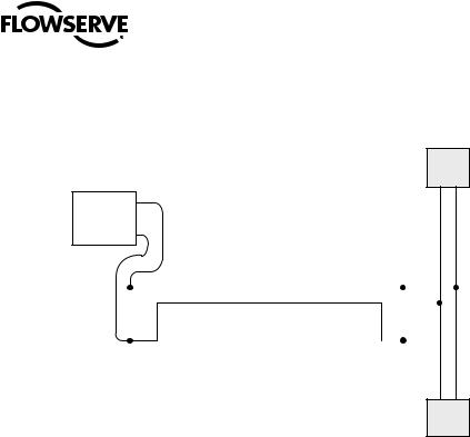
2.2.5.1 Cable Shielding and Grounding for PROFIBUS PA
For best performance, PROFIBUS PA cables must be shielded. When using shielded cable, connect each cable shield to the trunk shield, and connect the overall shield to the PROFIBUS power supply ground.
In Figure 2.9, the grounding point is shown at a connection point of power supply return.
Figure 2.9 – Use of Shielded Cable in PROFIBUS PA
Field
Device
|
|
Shielded Wire Pair |
PROFIBUS |
T |
T |
Interface |
|
|
|
|
|
|
Connect Shield |
Field |
||||
Device |
|||||
to Ground at one |
|
|
|
||
|
|
|
|||
place only |
|
|
|
||
Field
Device
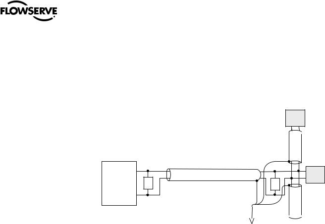
2.2.5.2 PROFIBUS PA Power Supply
The MX/QX PB/PA board requires a nominal 24 VDC (9-32 VDC) on the PA bus to power the MX/QX PB/PA board and make the actuator visible on the network. The required power supply is typically connected to a segment coupler to the bus, usually located at the host end of the cable. Validate the requirements of the segment coupler to determine actual power and voltage.
NOTE: If the actuator does not have three-phase power and the network is active, the MX/QX PB/PA board will report this condition to the host.
22
PB DPV1 / PA Field Unit Installation and Maintenance FCD LMENIM2336-03 – 12/12
Figure 2.10 shows a typical PROFIBUS PA power supply arrangement.
Figure 2.10 – PROFIBUS PA Power Supply
Field
Device
+
Fieldbus
Power - Supply
|
|
|
|
Shielded Wire Pair |
|
|||||
|
|
|
|
Field |
||||||
|
|
|
|
|
|
|
|
|
|
|
PROFIBUS PA |
|
|
|
|
|
|
|
|
|
Device |
|
T |
|
|
T |
|
|
|
|||
|
|
|
|
|
|
|||||
Interface |
|
|
|
|
|
|
|
|
|
|
|
|
|
|
|
|
|
|
|
|
|
|
|
|
|
|
|
|
|
|
|
|
NOTE: Bus power supply may be integrated with the PROFIBUS PA bus interface.
Field
Device
2.3 Other Network Components
In addition to the network cables, the following components may be used in the PROFIBUS network. Each network is designed based on its application and therefore may not require all of these components.
•Bus Terminal Blocks/Junction Box – Provides multiple connections to the bus (network).
•Active Bus Terminal – Provides active termination so that other stations may be powered down for service without affecting the network.
•Connectors – Enable connections to junction boxes, terminators or other connectors. Useful in installations where devices will be periodically disconnected or when a device is only going to be temporarily disconnected. Some PROFIBUS connectors also include termination resistors for line termination.
•Couplers – Provide one or several connection points to a network segment.
•Repeaters – The PROFIBUS Physical Layer (RS-485) dictates that no more than 32 nodes can exist in a shielded twisted-pair (copper) segment. A node is defined as any station, active or passive, that is connected to the network. Media converters (copper to fiber-optic, fiber-optic to copper) and repeaters do not have PROFIBUS addresses and, therefore, are not included in the 126 possible addressable nodes.
RS-485 repeaters may be used to extend the recommended distance of a segment and “reform” the signal to full voltage levels. Repeaters are included in the total number of allowable nodes per segment; therefore, a segment that begins with a repeater and ends with a repeater may have 30 nodes between them. The maximum number of repeaters allowed in a PROFIBUS network is nine. (Refer to Figure 2.11.)
•Terminators – Used at each end of a PROFIBUS segment to prevent signal reflections.
•Power Supplies – Different types of power supplies can be used in a PROFIBUS network:
•Non-intrinsically safe power supply.
•Standard linear or switching power supply used with a power conditioner.
•Intrinsically safe power supply (9-32 VDC; nominal 24 VDC for PA).
23
flowserve.com

PB DPV1 / PA Field Unit Installation and Maintenance FCD LMENIM2336-03 – 12/12
For cable connecting information on these components, refer to the following:
•Installation Guidelines for PROFIBUS – FMS/DP Version 1.0, PROFIBUS International Order No. 2.112.
•Technical Guideline: PROFIBUS PA User & Installation Guideline, Version 2.2, February 2003.
Figure 2.11 – PROFIBUS DP Segments
2.4 Site and Network Cable Preparation
2.4.1 Site Preparation
Prepare the installation site and associated equipment for operation of the MX/QX PB-controlled actuators as follows:
1. |
Prepare a detailed site plan consisting of the following: |
|
|
• |
Actuator locations and tag numbers. |
|
• |
Junction boxes and terminal strip locations and tag numbers. |
|
• |
Terminators and power supplies/conditioners, and repeaters. |
2. |
Provide free access to the MX/QX control panel and terminal block for setup, configuration, and |
|
|
troubleshooting. |
|
3. |
Prepare the cable and label all wires. See Section 2.4.2. |
|
4. |
Install power and control wires in separate conduits. |
|
5. |
Install and verify earth grounds. The cable shields should be tied together. Ground the bus shield |
|
|
at the end of each segment. The MX/QX PB unit should not connect either conductor of the cable |
|
|
to ground at any point in the network. Refer to Sections 2.2.4.1 and 2.2.5.1. |
|
|
NOTE: An effective local earth ground is defined as a low impedance (less than 5 ohms) path to |
|
24 |
either: |
|
|
|
|
|
• |
A ground electrode placed in the close vicinity of the actuator, free of any ground loop currents OR |
PB DPV1 / PA Field Unit Installation and Maintenance FCD LMENIM2336-03 – 12/12
•A safety ground, free of ground loop currents, running from the actuator back to the system ground electrode. If the signal wiring is run on aerial cable where it may be exposed to high-energy electrostatic discharge (such as lightning), a low impedance path to ground which is capable of high current must be provided a short distance from the actuator as described above OR
•A power distribution grid identifying the impact of power isolation to a particular actuator or group of actuators.
2.4.2 Network Cable Preparation
Care must be taken during cable preparation:
•When stripping the insulation, use wire strippers that do not nick the wire.
•Use crimp ferrules to prevent stranded wires from getting loose and shorting to other wires.
•Use vibration-resistant wiring terminals that hold the ferrule securely.
2.4.2.1 Network Cable Connection to the MX/QX PB Unit
The field device is connected to the PROFIBUS network through the MX/QX terminal block.
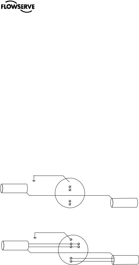
The PROFIBUS DP network cable is connected to the terminal block as shown in Figure 2.12.
NOTE: The MX/QX PB DP device is sensitive to polarity. Cable polarity should be maintained through all connection points.
The PROFIBUS PA network cable is connected to the terminal block as shown in Figure 2.13.
NOTE: The MX/QX PB PA device is equipped with automatic polarity identification. It is not polarity sensitive.
Figure 2.12a – PROFIBUS DP Cable Connections to Terminal Blocks
Earth ground
 3
3
Network data PBDP-A (-) |
|
14 |
|
Network data PBDP-A (+) |
IN |
||
|
|
13 |
|
4 |
|
Network data PBDP-A (-) |
|
OUT |
Network data PBDP-A (+) |
||
5 |
|||
|
|
Figure 2.12b – PROFIBUS DP Cable Connections (Redundancy option with single master) to Terminal Blocks
Earth ground |
|
|
|
|
|
|
|
|
3 |
|
|
Network data PBDP-A (-) |
|
|
14 |
15 |
Note: External jumper connection required between |
Network data PBDP-A (+) |
IN |
|
|
a) Terminals 14 & 15 |
|
|
|
16 |
b) Terminals 13 & 16 |
||
|
|
|
13 |
||
|
|
|
|
|
|
|
|
4 |
|
|
Network data PBDP-A (-) |
|
|
|
OUT |
Network data PBDP-A (+) |
|
|
|
5 |
|
||
|
|
|
|
|
25
flowserve.com
PB DPV1 / PA Field Unit Installation and Maintenance FCD LMENIM2336-03 – 12/12
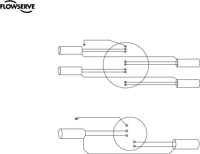
Figure 2.12c – PROFIBUS DP Cable Connections (Redundancy option with dual master) to Terminal Blocks
Earth ground |
|
|
|
|
Network data PBDP |
-A(-) |
|
|
3 |
IN |
|
14 |
||
Network data PBDP |
-A(+) |
|
||
|
13 |
|||
|
|
|
|
|
|
|
|
4 |
OUT |
|
|
|
5 |
|
|
|
|
|
|
Network data PBDP |
-B(-) |
OUT |
|
1 |
Network data PBDP -B(+) |
|
|||
|
2 |
|||
|
|
|
|
|
15 |
IN |
|
16 |
||
|
Network data PBDP -A(-) Network data PBDP -A(+)
Network data PBDP -B(-) Network data PBDP -B(+)
Figure 2.13 – PROFIBUS PA Cable Connections to Terminal Blocks
Earth ground
|
3 |
|
Network data PBPA1(-) |
4 |
|
Network data PBPA1(+) |
||
5 |
||
|
14 |
Network data PBPA1(-) |
|
Network data PBPA1(+) |
||
13 |
||
|
26
PB DPV1 / PA Field Unit Installation and Maintenance FCD LMENIM2336-03 – 12/12
•Shielded twisted-pair cables in compliance to PROFIBUS standards must be used.
•Shields are connected to earth ground. PB/DP connects at the ends of each segment.
PB/PA connects at only a single point in the segment.
•Clean earth-ground connection (less than 5 ohms) provides noise protection and a clear, safe path for surge currents.
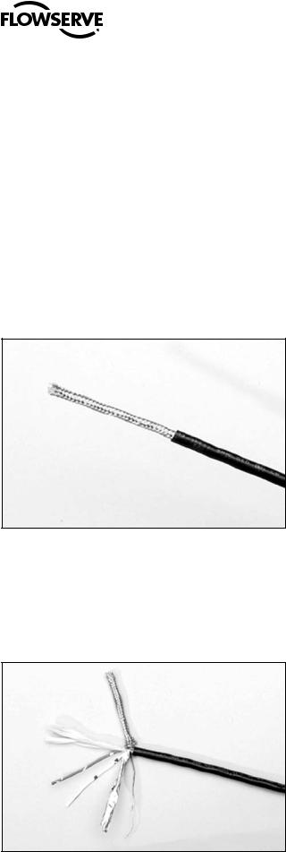
Prepare the network cable for connection to the MX/QX terminals as follows:
aCAUTION: Strip stranded conductors carefully, do not damage the strands. This will weaken the conductor and can cause the conductor to break. This type of damage may not be apparent and failure can occur without warning.
1.Remove two to three inches (5 to 8 cm) of the outer jacket of the cable as shown in Figure 2.14. Do not cut or nick the shield or the insulated conductors.
Figure 2.14 – Removing Outer Plastic Jacket
NOTE: Excess cable should be cut and removed, not coiled or looped, to prevent noise induction into the network.
2.Separate the cable parts. Unbraid the shield and peel back the shield to the same point where the outer jacket was removed as shown in Figure 2.15.
Figure 2.15 – Separating Cable Parts
27
flowserve.com
 Loading...