


|
USER INSTRUCTIONS |
Limitorque MX Electronic Actuator |
Installation |
FCD LMENIM2306-06 - 10/13 |
Operation |
|
Maintenance |
|
|
Experience In Motion

|
|
|
Limitorque MX Electronic Actuator |
FCD LMENIM2306-06 – 10/13 |
|
Contents |
|
||
1 |
Important Notes |
7 |
||
|
2 |
Quick Start |
9 |
|
|
|
2.1 |
Calibrate – Position Limits |
9 |
|
|
|
2.1.1 Entering the Setup Mode |
10 |
|
|
|
2.1.2 Electrical Operation Feature |
10 |
|
|
|
2.1.3 Handwheel Operation Feature |
11 |
|
|
2.2 DDC/Modbus Option |
13 |
|
|
|
2.3 |
Check the Settings |
13 |
|
3 |
Installation and Operation |
14 |
|
|
|
3.1 |
Preparing the Stem Nut |
14 |
|
|
|
3.1.1 Type “B” Bases: Torque-only Applications |
14 |
|
|
|
3.1.2 Type “A” Bases: Thrust-only Applications |
16 |
|
|
|
3.1.3 Type “BL” Drive: Splined Drive Application |
20 |
|
|
3.2 |
Mechanical Installation Onto Valve or Gearbox |
20 |
|
|
|
3.2.1 Mounting (Type “B” Bases): Torque-only |
21 |
|
|
|
3.2.2 Removal (Type “B” Bases): Torque-only |
21 |
|
|
|
3.2.3 Mounting (Type “A” Bases): Thrust-only |
21 |
|
|
|
3.2.4 Removal (Type “A” Bases): Thrust-only |
21 |
|
|
3.3 |
Electrical Connections |
22 |
|
|
|
3.3.1 Removing Terminal Cover |
22 |
|
|
|
3.3.2 Terminal Compartment Documents |
22 |
|
|
|
3.3.3 Sealing Cable/Conduit Entries |
22 |
|
|
|
3.3.4 Recommended Terminal Connections |
22 |
|
|
|
3.3.5 Termination of Cables |
24 |
|
|
|
3.3.6 Cable Connections |
24 |
|
|
|
3.3.7 Network Installations |
24 |
|
|
|
3.3.8 Foundation Fieldbus Installation |
28 |
|
|
|
3.3.9 Network Wiring – Profibus DP/PA Installation |
29 |
|
|
|
3.3.10 Network Wiring – DeviceNet |
29 |
|
|
|
3.3.11 HART Installation |
30 |
|
|
|
3.3.12 Replacing Terminal Cover |
30 |
|
|
|
3.3.13 External Earth/Ground Connections |
30 |
|
|
3.4 |
Terminal Block Shield Installation |
30 |
|
|
3.5 |
Commissioning the Actuator |
30 |
|
|
|
3.5.1 Default Configuration Set |
31 |
|
|
|
3.5.2 View the Existing Settings |
32 |
|
|
|
3.5.3 Entering the Setup Mode |
32 |
|
|
|
3.5.4 Setting Position Limits |
33 |
|
|
3.6 |
Operating the MX Actuator |
36 |
|
|
|
3.6.1 Manual Operation |
36 |
|
|
|
3.6.2 Electrical Operation |
36 |
|
|
|
3.6.3 Local Control |
36 |
|
|
|
3.6.4 Remote Control |
37 |
|
|
|
3.6.5 Local Indication |
37 |
|
4 |
Customizing the Actuator |
38 |
|
|
|
4.1 |
Changing the Existing Settings |
38 |
2 |
|
4.2 |
Password Entry |
41 |
|
4.3 New Password |
41 |
||
|
|
4.4 |
Valve Setup |
42 |

Limitorque MX Electronic Actuator FCD LMENIM2306-06 – 10/13
4.4.1 Close Direction |
42 |
4.4.2 Close Seating |
42 |
4.4.3 Open Seating |
42 |
4.5 Torque Switch Timer |
43 |
4.5.1 Status |
43 |
4.5.2 Torque Timer |
43 |
4.6 Torque Setup |
44 |
4.6.1 Close Torque Valve or Open Torque Valve |
44 |
4.7 Position Setup |
45 |
4.7.1 Set Position Limits for Electrical Operation |
45 |
4.7.2 Set Position Limits for Manual Operation |
45 |
4.8 Modutronic Option |
47 |
4.8.1 Status |
47 |
4.8.2 Proportional Band |
47 |
4.8.3 Fail Position |
47 |
4.8.4 Deadband |
47 |
4.8.5 Polarity (20 mA) |
47 |
4.8.6 Delay After Stop |
48 |
4.8.7 4-20 mA Signal Range |
48 |
4.8.8 Set High Reference |
48 |
4.8.9 Set Low Reference |
48 |
4.8.10 Modutronic LCD Display |
49 |
4.9 DDC/Modbus Option |
49 |
4.9.1 Status |
49 |
4.9.2 Network Address |
50 |
4.9.3 Protocol |
50 |
4.9.4 Analog Scale |
50 |
4.9.5 ESD Action |
50 |
4.9.6 Proportional Band |
51 |
4.9.7 Deadband |
51 |
4.9.8 Offset |
51 |
4.9.9 Move To |
51 |
4.9.10 Comm Loss Delay |
51 |
4.9.11 Comm Loss Action |
51 |
4.10 FF Option |
51 |
4.10.1 Status |
52 |
4.10.2 Terminate Bus |
52 |
4.10.3 Analog Scale |
52 |
4.10.4 ESD Action |
52 |
4.10.5 OPEN/CLOSE Mode |
52 |
4.10.6 Proportional Band |
52 |
4.10.7 Deadband |
52 |
4.10.8 Comm Loss Delay |
53 |
4.10.9 Comm Loss Action |
53 |
4.11 PB Option |
53 |
4.11.1 Status |
54 |
4.11.2 PB DP Operation |
54 |
4.11.3 Comm Loss Delay |
55 |
4.11.4 Comm Loss Action |
55 |
4.12 DN Option |
56 |
4.12.1 Status |
56 |
4.12.2 Baud Rate |
56 |
3
flowserve.com

Limitorque MX Electronic Actuator |
FCD LMENIM2306-06 – 10/13 |
4.12.3 Network Address |
56 |
4.12.4 Analog Scale |
56 |
4.12.5 ESD Action |
56 |
4.12.6 Proportional Band |
57 |
4.12.7 Deadband |
57 |
4.12.8 Comm Loss Delay |
57 |
4.12.9 Comm Loss Action |
57 |
4.13 HART Option |
58 |
4.13.1 Status |
58 |
4.13.2 Multi-drop |
58 |
4.13.3 Input Action |
59 |
4.13.4 Fail Position |
59 |
4.13.5 Polling Address |
59 |
4.13.6 Save Settings |
59 |
4.13.7 Change Prop/Deadband |
59 |
4.13.8 ESD Action |
59 |
4.13.9 Change clock |
60 |
4.14 Status and Alarm Contacts |
60 |
4.14.1 Status and Alarm Contact Default Settings |
60 |
4.14.2 Status Function |
61 |
4.14.3 Contact |
61 |
4.14.4 Valve Position |
62 |
4.15 Two-speed Timer (Optional) |
62 |
4.15.1 Status |
62 |
4.15.2 Start Position |
62 |
4.15.3 Stop Position |
62 |
4.15.4 Pulse Time – ON |
62 |
4.15.5 Pulse Time – OFF |
63 |
4.16 Analog Output |
63 |
4.16.1 APT Polarity Option |
66 |
4.16.2 ATT Polarity Option |
66 |
4.17 Remote Mode |
67 |
4.17.1 Local Control |
67 |
4.17.2 LED Customization |
68 |
4.18 ESD (Emergency Shutdown) Overrides |
68 |
4.18.1 ESD Override |
68 |
4.18.2 Inhibit |
69 |
4.18.3 Local Command |
69 |
4.18.4 Stop |
69 |
4.18.5 Jammed Valve* |
69 |
4.18.6 Lost Phase* |
69 |
4.18.7 Overtorque* |
70 |
4.18.8 Motor Thermostat |
70 |
4.18.9 Oil Over Temperature |
70 |
4.18.10 Two-speed Timer |
70 |
4.18.11 Network ESD |
70 |
4.18.12 Torque Switch Timer |
71 |
4.19 Inputs |
71 |
4.19.1 Input Standard Remote Control |
71 |
4.19.2 Status |
72 |
4

Limitorque MX Electronic Actuator FCD LMENIM2306-06 – 10/13
|
|
4.19.3 Custom Input Mode #1 – Momentary ESD/PSESD (Optional) |
72 |
|
|
4.19.4 Custom Input Mode #2 – Momentary ESD/CSE (Optional) |
74 |
|
|
4.19.5 Custom Input Mode #3 – ESD Time Delay Relay |
74 |
|
|
4.19.6 Custom Input Mode #4 – Multi-position mode (optional) |
74 |
|
|
4.19.7 Limigard Controls |
76 |
|
|
4.19.8 SIL Mode – Standard SIL (Optional) |
76 |
|
|
4.19.9 SIL Mode – Enhanced SIL (Optional) |
77 |
|
4.20 Monitor Relay |
80 |
|
|
4.21 Diagnostic Reset |
81 |
|
|
4.22 TAG Number |
82 |
|
|
4.23 LCD Contrast |
82 |
|
|
4.24 Torque Boost |
82 |
|
|
4.25 Motor Thermostat |
83 |
|
|
4.26 Change Valve Data |
83 |
|
|
4.27 Change Port |
84 |
|
5 |
Troubleshooting |
85 |
|
|
5.1 |
View Diagnostics Routine |
85 |
|
5.2 |
Troubleshooting Problems/Corrective Action |
85 |
|
|
5.2.1 Actuator Fails to Operate |
86 |
|
|
5.2.2 Jammed Valve Detected |
86 |
|
|
5.2.3 Actuator Operates but Does Not Drive Valve |
87 |
|
|
5.2.4 Valve Does Not Seat Correctly |
87 |
|
|
5.2.5 Status Messages |
87 |
|
5.3 |
View Diagnostics |
90 |
|
5.4 |
View Hardware Status |
90 |
|
5.5 |
View Motor Status |
91 |
|
5.6 View Power Supply |
91 |
|
|
5.7 |
View Identification |
92 |
|
5.8 |
View Torque Profile |
92 |
|
5.9 |
View Operation Log |
93 |
|
5.10 View DNET Status? |
94 |
|
6 |
Maintenance |
96 |
|
|
6.1 |
Lubrication |
96 |
|
|
6.1.1 Oil Capacities |
96 |
|
|
6.1.2 Checking Oil Level |
96 |
7 |
Regulatory Information |
97 |
|
|
7.1 |
Special Conditions for Safe Use (denoted by X after the certificate number) |
|
|
|
for Atex and IECEx Applications |
99 |
|
7.2 |
Statement of Compliance With Applicable European Directives |
99 |
5
flowserve.com

Limitorque MX Electronic Actuator FCD LMENIM2306-06 – 10/13
Figures
Figure 1.1 – MX-05 Actuator |
7 |
Figure 2.1 – Electrical operation |
11 |
Figure 2.2 – Handwheel operation |
12 |
Figure 3.1 – B4 base |
14 |
Figure 3.2 – B4E base |
15 |
Figure 3.3 – Exploded view of B4/B4E base (MX-05 shown) |
15 |
Figure 3.4 – B1 base |
16 |
Figure 3.5 – Exploded view of B1 base |
16 |
Figure 3.6 – A1 base |
16 |
Figure 3.7 – Exploded view of A1/A1E base (MX-05/10/20/40 only) |
17 |
Figure 3.8 – Exploded view of thrust base (MX-85 only) |
19 |
Figure 3.9 – Exploded view of thrust base (MX-140/MX-150 only) |
20 |
Figure 3.10 – Power terminal connector size limitations |
23 |
Figure 3.11 – Terminal block rating; power terminals |
23 |
Figure 3.12 – Control terminal connector size limitations |
23 |
Figure 3.13 – View of terminal block |
25 |
Figure 3.14 – Standard wiring diagram |
25 |
Figure 3.15 – Removing outer plastic jacket |
26 |
Figure 3.16 – Separating cable parts |
26 |
Figure 3.17 – Stripping conductors and applying heat shrink tubing |
27 |
Figure 3.18 – Ring tongue connectors |
27 |
Figure 3.19 – Terminal block shield |
30 |
Figure 3.20 – User network connection for loop topology/Typical for all two-wire network protocols |
31 |
Figure 3.21– External earth/ground connection – housing |
31 |
Figure 3.22 – View settings |
33 |
Figure 3.23 – Position setup – electrical operation |
35 |
Figure 3.24 – Declutch lever shows direction of engagement (MX-05 shown) |
36 |
Figure 3.25 – Control panel |
37 |
Figure 4.1 – Entering the setup mode |
39 |
Figure 4.2 – Main menu selections |
40 |
Figure 4.3 – Changing settings |
40 |
Figure 4.4 – Password entry |
41 |
Figure 4.5 – New password |
42 |
Figure 4.6 – Torque Switch Timer |
43 |
Figure 4.7 – MX Nameplate |
44 |
Figure 4.8 – Torque setup |
44 |
Figure 4.9 – Electrical operation |
46 |
Figure 4.10 – Handwheel operation |
46 |
Figure 4.11 – Modutronic option |
48 |
Figure 4.12 – Modutronic signals |
49 |
Figure 4.13 – DDC |
50 |
Figure 4.14 – FF |
53 |
Figure 4.15 – Profibus DP |
54 |
Figure 4.16 – Profibus PA |
55 |
Figure 4.17 – DN option |
57 |
Figure 4.18 – HART |
58 |
Figure 4.19 – Status and alarm contacts (Shown with optional boards needed) |
61 |
6

|
Limitorque MX Electronic Actuator FCD LMENIM2306-06 – 10/13 |
|
Figure 4.20 – Two-speed timers |
63 |
|
Figure 4.21 – Change analog out |
63 |
|
Figure 4.22 – Change analog out voltage – APT |
64 |
|
Figure 4.23 – Change analog out current |
64 |
|
Figure 4.24 – Change analog out voltage – ATT |
65 |
|
Figure 4.25 – Change analog out current – ATT |
65 |
|
Figure 4.26 – Remote mode |
67 |
|
Figure 4.27 – Local control |
67 |
|
Figure 4.28 – ESD overrides |
69 |
|
Figure 4.29 – Custom input modes |
73 |
|
Figure 4.30 – Inputs |
75 |
|
Figure 4.31 – Inputs |
76 |
|
Figure 4.32 – SIL control (Standard) |
77 |
|
Figure 4.33 – SIL control (Enhanced) |
78 |
|
Figure 4.34 – SIL control (Enhanced) |
80 |
|
Figure 4.35 – Diagnostic reset |
81 |
|
Figure 4.36 – TAG number |
82 |
|
Figure 4.37 – LCD contrast |
82 |
|
Figure 4.38 – Torque boost |
83 |
|
Figure 4.39 – Motor thermostat |
83 |
|
Figure 4.40 – Change valve data |
84 |
|
Figure 4.41 – Change port and Bluetooth settings |
84 |
|
Figure 5.1 – Initialize routine |
89 |
|
Figure 5.2 – Diagnostic overview |
90 |
|
Figure 5.3 – View hardware status |
90 |
|
Figure 5.4 – View motor status |
91 |
|
Figure 5.5 – View power supply |
91 |
|
Figure 5.6 – View identification |
92 |
|
Figure 5.7 – View torque profile |
92 |
|
Figure 5.8 – View operation log |
93 |
|
Figure 5.9 – View DNET status |
94 |
|
Figure 7.1 - Typical IEC nameplate |
101 |
|
Figure 7.2 - Typical ATEX nameplate |
102 |
|
Tables |
|
|
Table 3.1 - Hardware and torque for thrust base mounting |
18 |
|
Table 3.2 – Terminal block rating; control terminals |
24 |
|
Table 3.3 – Required ratings for external wires |
24 |
|
Table 3.4 – Loop topology connections |
27 |
|
Table 3.5 – Foundation fieldbus connections |
28 |
|
Table 3.6 – Profibus cable specifications |
29 |
|
Table 3.7 – DeviceNet cable specifications |
29 |
|
Table 3.8 – Default configurations |
32 |
|
Table 3.9 – LED indicators – default settings |
37 |
|
Table 4.1 – Digital input terminals |
79 |
|
Table 7.1 – EMC, EMI standards |
100 |
|
7
flowserve.com
|
|
|
|
Limitorque MX Electronic Actuator |
FCD LMENIM2306-06 – 10/13 |
|
|
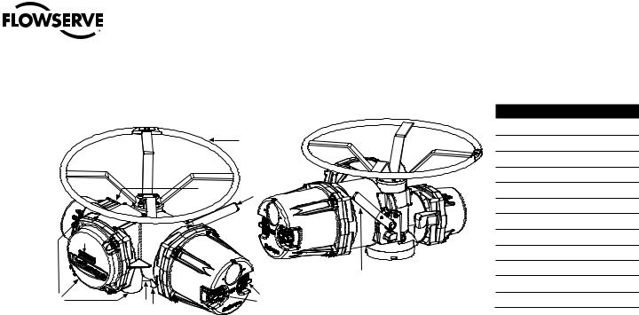
Figure 1.1 – MX-05 Actuator |
|
|
|
|
|
|
|
|
|
|
Piece |
Description |
|
|
|
|
|
1 |
Handwheel |
|
|
|
|
1 |
2 |
Declutch Lever (MX-05) |
|
|
|
|
|
3 |
Oil Fill |
|
|
|
|
|
4 |
Controls Cover |
|
|
3 |
|
2 |
5 |
LCD |
|
|
|
|
|
|
|
|
12 |
|
|
|
6 |
Control Knob |
|
|
|
|
|
|
|
|
11 |
|
|
|
7 |
Ground Lug |
|
10 |
|
|
|
8 |
Thrust/Torque Base |
|
|
4 |
|
|
9 |
Conduit Entry |
|
|
|
5 |
|
10 |
Terminal Compartment |
|
|
|
2 |
11 |
Motor |
|
|
|
|
|
|||
|
|
|
|
|
||
9 |
8 |
7 |
|
6 |
12 |
Nameplate |
|
|
|
|
|
||
1 Important Notes
•Please read this manual in its entirety before attempting to install or operate your MX actuator. A full understanding of the installation and operation options will assist you in installing the actuator in the most effective manner. Limitorque has designed the MX actuator for long life even in the harshest environments. Flexible control and protection options are provided to ensure the actuator meets your requirements.
•All actuator enclosures are sealed by O-rings, and cable entries are supplied with threaded plugs to protect the terminal compartment until the unit is wired. If the actuator cannot be installed immediately, it is recommended that it be stored in a clean, dry place, preferably in an area that is not subject to large fluctuations in temperature.
•Disconnect all incoming power before opening any cover on the actuator. The user/operator must ensure that safe working practices are employed at all times and are in accordance with local or national standards that are enforced at the particular site.
•To install and commission the actuator, only the terminal compartment cover needs to be removed. See Figure 1.1, Item 10. Settings for commissioning the actuator are done externally; therefore, no other covers need to be
8removed. The actuator was assembled in ideal dry conditions and the total sealing of the enclosure protects all electrical components against deterioration.

Limitorque MX Electronic Actuator FCD LMENIM2306-06 – 10/13
NOTE: Removal of any cover, other than the terminal compartment cover, will invalidate the unit warranty. Exposure of actuator components to an environment that results in deterioration of internal components will also invalidate the unit’s warranty.
•During final field installation, ensure that all cable entries are correctly sealed in accordance with National Standards or Regulatory Authorities. All temporary transit plugs must be removed and any unused cable entries closed in an approved manner. See Section 3.3.3, Sealing Cable/Conduit Entries.
9
flowserve.com

Limitorque MX Electronic Actuator FCD LMENIM2306-06 – 10/13
2 Quick Start
Quick Start provides step-by-step instructions for commissioning each MX actuator. This information is also available in Bulletin LMENIM2310, Quick Start-Up Instructions. These instructions are for the following:
•Position limits calibration – can be performed one of two ways:
1.Electrical operation: See Section 2.1.2, Electrical Operation Feature.
2.Handwheel operation: See Section 2.1.3, Handwheel Operation Feature.
•DDC operation: See Section 2.2, DDC Option.
•FF operation: See Section 4.10, FF Option.
•PB operation: See Section 4.11, PB Option.
•DeviceNet operation: See Section 4.12. DN Option.
When these Quick Start instructions are complete, the position limits will be set and the actuator will be ready for normal operation.
NOTE: The actuator has been configured with all customer-specified parameters and no further calibration should be necessary. If full valve data was not provided when ordering, or if changes are needed for parameters, see Sections 3.5 and 6, Commissioning the Actuator and Customizing the Actuator.
2.1 Calibrate – Position Limits
1.Install the MX actuator on the valve.
2.Refer to the nameplate for the correct main power supply voltage. Switch on the main power to the unit.
3.Turn the red knob to the STOP position. The “SET CLOSE POSITION LIMIT” message will be displayed. When the red knob is in “LOCAL” or “REMOTE,” the liquid crystal display (LCD) screen will read “SET POSITION LIMITS.”
4.Calibrate end position limits one of two ways:
•Electrically, using the control panel. See Section 2.1.2, Electrical Operation Feature.
•Manually, using the handwheel. See Section 2.1.3, Handwheel Operation Feature.
Once the position limits have been set, the screen message will indicate the valve position as a percentage of the valve opening.
While setting limit switches, place the red selector knob in the “LOCAL” position to permit the actuator to run open or
closed in push-to-run mode (inching) only.
10
a CAUTION: Extreme care must be taken as the valve approaches its end position.
The unit will not function with the red selector knob in the “REMOTE” position until both limit switches are set.
Limitorque MX Electronic Actuator FCD LMENIM2306-06 – 10/13
The existing configuration of the actuator/valve parameters may be viewed by entering the “SETUP” mode.
2.1.1 Entering the Setup Mode
1. Place the red selector knob in the “STOP” position.
2. Within 10 seconds, place the black control knob in the “YES” position, then the “NO” position, then again in the “YES” position (in quick succession—approximately one-two seconds).
3. The message “SETUP?” will appear in the LCD display for 10 seconds. If no setup action is taken within 10 seconds, the unit will reset.
4. Use the black control knob to answer “YES” or “NO” to the questions appearing in the display.
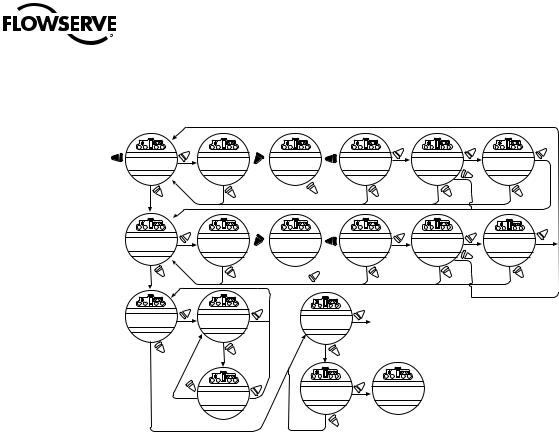
2.1.2 Electrical Operation Feature
This feature allows for quick and simple calibration. To set the position limits electrically, enter the “CHANGE SETTINGS” mode via the “SETUP” mode.
1.Enter the “SETUP” mode as detailed in Section 2.1.1, Entering the Setup Mode.
2.When screen prompt reads “CHANGE SETTINGS,” select “YES.”
3.The screen will display the “CHANGE SETTINGS” mode menu items. Select “NO” until screen displays “CHANGE POSITION SETUP.” User may select to set close limit first or open limit first.
4.Select “YES.” “CLOSE” or “OPEN VALVE - OK?” is displayed.
5.Place the red selector knob in the “LOCAL” position. Move the black knob in the intended direction. The LCD screens are shown in Figure 2.1.
6.When valve has reached desired position, return the red selector switch to “STOP” and complete calibration.
The position settings are now complete. The actuator will now function as ordered, and may be run electrically to inspect for correct operation.
aCAUTION: On some valves, position limits could be set adjacent to each other, so be careful that the Close and Open limits are set sufficiently apart to permit operation. If the limits are set adjacent of each other, an error message will be displayed: “KEEP OPEN(CLOSE) LIMIT?”
NO FURTHER MOVEMENT IS PERMITTED UNTIL THE ERROR IS CORRECTED.
Should the User elect to proceed with the setting, an error will be displayed on the screen after re-booting stating “IDENTICAL LIMITS”. THE ACTUATOR WILL NOT MOVE UNTIL THE ERROR IS CORRECTED.
11
flowserve.com
Limitorque MX Electronic Actuator FCD LMENIM2306-06 – 10/13
Figure 2.1 – Electrical operation
STOP |
YES |
Switch to |
YES |
YES2 |
YES |
STOP |
|
|
SET CLOSE |
|
CLOSE VALVE |
|
CLOSE VALVE |
CLOSE VALVE |
SAVE CLOSE |
|
IDENTICALLIMITS |
|
POSITION LIMIT? |
|
OK ? |
LOCAL |
RETURN TO STOP |
OK ? |
LIMIT OK? |
|
KEEPCLOSELIMIT? |
|
|
|
|
|
|
|
|
|
YES1 |
|
|
|
|
“NO ” operates |
NO |
|
|
|
|
|
NO |
|
NO |
close direction |
NO |
NO |
|
NO |
||
|
|
|
|||||||
|
YES |
|
Switch to |
|
STOP |
YES |
|
YES2 |
YES |
|
|
|
|
|
|
|
|
|
|
SET OPEN |
|
OPEN VALVE |
|
OPEN VALVE |
OPEN VALVE |
SAVE OPEN |
|
IDENTICALLIMITS |
|
POSITION LIMIT? |
|
OK ? |
LOCAL |
RETURN TO STOP |
OK ? |
LIMIT OK? |
|
KEEPOPENLIMIT? |
|
|
|
|
|
|
|
|
|
YES1 |
|
|
|
|
“YES” operates |
YES |
|
|
|
|
|
|
|
|
|
|
|
|
|
||
NO |
|
NO |
open direction |
|
NO |
NO |
|
NO |
|
|
YES |
|
YES |
|
|
YES |
|
|
|
SET POSITION |
|
POSITION |
|
|
SETUP? |
Enter “SETUP ” mode |
NOTE 1: If open and close limits |
||
PRECISION? |
|
XXX% OPEN? |
|
|
|
|
are not identical |
||
|
|
|
|
|
|
|
|
|
|
|
|
|
|
|
|
|
|
NOTE 2: If open and close limits |
|
NO |
|
|
|
|
|
|
|
|
are identical |
|
NO |
|
|
NO |
|
|
|
|
|
|
|
|
YES |
|
|
YES |
|
|
|
|
|
|
|
|
100% OPEN |
|
|
|
|
|
NO |
POSITION |
|
|
EXIT |
|
|
|
|
|
|
|
|
SETUP? |
STATUS OK? |
|
|
|
|
|
|
XXX.X% OPEN? |
|
|
|
|
|
|
|
NO
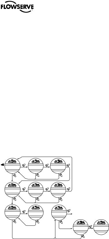
2.1.3 Handwheel Operation Feature
To set the position limits manually, enter the “CHANGE SETTINGS” mode via the “SETUP” mode.
1.Enter the “SETUP” mode as detailed in Section 2.1.1, Entering the Setup Mode.
2.When LCD reads “CHANGE SETTINGS?”, select “YES.”
3.The LCD will display the “CHANGE SETTINGS” mode menu items. Select “NO” until screen displays “CHANGE POSITION SETUP?”
4.Select “YES.” See Figure 2.2. Manually set position limits:
a.Close position limit
1.“SET CLOSE POSITION LIMIT?” is displayed.
2.Select “YES.” “CLOSE VALVE - OK?” is displayed.
3.Depress the declutch lever, and at the same time slowly rotate the handwheel until the clutch is fully engaged. Release the lever; the clutch will be retained in the handwheel mode by spring-loaded latches.
4.Ensure the valve is fully closed, then move the valve in the open direction for one handwheel turn to allow for coasting of the motor.
5.When the valve is in the desired position, select “YES” again. The LCD will read “SAVE CLOSE LIMIT OK?”
6.Select “YES” if the valve’s close limit position is correct. The close position limit is set.
b.Open position limit
12
1. “SET OPEN POSITION LIMIT?” is displayed.
2. Select “YES.” “OPEN VALVE - OK?” is displayed.
Limitorque MX Electronic Actuator FCD LMENIM2306-06 – 10/13
3.Depress the declutch lever, and at the same time slowly rotate the handwheel until the clutch is fully engaged. Release the lever; the clutch will be retained in the handwheel mode by spring-loaded latches.
4.Ensure the valve is fully open, then move the valve in the close direction for one handwheel turn to allow for coasting of the motor.
5.When the valve is in the desired position, select “YES” again. The LCD will read “SAVE OPEN LIMIT OK?”
6.Select “YES” if the valve’s open position limit is correct. The open position limit is set.
7.Move the valve in the close direction. The open lamp should extinguish within one turn of the handwheel.
8.Move the valve back in the open direction and check that the open lamp illuminates just before the full open position is reached (approximately 1/2 to 1 turn).
9.If the calibration requires adjustment, select “NO” at the “SET CLOSE POSITION LIMIT?” prompt and repeat the “SET OPEN POSITION LIMIT?” routine.
10.Select “NO” to exit “POSITION SETUP?” or “YES” to return to “SET CLOSE POSITION LIMIT?”
aCAUTION: On some valves, position limits could be set adjacent to each other, so be careful that the Close and Open limits are set sufficiently apart to permit operation. If the limits are set adjacent to each other, an error message will be displayed: “KEEP OPEN(CLOSE) LIMIT?”
NO FURTHER MOVEMENT IS PERMITTED UNTIL THE ERROR IS CORRECTED.
Should the User elect to proceed with the setting, an error will be displayed on the screen after re-booting stating “IDENTICAL LIMITS”. THE ACTUATOR WILL NOT MOVE UNTIL THE ERROR IS CORRECTED.
Figure 2.2 – Handwheel operation
STOP |
YES |
YES |
YES |
|
SET CLOSE |
CLOSE VALVE |
SAVE CLOS E |
|
|
||
POSITION LIMIT? |
OK ? |
|
LIMIT OK? |
|
|
|
|
|
Declutch actuator; |
|
|
|
|
NO |
NO |
Rotate handwheel to |
NO |
|
|
|
“CLOSE” position limit |
|
|
||||
|
|
|
|
|||
YES |
|
YES |
|
|
YES |
|
SET OPEN |
OPEN VALVE |
|
SAVE OPEN |
|
|
|
POSITION LIMIT? |
OK ? |
|
LIMIT OK? |
|
|
|
NO |
|
Rotate handwheel to |
|
|
|
|
NO “OPEN” position limit |
NO |
|
|
|||
YES |
|
|
|
|
YES |
|
|
|
|
|
|
|
|
SET POSITION |
POSITION |
|
|
SETUP? |
Enter “SETUP” mode |
|
PRECISION? |
XXX% OPEN |
|
|
|
||
NO |
NO |
|
|
NO |
|
YES |
|
|
|
|
|
EXIT |
100% |
|
|
|
|
|
SETUP? |
STATUS OK |
NO
13
flowserve.com

Limitorque MX Electronic Actuator FCD LMENIM2306-06 – 10/13
2.2 DDC/Modbus Option
The following instructions assume that all DDC option parameters are set with the exception of the address.
1.After setting position limits, remain in the “SETUP” mode. If not in the “SETUP” mode, enter the “SETUP” mode as detailed in Section 2.1.1, Entering the Setup Mode.
2.When LCD reads “CHANGE SETTINGS?”, select “YES.”
3.The LCD will display the “CHANGE SETTINGS” mode menu items. Select “NO” until screen displays “CHANGE DDC?” Select “YES.” LCD will display DDC menu items.
4.Select “YES” for each menu item until “DDC ADDRESS OK?” appears. Select “NO.”
5.Enter an address from one to 250 by toggling “NO” until the correct address is displayed. User may select to hold the knob in the “NO” direction and the number will automatically increment by one until the preferred address is reached.
aCAUTION: The network address must be entered in accordance with the user address assignment sheet. This assignment sheet should correspond to the contract specifications. The same address must not be used anywhere else in the same network.
The DDC address does not have to be set to exit the setup.
2.3 Check the Settings
1.Operate the valve to the fully “CLOSE” position. Verify that the “CLOSE” (default GREEN) LED illuminates just as the travel limit is reached, and the valve position is displayed as “0% OPEN.”
2.Operate the valve to the fully “OPEN” position. Verify that the “OPEN” (default RED) LED illuminates just as the travel limit is reached, and the valve position is displayed as “100% OPEN.”
14

Limitorque MX Electronic Actuator FCD LMENIM2306-06 – 10/13
3 Installation and Operation
3.1 Preparing the Stem Nut
The MX has two (2) basic base designs:
•Torque-only base, designated by a “B” prefix
•Thrust-only base, designated by an “A” prefix
3.1.1 Type “B” Bases: Torque-only Applications
Standard B4/B4E Base
The standard MX actuator base is the B4 torque-only. It includes a mounting plate and steel torque nut, which may be machined to fit a valve or gearbox. A B4E torque nut can be provided and may be installed to allow for extended stem acceptance.
NOTE: Some MX actuators are supplied with single piece drive sleeves that have been bored and keyed. These are typically mounted directly to gearboxes. The MX actuator maybe mounted in any position as long as the handwheel is accessible.
Figure 3.1 – B4 base
15
flowserve.com
Limitorque MX Electronic Actuator FCD LMENIM2306-06 – 10/13
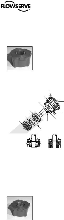
Figure 3.2 – B4E base
Figure 3.3 – Exploded view of B4/B4E base (MX-05 shown)
Baseplate |
Drive sleeve |
MX base
Torque nut
Retaining ring
Disassembly
1.Remove the retaining ring (B4 base) or spiral-wound ring (B4E base) that retains the torque nut in the drive sleeve.
2.Remove the torque nut. If the torque nut is difficult to remove, insert a suitable device into the drive sleeve through bore and gently tap it loose from the handwheel end.
3.Machine the torque nut to suit the valve stem or gearbox input shaft (see LMENSS2326, MX Performance and Dimensions for maximum stem capacity). Ensure sufficient clearance for a smooth, sliding fit.
Reassembly
1.Clean the torque nut thoroughly and lightly grease.
2.Replace the torque nut in the drive sleeve. Ensure the torque nut meshes with the drive lugs.
3.Refit the retaining ring (B4 base) or spiral-wound ring (B4E base).
Optional B1 Base (not available for MX-85, MX-140 and MX-150)
16An optional torque base assembly may be added to allow for a greater stem acceptance. This base is supplied with a fixed bore and key as defined by ISO 5210.
Limitorque MX Electronic Actuator FCD LMENIM2306-06 – 10/13
Disassembly
No disassembly is required since the torque nut has been machined to an international standard. Clean the bore and lightly grease.
Figure 3.4 – B1 base
NOTE: Fill base with a Lithium based EP0 grease.
Figure 3.5 – Exploded view of B1 base
Pipe plug
Socket head cap screw (M8 x 20)
Torque nut (B1) |
Housing, |
|
torque/thrust |
Bearing
Pipe plug
Retainer, bearing
Pilot, torque/thrust
Thrust nut assembly
Washer (M4)
Socket head
cap screw (M4 x 8)
Socket head set screw
MX-05 B1 |
MX-40 B1 |
3.1.2 Type “A” Bases: Thrust-only Applications
Standard A1/A1E Base
The standard MX actuator thrust base is the A1, and may be bolted directly to the actuator. The thrust base contains a bronze alloy thrust nut that may be machined to suit the valve stem.
An A1E (extended) thrust nut can be provided and may be installed to reach shorter stems.
Figure 3.6 – A1 base
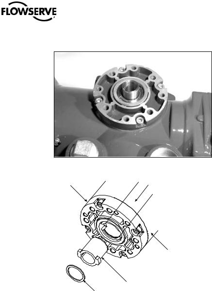
Disassembly – Units MX-05/10/20/40
Refer to Figure 3.7.
Disassembly of the main housing from the base may be recommended to allow the base to remain on the valve if the |
17 |
actuator must be removed for service. |
|
flowserve.com

Limitorque MX Electronic Actuator FCD LMENIM2306-06 – 10/13
Pilot removal
MX-10/20: Remove the screw and washer holding the valve pilot to the thrust base and remove pilot.
MX-40: Turn counterclockwise (CCW) and remove.
Thrust bearing and nut removal
1.Remove the first set of thrust washers and bearing.
2.Remove stem nut.
NOTE: The thrust washers, bearing, and thrust nut may be removed at the same time. The second set of thrust washers and bearing does not have to be removed.
3.Machine the thrust nut to suit the valve stem. Ensure sufficient clearance to avoid unnecessary wear and heating during operation.
Reassembly – Units MX-05/10/20/40
Refer to Figure 3.7.
1.Clean the thrust nut, washers, and bearing(s) thoroughly.
2.Slide second set of thrust washers and bearing in place if removed.
NOTE: Order of assembling thrust washers and bearing must be as follows: washer, thrust bearing, washer.
Pilot installation
MX-05/10/20: Slide pilot into thrust base assembly and secure with washer and screw. Tighten fully.
MX-40: Place pilot into thrust base and turn clockwise (CW) until pilot is tight.
NOTE: Fill base with Nebula EP 0, Conoco Conolith EP 00, Mobil SHC 632, Dynalife-L-EP0, Triton ELL, or Lithium based EP0 grease.
Disassembly – Units MX-85
Refer to Figure 3.8.
Disassembly of the main housing from the base may be recommended to allow the base to remain on the valve if the actuator must be removed for service.
Thrust base mounting plate removal
Remove the six socket head cap screws holding the valve mounting plate to the thrust base housing and remove mounting plate.
Figure 3.7 – Exploded view of A1/A1E base (MX-05/10/20/40 only)
Housing
Quad ring
Socket head cap |
|
Thrust washer |
|
Thrust Nut |
|
Thrust washer |
Pipe plug |
O-ring
Thrust pilot
Needle bearing
18
Quad ring
Washer
Socket head cap screw Thrust base standard nut
Thrust base extended nut

Limitorque MX Electronic Actuator FCD LMENIM2306-06 – 10/13
Thrust bearing and nut removal
1.Remove the first set of thrust washers and bearing.
2.Remove stem nut.
NOTE: The thrust washers, bearing, and stem nut may be removed at the same time. The second set of thrust washers and bearing does not have to be removed.
3.Machine the stem nut to suit the valve stem. Ensure sufficient clearance to avoid unnecessary wear and heating during operation.
Reassembly – Units MX-85
Refer to Figure 3.8.
1.Clean the stem nut, washers, and bearing(s) thoroughly.
2.Slide second set of thrust washers and bearing in place if removed.
3.Install stem nut. Lubricate thoroughly.
4.Install first set of thrust washers and bearing.
NOTE: Order of assembling thrust washers and bearing must be as follows: washer, thrust bearing, washer.
NOTE: Fill base with Nebula EP 0, Conoco Conolith EP 00, Dynalife-L-EP0, Mobil SHC 632, Triton ELL, or Lithium based EP0 grease.
Thrust baseplate installation
Mount baseplate to thrust base housing and install the six socket head cap screws to the proper torque per Table 3.1.
Table 3.1– Hardware and torque for thrust base mounting
Screw Size |
|
Torque |
|
ft-lb |
|
N m |
|
|
|
||
M8 or 5⁄16 in. (8 mm) |
|
|
16-19 |
12-14 |
|
||
M10 or 3⁄8 in. (9 mm) |
25-30 |
|
33-40 |
M12 or 1/2 in. (13 mm) |
40-50 |
|
53-67 |
|
|
|
|
M16 or 5⁄8 in. (16 mm) |
90-100 |
|
122-135 |
M20 or 3/4 in. (19 mm) |
180-200 |
|
244-271 |
|
|
|
|
NOTE: Screw mounting torque for mounting thrust base to main housing or thrust baseplate to thrust base housing.
19
flowserve.com
Limitorque MX Electronic Actuator FCD LMENIM2306-06 – 10/13
Figure 3.8 – Exploded view of thrust base (MX-85 only)
Pipe plug Housing
|
Socket head |
|
cap screws |
|
Thrust bearing |
Thrust nut |
|
Baseplate Thrust bearing |
|
Socket head |
|
cap screws |
Thrust |
|
Quad ring washer |
Quad ring
Thrust
O-ring washer
A
A
Section A-A |
Section A-A |
View shown |
View shown |
with standard nut |
with extended nut |
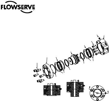
Disassembly – Units MX-140/MX-150
Refer to Figure 3.9.
Disassembly of the main housing from the base may be recommended to allow the base to remain on the valve if the actuator must be removed for service.
Pilot removal
Remove the two screws and washers holding the valve pilot to the thrust base and remove pilot.
Thrust bearing and nut removal
1.Remove the first set of thrust washers and bearing.
2.Remove stem nut.
NOTE: The thrust washers, bearing, and stem nut may be removed at the same time. The second set of thrust washers and bearing does not have to be removed.
3.Machine the stem nut to suit the valve stem. Ensure sufficient clearance to avoid unnecessary wear and heating during operation.
Reassembly – Units MX-140
Refer to Figure 3.9.
1.Clean the stem nut, washers, and bearing(s) thoroughly.
2.Remove pipe plug.
3.Slide second set of thrust washers and bearing in place if removed.
4.Install stem nut. Lubricate thoroughly.
5.Install first set of thrust washers and bearing.
6.Install pipe plug.
NOTE: Order of assembling thrust washers and bearing must be as follows: washer, thrust bearing, washer.
20NOTE: Fill base with Nebula EP 0, Conoco Conolith EP 00, Dynalife-L-EP0, Mobil SHC 632, Triton ELL, or Lithium based EP0 grease.
Limitorque MX Electronic Actuator FCD LMENIM2306-06 – 10/13
Pilot installation
Slide pilot into thrust base assembly and secure with the two washers and screws. Tighten fully.
3.1.3 Type “BL” Drive: Splined Drive Application
Steel alloy splined nuts are provided to a standard involute spline category for rising and rotating stem valves per customer requirements. Disassembly and reassembly is the same as the B4 base and the torque nut. See Section 3.1.1, Type “B” Bases: Torque-only Applications.
Figure 3.9 – Exploded view of thrust base (MX-140/MX-150 only)
|
|
Housing |
Pipe plug |
|
|
|
|
||
|
|
Thrust |
|
|
|
|
bearing |
|
|
|
|
Thrust nut |
|
|
|
Thrust |
|
Socket |
|
|
|
head cap |
||
|
bearing |
Thrust |
screws |
|
|
O-ring |
|
||
Thrust |
washers |
Pipe plug |
||
|
Quad ring |
|
||
pilot |
|
|
||
|
|
|
||
|
|
Quad ring |
|
|
|
|
Thrust |
|
|
|
|
washers |
A |
|
Socket head Washers |
B |
|||
|
||||
cap screws |
|
|
|
|
|
Section A-A |
Section B-B |
B |
|
View shown with |
View shown with |
|
||
|
standard nut |
extended nut |
A |
|
3.2 Mechanical Installation Onto Valve or Gearbox
NOTE: Refer to MX Maintenance and Spare Parts bulletin (LMENIM2314) for more detailed instructions.
Before installing the actuator onto a valve or gearbox, check the following to ease installation:
•Verify that mounting flange is suited dimensionally to mate with the actuator base. Ensure that it is perpendicular to the valve stem or gearbox input shaft.
•Ensure the stem nut mates with the valve stem or input shaft. For screwed nuts, it is advisable to run the stem nut down the entire length of the stem to check for tightness. Keyed or splined shafts should exhibit a smooth, sliding fit with the key installed.
•Ensure there is adequate engagement of the stem nut with the valve stem or input shaft when mounted. Generally, the minimum length of engagement is 1.5 times the diameter of the stem.
•Verify that mounting studs or bolts are the correct length to suit the thickness of the mounting plate.
•Verify hardware specifications for English style:
•Socket head cap screw per ASTM A 574 and ANSI 18.3.
•Hex head cap screw per SAE J429 Grade 5.
•Verify hardware specifications for metric style: hex and socket head cap screws per Property Class 12.9.
•Clean and lubricate the valve stem or input shaft.
•Ensure adequate lifting facilities and slings are available at the installation site.
NOTE: Do not use the handwheel to lift the actuator. |
21 |
|
flowserve.com

Limitorque MX Electronic Actuator FCD LMENIM2306-06 – 10/13
3.2.1 Mounting (Type “B” Bases): Torque-only
Refer to Figures 3.1 - 3.5.
1.Ensure torque nut is secured inside actuator drive sleeve with retaining ring.
2.Lower actuator onto the valve or gearbox stem. Align the stem nut key and keyway with valve or gearbox stem key seat.
3.Verify that the actuator and valve mounting adapter flanges mate correctly.
4.Secure the actuator to the valve mounting adapter with mounting bolts.
3.2.2 Removal (Type “B” Bases): Torque-only
Refer to Figures 3.1 – 3.5.
1.Remove the bolts that secure the actuator to the valve mounting adapter. If type B1 base is used in addition to the standard type B4 baseplate, you may leave the B1 base attached to the actuator and remove as a unit.
2.Lift the actuator from the actuator mounting adapter.
3.2.3 Mounting (Type “A” Bases): Thrust-only
Refer to Figures 3.6 – 3.9.
1.The following are two options for mounting the type A base actuator:
a.If the type A thrust base was removed from the valve mounting adapter, replace the thrust base onto the valve mounting adapter. Ensure the thrust base stem nut has the lugs positioned upward to engage with the drive sleeve slots when the actuator is reinstalled. Rotate the bronze nut while holding the base steady.
or
b. If the thrust base is installed on the valve mounting adapter, proceed to step two.
2.Lower the actuator along the threaded valve stem and onto the valve mounting plate. Ensure the thrust base stem nut lugs properly engage and align with the drive sleeve slots.
3.Install the bolts to secure the actuator to the thrust base assembly.
3.2.4 Removal (Type “A” Bases): Thrust-only
1.Remove the bolts that secure the actuator to the thrust base assembly.
2.Remove the type A thrust base by removing the bolts that secure the actuator to the valve mounting adapter. or
Leave the type A thrust base mounted to the valve mounting adapter until ready to remount the actuator. The thrust base will maintain valve position provided that the valve stem threads are locking.
3.Lift the complete actuator from the thrust base.
22

Limitorque MX Electronic Actuator FCD LMENIM2306-06 – 10/13
3.3 Electrical Connections
Verify that the supply voltage details on the nameplate are correct for this installation. Setup is non-intrusive; therefore, remove only the terminal cover to make electrical connections and to commission the actuator.
cWARNING: The removal of any other covers without Limitorque’s approval will void the warranty. Limitorque will not accept responsibility for any damage or deterioration that may occur as a result of cover removal.
3.3.1 Removing Terminal Cover
Remove the terminal cover as follows:
1.Remove the four cover screws using a 6 mm hexagonal wrench.
2.Remove the cover. XP units have long-spigoted covers and two tapped holes 180° apart. If the XP cover is difficult to remove, fit two of the cover screws into the tapped holes in the cover flange and jack out the cover. Take care to turn the screws by equal increments. Do not lever the cover off with a screwdriver, or similar object, since this may damage the flamepath on an explosionproof unit or the O-ring seal and seating face.
3.3.2 Terminal Compartment Documents
The OEM and user installation kits, wiring diagram, and test report are contained in the terminal compartment or with the actuator. Do not place them in the terminal compartment when the electrical connections have been completed.
NOTE: This instruction does not apply to valve manufacturers or similar installers of the actuator onto a valve prior to shipping to site. It is important that these items are available at the final destination site.
3.3.3 Sealing Cable/Conduit Entries
The sealing of cables and conduit entries should be done in accordance with National Standards or the Regulatory Authorities that have certified the actuators. This is particularly true for units that are certified for use in hazardous areas where the method of sealing must be to an approved standard and cable glands, reducers, plugs, and adapters must be approved and separately certified. All conduit entries should be sealed against the climatic conditions prevailing on-site, especially if temporary submersion is possible. All unused conduit entries should be sealed with threaded metal plugs. Plastic plugs are installed by Limitorque for shipping only and must not be used as permanent seals.
3.3.4 Recommended Terminal Connections
Power Terminals
Ring tongue connectors used on the power terminals should comply with the dimensions shown in Figure 3.10. For Additional information, consult terminal manufacturer.
Figure 3.11 details the allowable voltage and current parameters for the terminal block power terminals. Preload the M5 screws to 1.6-3.2 N m (1.2-2.33 ft-lb).
Control Terminals
Ring tongue connectors used on the control terminals should comply with the dimensions shown in Figure 3.12. For additional information, consult terminal manufacturer. Preload the M3 screws to 0.33-0.66 N m (0.25-0.50 ft-lb).
NOTE: Alternative manufacturers may be substituted only if dimensions are in accordance with Figure 3.12.
NOTE: The use of spade terminals is not recommended for secure electrical connections.
23
flowserve.com
Limitorque MX Electronic Actuator FCD LMENIM2306-06 – 10/13
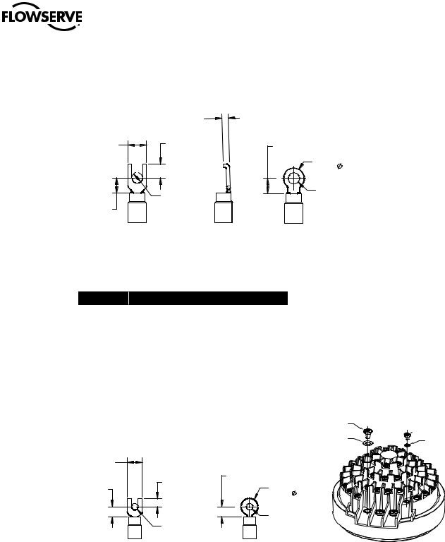
Figure 3.10 – Power terminal connector size limitations
MAX. THICKNESS = 1.6 mm
|
NOT TO |
|
|
|
EXCEED 3.5 |
|
|
NOT TO |
NOT TO |
NOT TO |
|
EXCEED 9.8 |
EXCEED 6.5 |
EXCEED 15 |
|
|
|
NOT TO |
|
|
|
EXCEED 9.6 |
|
|
TO BE SIZED |
TO BE SIZED |
|
|
FOR M5 SCREW |
||
|
FOR M5 SCREW |
||
NOT TO |
|
||
|
|
||
EXCEED 15 |
|
|
|
SPADE AND SNAP |
FLANGED |
RING TERMINAL |
|
TERMINALS |
SPADE TERMINAL |
||
|
Figure 3.11 – Terminal block rating; power terminals
Description |
L1 |
L2 |
L3 |
|
|
30 AMP |
20 AMP |
15 AMP |
|
|
||||
|
|
|
|
|
STD Rating |
8 Awg/10 mm2 |
10 Awg/6 mm2 |
14 Awg/2.5 mm2 |
|
|
600 VAC |
RMS |
150 VDC |
|
|
|
|
|
|
Increased |
27 AMP |
18 AMP |
13.5 AMP |
|
|
|
|
||
8 Awg/10 mm2 |
10 Awg/6 mm2 |
14 Awg/2.5 mm2 |
||
Safety Rating |
||||
500 VAC |
RMS |
150 VDC |
||
|
||||
|
|
|
|
Note: Ratings will be the same for L1, L2, or L3, e.g., if 10 Awg is selected, then L1, L2 and L3 will have the same limitations.
Figure 3.12 – Control terminal connector size limitations
NOT TO |
MAX. THICKNESS = 1.0 mm |
|
|
|
|
EXCEED 7.6 |
|
NOT TO |
|
NOT TO |
|
NOT TO |
EXCEED 5 |
|
EXCEED 4.0 |
NOT TO |
|
EXCEED 5 |
|
EXCEED 8.2 |
|
|
TO BE SIZED |
|
TO BE SIZED |
FOR M3 SCREW |
|
|
|
|
FOR M3 SCREW |
|
SPADE AND SNAP |
|
RING TERMINAL |
TERMINAL |
|
|
3X M5 SCREW
 54X M3 SCREW
3X M5 SPRING
WASHER 54X M3 SPRING WASHER
FIGURE 3.13
THE USE OF THE SPRING WASHERS ARE REQUIRED
ON INCREASED SAFETY APPLICATIONS.
NOTE: All dimensions are in mm.
NOTE: Limitorque recommends the use of the following connector for optimum results: Thomas and Betts #RZ22-6.
24NOTE: Alternative manufacturers may be substituted only if the dimensions are in accordance with Figure 3.12. Table 3.2 lists the maximum allowable voltage and current parameters for the terminal block control terminals.

Limitorque MX Electronic Actuator FCD LMENIM2306-06 – 10/13
Table 3.2 – Terminal block rating; control terminals
|
Low Voltage Row |
STD Rating |
Increased Safety Rating |
|
1 points 1-16, 50 Volt |
0.5 AMP AC RMS |
0.45 AMP AC RMS |
|
|||
|
|
|
|
|
2 points 17-35, 125 Volt |
0.5 AMP AC RMS |
0.45 AMP AC RMS |
|
|
|
|
|
3 and 4 points 36-54, 250 Volt |
5 AMP AC RMS |
4.5 AMP AC RMS |
|
|
|
|
3.3.5 Termination of Cables
All terminations should be made with insulated ring terminals using the appropriate crimping tool. See Figures 3.10 and 3.11 for power terminal connection recommendations. See Figure 3.12 and Table 3.2 and 3.3 for control terminal connection recommendations.
3.3.6 Cable Connections
See Figure 3.14 for connection information.
1.Connect the main power supply cables, including the earth/ground wire using the M5 screws provided.
2.Attach the earth/ground wire to the separate screw on the inside of the terminal compartment.
3.Use the M3 screws installed in the terminal block to connect the control cables in accordance with the wiring diagram and the project specification.
4.Ensure that all connections are tight, including any spare termination screws that have not been used.
NOTE: A “Customer Connection(s) Diagram” sticker is attached to the interior of the terminal compartment cover. This may be removed and user termination numbers inscribed adjacent to Limitorque’s terminal block numbers for field connection reference. The diagram may also be used to assist in locating the terminal block positions. Service and factory contacts are contained on the sticker.
Certification is based on the use of appropriately rated wire for the application. Installation shall be in accordance with the current issue of the applicable national and or local electric code or regulations.
Table 3.3 – Required ratings for external wires
Up to |
|
Use wire rated at least |
40°C Ambient |
|
75°C |
|
||
|
|
|
55°C Ambient |
|
90°C |
|
|
|
60°C and 65°C Ambient1 |
|
105°C |
Note 1: Refer to unit nameplate.
3.3.7 Network Installations
The Limitorque MX offers a number of network options: DDC-Modbus, Foundation Fieldbus H1, Profibus DP_V1, Profibus PA, and DeviceNet.
Ensure that the network cable type is Belden 3074F, Belden 3105, Belden 9841 or another cable that is within 5% of the following specifications.
• |
Nominal impedance: 120 ohms @ 1 MHz |
|
• |
Line to shield capacitance: 23.0 pF/ft (75.5 pF/m) |
|
• |
Line to line capacitance: 12.8 pF/ft (42.0 pF/m) |
25 |
Using other cables may result in decrease of internodal distance and/or an increase in communication error.
flowserve.com

Limitorque MX Electronic Actuator FCD LMENIM2306-06 – 10/13
Particular care should be taken when terminating twisted-pair shielded cables in a control network. Avoid nicks, cuts, or abrasions in the insulation of data communication cables, since this may result in inadvertent ground connection. Also, excess cable should be cut, not coiled or looped, to prevent noise induction into the network.
Limitorque strongly recommends remote communication wiring be routed separately from mains line power wiring. Specifically, instrumentation wiring, including communication, analog and discrete signal wiring, should be routed in conduit that is separated from power lines. If the recommendation is not followed, the intergrity of instrumentation signals may be comprimised. If the signal is comprimised, the MX will enter a“safe-state” whereby all motion is prohibited until communication is sucessfully re-established.
Figure 3.13 – View of terminal block
Figure 3.14 – Standard wiring diagram
NOTE: Most current wiring diagram is shipped within the terminal compartment of the MX.
|
|
|
PE |
|
|
|
|
L1 |
Three-phase supply |
|
|
|
L2 |
|
|
|
|
L3 |
|
Motor |
Reversing |
|
Close |
27 |
|
contactor |
|
Stop |
26 |
|
|
|
Open |
25 |
|
|
* |
Dig Com #1-Ve |
28 |
|
FS1 FS2 |
Close inhibit/ |
35 |
|
|
|
interlock Input 1 |
|
|
|
|
|
Open inhibit/ |
34 |
|
|
|
interlock Input 2 |
|
|
|
|
|
|
|
|
|
Dig Com #2-Ve |
29 |
|
|
|
E.S.D. Input 0 |
30 |
|
|
|
Dig Com #3-Ve |
32 |
|
|
FS3 |
|
|
|
|
|
0 VAC |
23 |
LimiGard |
|
Control |
110 VAC |
24 |
|
supply |
24 VDC +Ve |
22 |
|
|
|
|||
|
|
|
0 VDC |
21 |
|
|
Aux. |
24 VDC +Ve |
6 |
|
Power |
input |
||
|
0 VDC |
7 |
||
|
board |
(Optional) |
*Jumpers may be added to connect digital commons - pt. 28 & 29, 31& 32 Note: 110 VAC control supply from actuator is optional.
Main processor board
Position |
Torque |
sensor |
sensor |
TE |
OP |
REMO |
(YESEN) |
STOP |
) |
LOCAL |
CLOSE |
|
(NO |
Limitorque |
|
Control panel
Circuit shown with valve in fully closed position and with power off.
Status feedback |
|
||
output switches |
|
||
Default setting |
44 |
||
“CLOSE” |
S1a |
||
|
|||
position |
|
45 |
|
“OPEN” |
S1b |
48 |
|
|
|||
position |
49 |
||
|
|||
“CLOSE” |
S2a |
46 |
|
47 |
|||
position |
|
||
“OPEN” |
S2b |
50 |
|
51 |
|||
position |
|
||
Monitor relay |
|
||
Show n |
|
54 |
|
with |
|
53 |
|
power |
|
||
|
|
||
supply off |
|
52 |
|
|
|
||
View of terminal block
Grounding lug
|
Cable Preparation |
|
Prepare the network cable for connection to the MX actuator terminal block as illustrated in Figures 3.15 through 3.18. |
26 |
a CAUTION: Strip stranded conductors carefully; do not damage the strands. This will weaken the conductor. |
|
Do not nick conductors when stripping away the insulation. Nicking stresses the conductor and can cause the |
conductor to break. This type of damage may not be apparent and failure can occur later without warning.
Limitorque MX Electronic Actuator FCD LMENIM2306-06 – 10/13
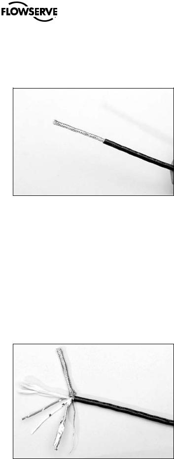
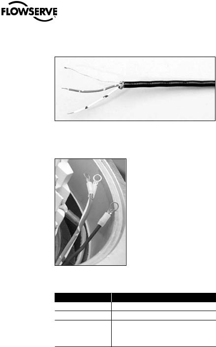
1.Remove 2 to 3 in. (5 to 8 cm) of the outer plastic jacket as shown in Figure 3.15. Do not cut or nick the drain wire or the insulated conductors.
Figure 3.15 – Removing outer plastic jacket
2.Separate the cable parts. Unbraid the braided shield and peel back the foil shield to the same point where the outer jacket was removed as shown in Figure 3.16.
3.Cut away the braided shield and the foil shield. Strip the insulation from the conductors approximately 1/2 inch (1 cm) as shown in Figure 3.17.
4.Apply heat shrink tubing to insulate the drain wire and to provide stress relief to the cable.
5.Install ring tongue connectors as shown in Figure 3.18.
a CAUTION: Do not melt the insulation.
6.Connect the network cables to the MX actuator terminal block per Table 3.4 and appropriate wiring diagram. Table 3.3 details a connection for the loop topology.
Figure 3.16 – Separating cable parts
27
flowserve.com
Limitorque MX Electronic Actuator FCD LMENIM2306-06 – 10/13
Figure 3.17 – Stripping conductors and applying heat shrink tubing
Figure 3.18 – Ring tongue connectors
Table 3.4 – Loop topology connections
Terminal Block Number DDC
4DATA-A1* (-)
5DATA-A1 (+)
14 |
DATA-A2* (-) |
|
|
13 |
DATA-A2 (+) |
|
|
3 |
Surge Protection |
In terms of voltage, DATA is negative with respect to DATA*.
NOTE: Surge protection must be grounded to be effective.
NOTE: Ground each segment of the cabling at only one point to prevent ground loops, which can affect system performance. Verify the actuator is properly grounded.
Limitorque defines an effective local earth ground as the M3 taps on the housing next to the terminal block. See figure 3.21.
NOTE: Safety ground may not be disturbed.
28NOTE: Shielding is not sufficient to prevent induction of stray voltages onto signal leads from the power lines. A network wiring diagram for a loop is shown in Figure 3.20.

Limitorque MX Electronic Actuator FCD LMENIM2306-06 – 10/13
After installation is complete and prior to operation, inspect the network cable and its connection to each field unit for the following:
There should not be:
•Nicks in the insulation—this can cause a short to the grounded shield.
•Cut strands in a stranded conductor—this can cause a poor connection and eventually an open circuit.
•Cable armor shorted to the cable shield/drain wire—this may not be at ground potential and could be subject to lightning surges.
•Shield/drain wire grounded at more than one end of each cable segment (the section between each adjacent actuator on the loop). This will avoid ground loop problems.
•Ground/earth connection except at true ground potential and effective at all times.
3.3.8 Foundation Fieldbus Installation
Ensure that the Foundation Fieldbus cable type is Belden 3076F, or another cable that is within 5% of the following specifications.
•Characteristic impedance: 100 ohms @ 31.25 kHz
•Resistance, each wire: 7.32 ohms/1000 ft
•Attenuation: 0.914 dB/1000 ft @ 39 kHz
•Capacitative Unbalance: 3.6 pF/ft
Using other cables may result in decrease of internodal distance and/or an increase in communication error.
Particular care should be taken when terminating twisted-pair shielded cables in a FF control network. Avoid nicks, cuts, or abrasions in the insulation of data communication cables, since this may result in inadvertent ground connection. Also, excess cable should be cut, not coiled or looped, to prevent noise induction into the network.
Cable Preparation
Prepare the network cable for connection to the MX actuator terminal block as follows in Figure 3.15 through 3.18. Table 3.5 details connections for Foundation Fieldbus.
Table 3.5 – Foundation fieldbus connections
Terminal Block Number |
FF Function |
4DATA (-)
5DATA (+)
The shield must be connected to ground or earth at only one place. The cable shield is generally grounded at the power conditioner.
Reference the Fieldbus Foundation Application Guide 31.25 kbit/s Wiring and Installation guide for more information on network wiring.
aCAUTION: Strip stranded conductors carefully; do not damage the strands. This will weaken the conductor. Do not nick conductors when stripping away the insulation. Nicking stresses the conductor and can cause the conductor to break. This type of damage may not be apparent and failure can occur later without warning.
29
flowserve.com

Limitorque MX Electronic Actuator FCD LMENIM2306-06 – 10/13
3.3.9 Network Wiring – Profibus DP/PA Installation
Profibus DP is based on RS 485 communication. The standard EN 50170 specifies the cable for use with Profibus DP.
The following specifications need to be fulfilled by the Profibus cable:
Table 3.6 – Profibus cable specifications
Parameter |
|
Type – Profibus DP |
Impedance |
|
135 to 165 ohm/3 to 20 MHz |
|
||
|
|
|
Capacity |
|
< 30 pF/m |
|
|
|
Resistance |
|
< 110 ohm/km |
|
|
|
Wire gauge |
|
> 0.64 mm |
|
|
|
Conductor area |
|
> 0.34 mm2 |
The Profibus DP cable is a shielded twisted pair cable.
In general, there are two different types of cables available. The most commonly used cable has solid wire for the Profibus line. When there is a need for more flexiblity (bending) and higher environmental resistance, a cable with stranded wire for the Profibus line and special jackets shall be used. Limitorque recommends the use of:
• Belden 3079A Specifications, 22 AWG, shielded, solid two conductor
Key Specifications
•Capacitance/ft = 8.5 pF
•Nominal Impedance (ohms) – 150.0
Network Wiring - Profibus PA
Please refer to IEC 61158 & ANSI/ISA S.50.02 Part 2-1992 for network wiring guidelines. Refer to Table 3.5 for connections.
3.3.10 Network Wiring – DeviceNet
DeviceNet is a CAN-based protocol that uses five wires including a shield. Two of the conductors are used for 24 VDC power and up to 8 amps (4 amps for NEC Class 2) may be passed along the hi-way from a suitable power source. Two conductors are used for the CAN bus signals, CAN_H and CAN_L, which are usually smaller in diameter. Flowserve recommends Belden 3082A cable for connecting to a DeviceNet network. The specifications for this cable are preferred.
Table 3.7 – DeviceNet cable specifications
|
Belden |
AWG (Stranding) |
Insulation |
Nominal |
Nom |
Nominal |
Test |
Maximum |
|
|
dia. Inches |
material |
Impedance |
Frequency |
Attenuation |
||||
|
Part No. |
O.D. |
Capacitance |
||||||
|
|
Nom. DCR |
(color code) |
|
(ohms) |
|
(MHz) |
dB/100ft |
|
|
|
2 – 15 AWG (19 x 28) |
Power pair |
|
|
|
|
|
|
|
|
3.6 ohm/1000 ft |
|
|
|
|
|
||
|
|
(Black/Red) |
|
|
|
0.125 |
0.13 |
||
|
|
11.8 ohm/km |
|
|
|
||||
|
3082A |
|
12.2 mm |
120 |
12.0 pF/ft |
0.5 |
0.25 |
||
|
|
|
|||||||
|
2 – 18 AWG (19 x 30) |
Data pair |
|
|
|
1 |
1.36 |
||
|
|
|
|
|
|||||
|
|
|
|
|
|
|
|||
|
|
6.9 ohm/1000 ft |
|
|
|
|
|
||
|
|
(Blue/White) |
|
|
|
|
|
||
|
|
22.7 ohm/km |
|
|
|
|
|
||
|
|
|
|
|
|
|
|
||
|
|
|
|
|
|
|
|
|
|
|
|
2 – 22 AWG (19 x 34) |
Power pair |
|
|
|
|
|
|
|
|
17.5 ohm/1000 ft |
|
|
|
|
|
||
|
|
(Black/Red) |
|
|
|
0.125 |
0.29 |
||
|
|
57.4 ohm/km |
|
|
|
||||
|
3084A |
|
7.2 mm |
120 |
12.0 pF/ft |
0.5 |
0.50 |
||
|
|
|
|||||||
30 |
2 – 18 AWG (19 x 36) |
Data pair |
1 |
1.70 |
|||||
|
|
|
|
||||||
|
|
28.0 ohm/1000 ft |
|
|
|
|
|
||
|
|
(Blue/White) |
|
|
|
|
|
||
|
|
91.9 ohm/km |
|
|
|
|
|
||
|
|
|
|
|
|
|
|
||
|
|
|
|
|
|
|
|
|
 Loading...