


NM
USER INSTRUCTIONS
NM centrifugal pump
Multi-stage, single suction and radial joint plan pump type
centrifugal pump
PCN=71576289 – 11/09 (E) Original instructions.
Installation
Operation
Maintenance

NM USER INSTRUCTIONS ENGLISH 71576289 - 11/09
Page 2 of 48
CONTENTS
PAGE
1 INTRODUCTION AND SAFETY ...........................4
1.1
G
ENERAL
.........................................................4
1.2
CE
MARKING AND APPROVALS
...........................4
1.3
D
ISCLAIMER
......................................................4
1.4
C
OPYRIGHT
......................................................4
1.5
D
UTY CONDITIONS
............................................4
1.6
S
AFETY
............................................................5
1.7
N
AMEPLATE AND SAFETY LABELS
.......................8
1.8
S
PECIFIC MACHINE PERFORMANCE
....................8
2 TRANSPORT AND STORAGE ...........................10
2.2
H
ANDLING
......................................................10
2.4
S
TORAGE
.......................................................12
2.5
R
ECYCLING AND END OF PRODUCT LIFE
............12
3 PUMP DESCRIPTION.........................................12
3.1
C
ONFIGURATIONS
...........................................12
3.2
N
OMENCLATURE
.............................................13
4 INSTALLATION....................................................14
4.1
L
OCATION
.......................................................14
4.2
F
OUNDATION
..................................................14
4.3
G
ROUTING
......................................................15
4.4
I
NITIAL ALIGNMENT
..........................................15
4.5
P
IPING
...........................................................16
4.6
E
LECTRICAL CONNECTIONS
.............................17
4.7
F
INAL SHAFT ALIGNMENT CHECK
.......................18
4.8
P
ROTECTION SYSTEMS
....................................18
5 COMMISSIONING, START-UP, OPERATION AND
SHUTDOWN...........................................................18
5.1
P
RE
-
COMMISSIONING PROCEDURE
...................18
5.2
D
IRECTION OF ROTATION
.................................19
I
F MAINTENANCE WORK HAS BEEN
CARRIED OUT TO THE SITE
'
S ELECTRICITY SUPPLY
,
THE
DIRECTION OF ROTATION SHOULD BE RE
-
CHECKED AS
ABOVE IN CASE THE
...............................................19
5.4
P
RIMING AND AUXILIARY SUPPLIES
...................19
5.5
S
TARTING THE PUMP
.......................................20
5.6
R
UNNING THE PUMP
........................................20
5.7
S
TOPPING AND SHUTDOWN
..............................22
5.8
H
YDRAULIC
,
MECHANICAL AND ELECTRICAL DUTY
............................................................................22
5.9
P
UMPS FOR
F
OOD
U
SE OR
P
OTABLE
W
ATER
...23
PAGE
6 MAINTENANCE...................................................23
6.1
G
ENERAL
........................................................23
6.2
M
AINTENANCE SCHEDULE
................................24
6.3
S
PARE PARTS
..................................................29
6.4
R
ECOMMENDED SPARES AND CONSUMABLE ITEMS
............................................................................29
6.5
D
ISASSEMBLY
.................................................29
7 FAULTS; CAUSES AND REMEDIES ..................31
8 PARTS LIST AND DRAWINGS ...........................32
8.1
S
ECTIONAL DRAWINGS
....................................32
8.2
S
ECTIONAL DRAWINGS PART LIST
.....................42
8.3
G
ENERAL ARRANGEMENT DRAWING
.................47
9 CERTIFICATION .................................................47
10 OTHER RELEVANT DOCUMENTATION AND
MANUALS...............................................................47
10.1
S
UPPLEMENTARY
U
SER
I
NSTRUCTIONS
..........47
10.2
C
HANGE NOTES
............................................47
10.3
A
DDITIONAL SOURCES OF INFORMATION
.........47

NM USER INSTRUCTIONS ENGLISH 71576289 - 11/09
Page 3 of 48
INDEX
PAGE
Additional sources (10.3).......................................47
Alignment of shafting (see 4.2, 4.4 and 4.7)
ATEX marking (1.6.4.2) ...........................................7
CE marking and approvals (1.2)..............................4
Certification (9) ......................................................47
Change notes (10.2)..............................................47
Cleaning prior to operation (5.9.1) ........................23
Commissioning, start-up, operation (5) .................18
Compliance, ATEX (1.6.4.1)....................................6
Configurations (3.1) ...............................................12
Copyright (1.4).........................................................4
Direction of rotation (5.1) .......................................18
Disassembly (6.5)..................................................29
Discharge piping (4.5.3) .......................................17
Disclaimer (1.3)........................................................4
Dismantling (see 6.5, Disassembly)......................29
Drawings (8.1) .......................................................32
Duty conditions (1.5)................................................4
Electrical connections (4.6) ...................................17
End of product life (2.5) .........................................12
Faults; causes and remedies (7) ...........................31
Final checks (4.5.4) ..............................................17
First pump start up (5.5.2) ....................................20
Foundation (4.2) ....................................................14
Forces and moments (see 4.5.1)...........................16
General arrangement drawing (8.3) ......................47
Gland packing (6.2.5) ............................................27
Grouting (4.3).........................................................15
Guarding (5.3)........................................................19
Handling (2.2) ........................................................10
Hydraulic, mechanical and electrical duty (5.8).....22
Inspection (6.2.2 and 6.2.3)...................................26
Installation (4) ........................................................14
Internal coating (6.2.6)...........................................29
Lifting (2.3).............................................................11
Location (4.1).........................................................14
Lubrication (5.1.1)..................................................18
Maintenance (6).....................................................23
Maintenance schedule (6.2) ..................................24
Mechanical seal (6.2.4) .........................................27
Nomenclature (3.2)................................................13
Nameplate (1.7.1)....................................................8
Operating limits (see 3.1) ......................................12
Ordering spare parts (6.3.1) ..................................29
Parts lists (8.2).......................................................42
Piping (4.5) ............................................................16
Protection systems (4.8)........................................18
Pump masses (2.2.2) ............................................11
Receipt and unpacking (2.1)..................................10
Recommended fill quantities (see 6.2.1.1 and
6.2.1.2)...................................................................26
Recommended grease lubricants (see 6.2.1.1) ....25
Recommended oil lubricants (see 6.2.1.2)............26
Recommended spares (6.4) ..................................29
Recycling (2.5).......................................................12
Replacement parts (see 6.3 and 6.4)....................29
PAGE
Running the pump (5.6).........................................20
Safety action (1.6.3).................................................5
Safety labels (1.7.2).................................................8
Safety markings (1.6.1)............................................5
Safety, protection systems (see 1.6 and 4.8)
Sectional drawings (8.1) ........................................32
Sound level (see 1.9, Noise level)...........................9
Sources, additional information (10.3)...................47
Spare parts (6.3)....................................................29
Specific machine performance (1.8)........................8
Standard maintenance (6.2.1) ..............................24
Starting the pump (5.5)..........................................20
Stop/start frequency (5.6.6) ...................................22
Stopping and shutdown (5.7).................................22
Storage, pump (2.4)...............................................12
Storage, spare parts (6.3.2)...................................29
Suction piping (4.5.2) ............................................17
Supplementary manuals or information sources ...47
Thermal expansion (4.4.1) ....................................15
Transport and storage (2) .....................................10
Trouble-shooting (see 7)........................................30
Vibration (5.6.5) .....................................................21
NM USER INSTRUCTIONS ENGLISH 71576289 - 11/09
Page 4 of 48
1 INTRODUCTION AND SAFETY
1.1 General
These instructions must always be kept
close to the product's operating location or
directly with the product.
Flowserve’s products are designed, developed and
manufactured with state-of-the-art technologies in
modern facilities. The unit is produced with great
care and commitment to continuous quality control,
utilizing sophisticated quality techniques, and safety
requirements.
Flowserve is committed to continuous quality
improvement and being at service for any further
information about the product in its installation and
operation or about its support products, repair and
diagnostic services.
These instructions are intended to facilitate
familiarization with the product and its permitted use.
Operating the product in compliance with these
instructions is important to help ensure reliability in
service and avoid risks. The instructions may not
take into account local regulations; ensure such
regulations are observed by all, including those
installing the product. Always coordinate repair
activity with operations personnel, and follow all
plant safety requirements and applicable safety and
health laws and regulations.
These instructions must be read prior to
installing, operating, using and maintaining the
equipment in any region worldwide. The
equipment must not be put into service until all
the conditions relating to safety noted in the
instructions, have been met. Failure to follow
and apply the present user instructions is
considered to be misuse. Personal injury,
product damage, delay or failure caused by
misuse are not covered by the Flowserve
warranty.
1.2 CE marking and approvals
It is a legal requirement that machinery and
equipment put into service within certain regions of
the world shall conform with the applicable CE
Marking Directives covering Machinery and, where
applicable, Low Voltage Equipment, Electromagnetic
Compatibility (EMC), Pressure Equipment Directive
(PED) and Equipment for Potentially Explosive
Atmospheres (ATEX).
Where applicable the Directives and any additional
Approvals cover important safety aspects relating to
machinery and equipment and the satisfactory
provision of technical documents and safety
instructions. Where applicable this document
incorporates information relevant to these Directives
and Approvals.
To confirm the Approvals applying and if the product is
CE marked, check the serial number plate markings
and the Certification. (See section 9, Certification.)
1.3 Disclaimer
Information in these User Instructions is believed
to be reliable. In spite of all the efforts of Flowserve
Pump Division to provide sound and all necessary
information the content of this manual may appear
insufficient and is not guaranteed by Flowserve as
to its completeness or accuracy.
Flowserve manufactures products to exacting
International Quality Management System Standards
as certified and audited by external Quality Assurance
organizations. Genuine parts and accessories have
been designed, tested and incorporated into the
products to help ensure their continued product quality
and performance in use. As Flowserve cannot test
parts and accessories sourced from other vendors the
incorrect incorporation of such parts and accessories
may adversely affect the performance and safety
features of the products. The failure to properly select,
install or use authorized Flowserve parts and
accessories is considered to be misuse. Damage or
failure caused by misuse is not covered by the
Flowserve warranty. In addition, any modification of
Flowserve products or removal of original components
may impair the safety of these products in their use.
1.4 Copyright
All rights reserved. No part of these instructions may
be reproduced, stored in a retrieval system or
transmitted in any form or by any means without
prior permission of Flowserve.
1.5 Duty conditions
This product has been selected to meet the
specifications of your purchaser order. The
acknowledgement of these conditions has been sent
separately to the Purchaser. A copy should be kept
with these instructions.
The product must not be operated beyond
the parameters specified for the application. If
there is any doubt as to the suitability of the
product for the application intended, contact
Flowserve for advice, quoting the serial number.
If the conditions of service on your purchase order
are going to be changed (for example liquid
pumped, temperature or duty) it is requested that the
user seeks the written agreement of Flowserve
before start up.
NM USER INSTRUCTIONS ENGLISH 71576289 - 11/09
Page 5 of 48
1.6 Safety
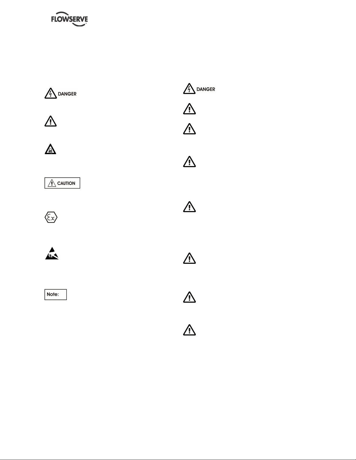
1.6.1 Summary of safety markings
These User Instructions contain specific safety
markings where non-observance of an instruction
would cause hazards. The specific safety markings
are:
This symbol indicates electrical safety
instructions where non-compliance will involve a
high risk to personal safety or the loss of life.
This symbol indicates safety instructions where
non-compliance would affect personal safety and
could result in loss of life.
This symbol indicates “hazardous substances
and toxic fluid” safety instructions where non-
compliance would affect personal safety and could
result in loss of life.
This symbol indicates safety
instructions where non-compliance will involve some
risk to safe operation and personal safety and would
damage the equipment or property.
This symbol indicates explosive atmosphere
zone marking according to ATEX. It is used in safety
instructions where non-compliance in the hazardous
area would cause the risk of an explosion.
This symbol is used in safety instructions to
remind not to rub non-metallic surfaces with a dry
cloth; ensure cloth is damp. It is used where non-
compliance in the hazardous area would cause the
risk of an explosion.
This sign is not a safety symbol but indicates
an important instruction in the assembly process.
1.6.2 Personnel qualification and training
All personnel involved in the operation, installation,
inspection and maintenance of the unit must be
qualified to carry out the work involved. If the
personnel in question do not already possess the
necessary knowledge and skill, appropriate training
and instruction must be provided. If required the
operator may commission the manufacturer/supplier
to provide applicable training.
Always coordinate repair activity with operations and
health and safety personnel, and follow all plant
safety requirements and applicable safety and health
laws and regulations.
1.6.3 Safety action
This is a summary of conditions and actions to
prevent injury to personnel and damage to the
environment and to equipment. For products
used in potentially explosive atmospheres
section 1.6.4 also applies.
NEVER DO MAINTENANCE WORK
WHEN THE UNIT IS CONNECTED TO POWER
GUARDS MUST NOT BE REMOVED WHILE
THE PUMP IS OPERATIONAL
DRAIN THE PUMP AND ISOLATE
PIPEWORK BEFORE DISMANTLING THE PUMP
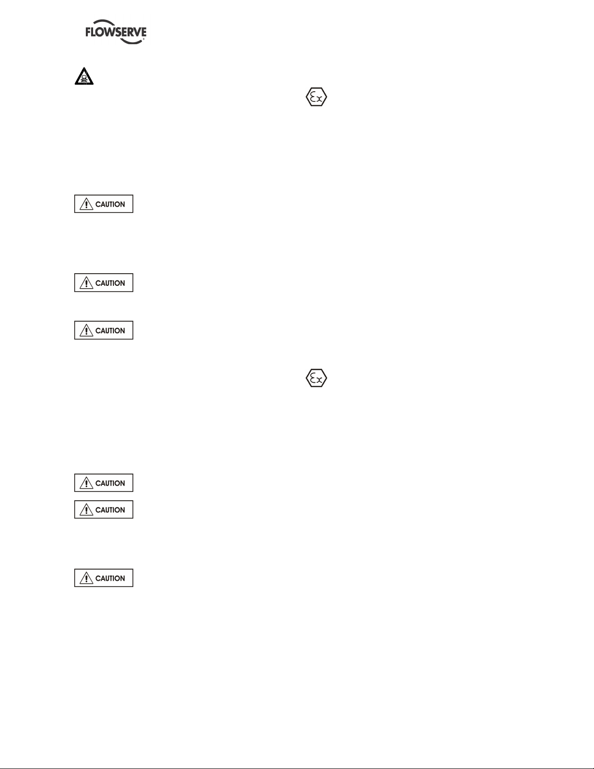
The appropriate safety precautions should be taken
where the pumped liquids are hazardous.
FLUORO-ELASTOMERS (When fitted.)
When a pump has experienced temperatures over
250 ºC (482 ºF), partial decomposition of fluoro-
elastomers (example: Viton) will occur. In this
condition these are extremely dangerous and skin
contact must be avoided.
HANDLING COMPONENTS
Many precision parts have sharp corners and the
wearing of appropriate safety gloves and equipment
is required when handling these components. To lift
heavy pieces above 25 kg (55 lb) use a crane
appropriate for the mass and in accordance with
current local regulations.
THERMAL SHOCK
Rapid changes in the temperature of the liquid within
the pump can cause thermal shock, which can result
in damage or breakage of components and should
be avoided.
NEVER APPLY HEAT TO REMOVE
IMPELLER
Trapped lubricant or vapour could cause an
explosion.
HOT (and cold) PARTS
If hot or freezing components or auxiliary heating
supplies can present a danger to operators and
persons entering the immediate area action must be
taken to avoid accidental contact. If complete
protection is not possible, the machine access must
be limited to maintenance staff only, with clear visual
warnings and indicators to those entering the
immediate area. Note: bearing housings must not be
insulated and drive motors and bearings may be hot.
If the temperature is greater than 68 °C (155 °F)
or below -5 °C (23 °F) in a restricted zone, or
exceeds local regulations, action as above shall
be taken.
NM USER INSTRUCTIONS ENGLISH 71576289 - 11/09
Page 6 of 48
HAZARDOUS LIQUIDS
When the pump is handling hazardous liquids care
must be taken to avoid exposure to the liquid by
appropriate sitting of the pump, limiting personnel
access and by operator training. If the liquid is
flammable and/or explosive, strict safety procedures
must be applied.
Gland packing must not be used when pumping
hazardous liquids.
PREVENT EXCESSIVE EXTERNAL
PIPE LOAD
Do not use pump as a support for piping. Do not
mount expansion joints, unless allowed by
Flowserve in writing, so that their force, due to
internal pressure, acts on the pump flange.
ENSURE CORRECT LUBRICATION
(See section 5, Commissioning, startup, operation
and shutdown.)
START THE PUMP WITH OUTLET
VALVE PART OPENED
(Unless otherwise instructed at a specific point in the
User Instructions.)
This is recommended to minimize the risk of
overloading and damaging the pump motor at full or
zero flow. Pumps may be started with the valve
further open only on installations where this situation
cannot occur. Pump outlet valve shall may need to
be adjusted to comply with the duty following the
run-up process. (See section 5, Commissioning
start-up, operation and shutdown.)
NEVER RUN THE PUMP DRY
INLET VALVES TO BE FULLY OPEN
WHEN PUMP IS RUNNING
Running the pump at zero flow or below the
recommended minimum flow continuously will cause
damage to the seal.
DO NOT RUN THE PUMP AT
ABNORMALLY HIGH OR LOW FLOW RATES
Operating at a flow rate higher than normal or at a
flow rate with no backpressure on the pump may
overload the motor and cause cavitations. Low flow
rates may cause a reduction in pump/bearing life,
overheating of the pump, instability and
cavitations/vibration.
1.6.4 Products used in potentially explosive
atmospheres
The following instructions for pumps and pump
units when installed in potentially explosive
atmospheres must be followed to help ensure
explosion protection.
The terminology and procedures ensure that the
installed pump is in compliance with the European
Directive 94/9/EC, known as the ATEX Directive, which
is mandatory in Europe and may also be specified in
other countries. Where applicable, both electrical and
non-electrical equipment must meet the requirements
94/9/EC.
Even if the installation is in a region where ATEX is not
the applicable regulation, the general measures
described shall be followed to ensure safe operation.
The measures are explained under the headings of:
• Avoiding excessive surface temperature.
• Preventing build up of explosive mixtures.
• Preventing the generation of sparks.
• Preventing leakages.
• Maintaining the pump to avoid hazard.
1.6.4.1 Scope of compliance
Use equipment only in the zone for which it is
appropriate. Always check that the driver, drive
coupling assembly, seal and pump equipment are
suitably rated and/or certified for the classification of
the specific atmosphere in which they are to be
installed.
Where Flowserve has supplied only the bare shaft
pump, the Ex rating applies only to the pump. The
party responsible for assembling the pump set shall
select the coupling, driver and any additional
equipment, with the necessary CE Declaration of
Conformity establishing it is suitable for the area in
which it is to be installed.
The output from a variable frequency drive (VFD) can
cause additional heating affects in the motor and so, for
pumps sets with a VFD, the ATEX Certification for the
motor must state that it is covers the situation where
electrical supply is from the VFD. This particular
requirement still applies even if the VFD is in a safe
area.
NM USER INSTRUCTIONS ENGLISH 71576289 - 11/09
Page 7 of 48
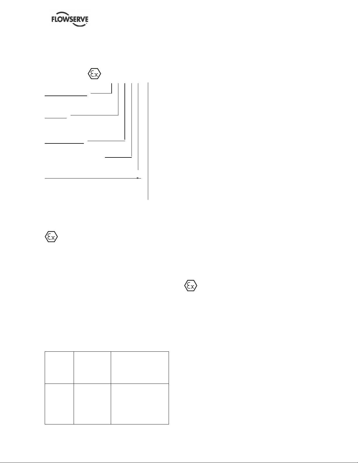
1.6.4.2 Marking
An example of ATEX equipment marking is shown
below. The actual classification of the pump will be
engraved on the nameplate.
II 2 GD c IIC 135 ºC (T4)
Equipment Group
I = Mining
II = Non-mining
Category
2 or M2 = High level protection
3 = normal level of protection
Gas and/or Dust
G = Gas; D= Dust
c = Constructional safety
(in accordance with EN13463-5)
Gas Group (Equipment Category 2 only)
IIA – Propane (typical)
IIB – Ethylene (typical)
IIC – Hydrogen (typical)
Maximum surface temperature (Temperature Class)
(see section 1.6.4.3)
1.6.4.3 Avoiding excessive surface temperatures
ENSURE THE EQUIPMENT TEMPERATURE
CLASS IS SUITABLE FOR THE HAZARD ZONE
Pumps have a temperature class as stated in the
ATEX Ex rating on the nameplate. These are based
on a maximum ambient of 40 °C (104 °F); refer to
Flowserve for higher ambient temperatures.
The surface temperature on the pump is influenced
by the temperature of the liquid handled. The
maximum permissible liquid temperature depends
on the temperature class and must not exceed the
values in the table that follows.
The temperature rise at the seals, bearings and due
to the minimum permitted flow rate is taken into
account in the temperatures stated.
Temperature
class to
prEN 13463-1
Maximum
surface
temperature
permitted
Temperature limit of liquid
handled (* depending on
material and construction
variant - check which is
lower)
T6
T5
T4
T3
T2
T1
85 °C (185 °F)
100 °C (212 °F)
135 °C (275 °F)
200 °C (392 °F)
300 °C (572 °F)
450 °C (842 °F)
Consult Flowserve
Consult Flowserve
115 °C (239 °F) *
180 °C (356 °F) *
275 °C (527 °F) *
400 °C (752 °F) *
The responsibility for compliance with the
specified maximum liquid temperature is with the
plant operator.
Temperature classification “Tx” is used when the
liquid temperature varies and the pump could be
installed in different hazardous atmospheres. In this
case the user is responsible for ensuring that the
pump surface temperature does not exceed that
permitted in the particular hazardous atmosphere.
If an explosive atmosphere exists during the
installation, do not attempt to check the direction of
rotation by starting the pump unfilled. Even a short
run time may give a high temperature resulting from
contact between rotating and stationary
components. Furthermore, confinement of liquid in
the pump and pipes must be avoided (valve closed).
If the liquid heats up this may cause excessive
pressure and lead to bursting of pump components.
Where there is any risk of the pump being run against
a closed valve generating high liquid and casing
external surface temperatures it is recommended that
users fit an external surface temperature protection
device.
Avoid mechanical, hydraulic or electrical overload by
using motor overload trips, temperature monitor or a
power monitor and make routine vibration monitoring
checks.
In dirty or dusty environments, regular checks must
be made and dirt removed from areas around close
clearances, bearing housings and motors.
1.6.4.4 Preventing the build up of explosive
mixtures
ENSURE PUMP IS PROPERLY FILLED AND
VENTED AND DOES NOT RUN DRY.
Ensure pump and relevant suction and discharge
pipeline system is totally filled with liquid at all times
during the pump operation, so that an explosive
atmosphere is prevented. In addition it is essential to
make sure that seal chambers, auxiliary shaft seal
systems and any heating and cooling systems are
properly filled.
If the operation of the system cannot avoid this
condition the fitting of an appropriate dry run
protection device is recommended (eg liquid
detection or power monitor).
To avoid potential hazards from fugitive emissions of
vapour or gas to atmosphere the surrounding area
must be well ventilated.
NM USER INSTRUCTIONS ENGLISH 71576289 - 11/09
Page 8 of 48
1.6.4.5 Preventing sparks
To prevent a potential hazard from mechanical
contact, the coupling guard must be non-sparking.
To avoid the potential hazard from random induced
current generating a spark the ground contact on the
baseplate must be used.
Avoid electrostatic charge: do not rub non-
metallic surfaces with a dry cloth, ensure cloth is
damp.
Where applicable the coupling must be selected to
comply with 94/9/EC and correct alignment must be
maintained.
Additional requirements for metallic pumps on
non-metallic baseplates.
When metallic components are fitted on a non-
metallic baseplate they must be individually earthed
(grounded).
1.6.4.6 Preventing leakage
The pump must only be used to handle liquids
for which it has been approved to have the correct
corrosion resistance.
Avoid entrapment of liquid in the pump and associated
piping due to closing of suction and discharge valves,
which could cause dangerous excessive pressures to
occur if there is heat input to the liquid. This can occur
if the pump is stationary or running.
Bursting of liquid containing parts due to freezing
must be avoided by draining or protecting the pump
and ancillary systems.
Where there is the potential hazard of a loss of a
seal barrier fluid or external flush, the fluid must be
monitored.
If leakage of liquid to atmosphere can result in a
hazard, the installation of a liquid detection device is
recommended.
1.6.4.7 Maintenance to avoid the hazard
CORRECT MAINTENANCE IS REQUIRED
TO AVOID POTENTIAL HAZARDS WHICH GIVE A
RISK OF EXPLOSION
The responsibility for compliance with
maintenance instructions is with the plant
operator.
To avoid potential explosion hazards during
maintenance, the tools, cleaning and painting
materials used must not give rise to sparking or
adversely affect the ambient conditions. Where there
is a risk from such tools or materials; maintenance
must be conducted in a safe area.
It is recommended that a maintenance plan and
schedule is adopted. (See section 6, Maintenance.)
1.7 Nameplate and safety labels
1.7.1 Nameplate
For details of nameplate, see the Declaration of
Conformity, or separate documentation included with
these User Instructions.
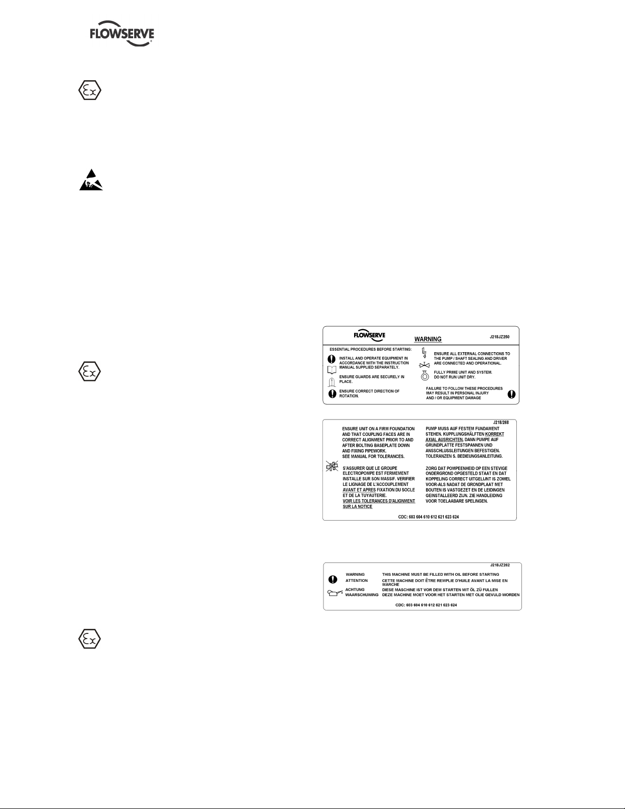
1.7.2 Safety labels
Oil lubricated units only:
1.8 Specific machine performance
For performance parameters see section 1.5, Duty
conditions. When the contract requirement specifies
these to be incorporated into User Instructions these
are included here. Where performance data has
been supplied separately to the purchaser these
should be obtained and retained with these User
Instructions if required.
NM USER INSTRUCTIONS ENGLISH 71576289 - 11/09
Page 9 of 48
1.9 Noise level
Attention must be given to the exposure of
personnel to the noise, and local legislation will
define when guidance to personnel on noise
limitation is required, and when noise exposure
reduction is mandatory. This is typically 80 to 85
dBA.
The usual approach is to control the exposure time
to the noise or to enclose the machine to reduce
emitted sound. You may have already specified a
limiting noise level when the equipment was
ordered, however if no noise requirements were
defined, then attention is drawn to the following table
to give an indication of equipment noise level so that
you can take the appropriate action in your plant.
Pump noise level is dependent on a number of
operational factors, flow rate, pipework design and
acoustic characteristics of the building, and so the
values given are subject to a 3 dBA tolerance and
cannot be guaranteed.
Similarly the motor noise assumed in the “pump and
motor” noise is that typically expected from standard
and high efficiency motors when on load directly
driving the pump. Note that a motor driven by an
inverter may show an increased noise at some
speeds.
If a pump unit only has been purchased for fitting
with your own driver then the “pump only” noise
levels in the table should be combined with the level
for the driver obtained from the supplier. Consult
Flowserve or a noise specialist if assistance is
required in combining the values.
It is recommended that where exposure approaches
the prescribed limit, then site noise measurements
should be made.
The values are in sound pressure level L
pA
at 1 m
(3.3 ft) from the machine, for “free field conditions
over a reflecting plane”.
For estimating sound power level L
WA
(re 1 pW) then
add 17 dBA to the sound pressure value.
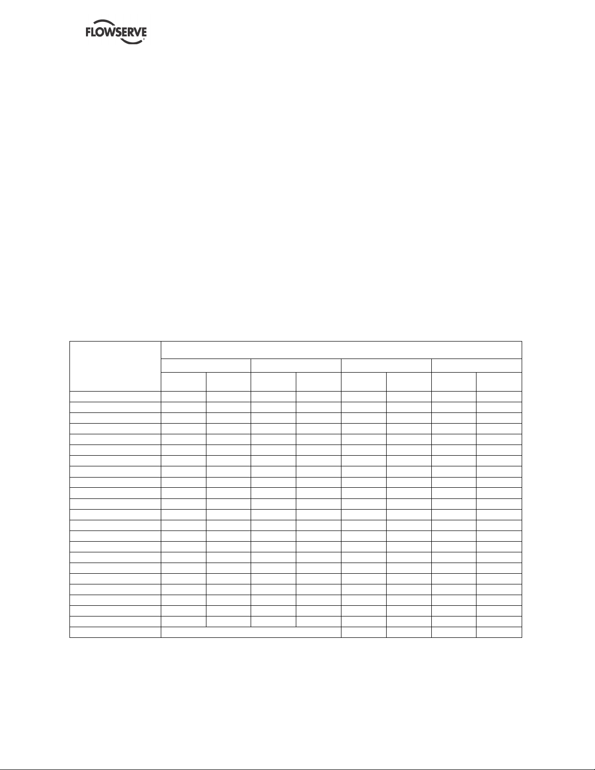
Typical sound pressure level L
pA
at 1 m reference 20 µPa, dBA
3 550 r/min 2 900 r/min 1 750 r/min 1 450 r/min
Motor size
and speed
kW (hp)
Pump
only
Pump and
motor
Pump
only
Pump and
motor
Pump
only
Pump and
motor
Pump
only
Pump and
motor
<0.55(<0.75) 72 72 64 65 62 64 62 64
0.75 (1) 72 72 64 66 62 64 62 64
1.1 (1.5) 74 74 66 67 64 64 62 63
1.5 (2) 74 74 66 71 64 64 62 63
2.2 (3) 75 76 68 72 65 66 63 64
3 (4) 75 76 70 73 65 66 63 64
4 (5) 75 76 71 73 65 66 63 64
5.5 (7.5) 76 77 72 75 66 67 64 65
7.5 (10) 76 77 72 75 66 67 64 65
11(15) 80 81 76 78 70 71 68 69
15 (20) 80 81 76 78 70 71 68 69
18.5 (25) 81 81 77 78 71 71 69 71
22 (30) 81 81 77 79 71 71 69 71
30 (40) 83 83 79 81 73 73 71 73
37 (50) 83 83 79 81 73 73 71 73
45 (60) 86 86 82 84 76 76 74 76
55 (75) 86 86 82 84 76 76 74 76
75 (100) 87 87 83 85 77 77 75 77
90 (120) 87 88 83 85 77 78 75 78
110 (150) 89 90 85 87 79 80 77 80
150 (200) 89 90 85 87 79 80 77 80
200 (270)
1 1 1 1
85 87 83 85
300 (400) 87 90 85 86
1 The noise level of machines in this range will most likely be of values which require noise exposure control, but typical values are inappropriate.
Note: for 1 180 and 960 r/min reduce 1 450 r/min values by 2 dBA. For 880 and 720 r/min reduce 1 450 r/min values by 3 dBA.

NM USER INSTRUCTIONS ENGLISH 71576289 - 11/09
Page 10 of 48
In areas where the staff has to intervene, remember
that when the level of the sound pressure is:
• below 70 dBA: it is not necessary to take special
precautions.
• above 70 dBA: people working continuously in
the machine room must be supplied with
protective devices against noise.
• below 85 dBA: no particular measures need to
be taken for casual visitors staying in the room
during a limited period.
• above 85 dBA: the room must be considered as
a dangerous area because of the noise and a
warning sign must be fixed at each entry
warning the people coming into the room, even
for a short period, that they must wear hearing
protection.
• above 105 dBA: special hearing protection
adapted to this noise level and to the spectral
noise components must be installed and a
warning sign to this effect erected at each entry.
The staff in the room must wear ear protection.
Make sure that the noise, which travels through the
walls and windows, does not generate too high
noise levels in the machine room's surroundings.
2 TRANSPORT AND STORAGE
2.1 Consignment receipt and unpacking
Immediately after receipt of the equipment it must be
checked against the delivery and shipping
documents for its completeness and that there has
been no damage in transportation.
Any shortage and or damage must be reported
immediately to Flowserve Pump Division and
received in writing within one month of receipt of the
equipment. Later claims cannot be accepted.
Check any crate, boxes and wrappings for any
accessories or spare parts that may be packed
separately with the equipment or attached to
sidewalls of the box or equipment.
Each product has a unique serial number. Check
that this number corresponds with that advised and
always quote this number in correspondence as well
as when ordering spare parts or further accessories.
2.2 Handling
2.2.1 General instructions concerning handling
Boxes, crates, pallets or cartons may be unloaded
using forklift vehicles or slings dependent on their
size and construction. See 2.3.1 for positioning of
slings.
To lift heavy pieces above 25 kg (55 lb), use a winch
adapted to the mass and in accordance with the
current local regulations.
To lift machines or pieces with one or several
suspension rings, only use hooks and chains in
compliance with the local regulations concerning
safety. Never put cables, chains or ropes directly on
or in the suspension rings. Cables, chains or lifting
ropes must never present excessive bending.
Never bend the lifting hooks, suspension rings,
chains, etc., which should only be made to endure
stresses within, calculated limits. Remember that the
capacity of a lifting device decreases when the
direction of the lifting force direction makes an angle
with the device axis.
To increase the safety and the efficiency of the lifting
device, all the lifting elements must be as
perpendicular as possible. If necessary a lifting
beam can be placed between the winch and the
load.
When heavy pieces are lifted up, never stay or work
under the load or in the area, which could be in the
path of the load if it were to swing or fall away.
Never leave a load hanging from a winch. The
acceleration or the slowing-down of lifting equipment
must stay in the safety limits for the staff.
A winch must be positioned in such a way that the
load will be raised perpendicularly. Where possible
necessary precautions must be taken to avoid the
swing of the load, using for example two winches
making approximately the same angle, below 30°,
with the vertical.
NM USER INSTRUCTIONS ENGLISH 71576289 - 11/09
Page 11 of 48
2.2.2 Pump masses
All masses are in kg:
MASS OF BARE SHAFT PUMPS ACCORDING TO STAGE NUMBER
PUMP TYPES
2 3 4 5 6 7 8 9 10 11 12
32 NM 45 50 55 60 65 70 75 80 85 90 95
40 NM 56 65 74 83 92 101 110 119 128
50 NM 82 92 102 112 122 132 142 152
65 NM 111 123 135 147 159 171 183
80 NM 146 165 184 203 222 241
100 NM 245 285 325 365 405 445 485 525
125 NM 466 509 552 595 638 681 724 767 810
150 NM 646 756 864 973 1082 1191 1300 1409 1518 1627 1736
200 NM 1048 1190 1332 1474 1616 1758 1900 2042 2184 2326
201 NM 1300 1500 1700 1900 2100
102 NM 250 289 328 367 406 445 484 523 562
122 NM 575 650 725 800 875
152 NM 820 940 1060 1180 1300
202 NM 1000 1200 1400 1600
252 NM 1800 2120 2440 2760
352 NM 3900 4475 5050
All motors (for masses see the motor
description plate) must be handled with a winch.
For masses above 25 kg (55 lb), manual
handling is forbidden.
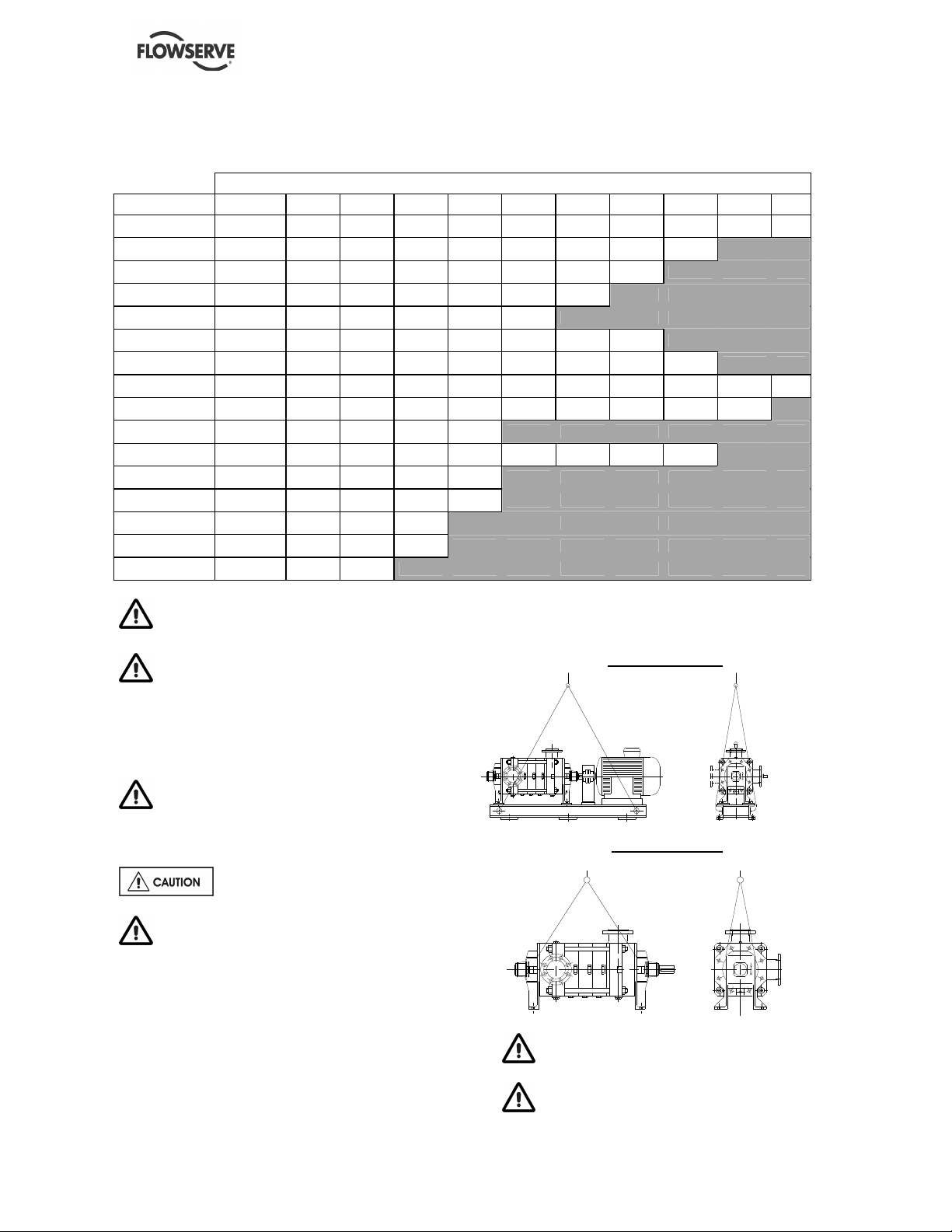
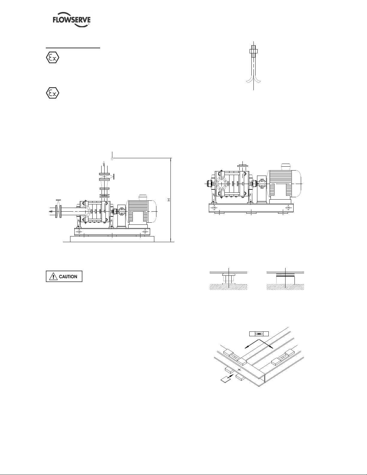
2.3 Lifting
2.3.1 Slinging of motor pumps units
Use handling means in accordance with
motor pump unit mass mentioned on the CE plate.
For the masses of the pumps bare end of shaft
see table § 2.2.2 and nameplate.
To avoid distortion, the pump unit
should be lifted as shown.
A crane must be used for all pump sets in
excess of 25kg (55 Ib). Fully trained personnel
must carry out lifting, in accordance with local
regulations.
Motor pump unit
Bareshaft pump
When handling always wear gloves, safety
boots and an industrial safety helmet.
For masses above 25 kg (55 lb), manual
handling is forbidden.
NM USER INSTRUCTIONS ENGLISH 71576289 - 11/09
Page 12 of 48
2.4 Storage
Store the pump in a clean, dry
location away from vibration. Leave piping
connection covers in place to keep dirt and other
foreign material out of pump casing. Turn pump at
intervals to prevent brinelling of the bearings and
the seal faces, if fitted, from sticking.
Do not store pumps starting on the fan guard.
The pump may be stored as above for up to 6
months. Consult Flowserve for preservative
actions when a longer storage period is needed.
2.5 Recycling and end of product life
At the end of the service life of the product or its
parts, the relevant materials and parts should be
recycled or disposed of using an environmentally
acceptable method and local regulations. If the
product contains substances which are harmful to
the environment, these should be removed and
disposed of in accordance with current regulations.
This also includes the liquids and or gases in the
"seal system" or other utilities.
Make sure that hazardous substances or
toxic fluid are disposed of safely and that the
correct personal protective equipment is used. The
safety specifications must be in accordance with
the current regulations at all times.
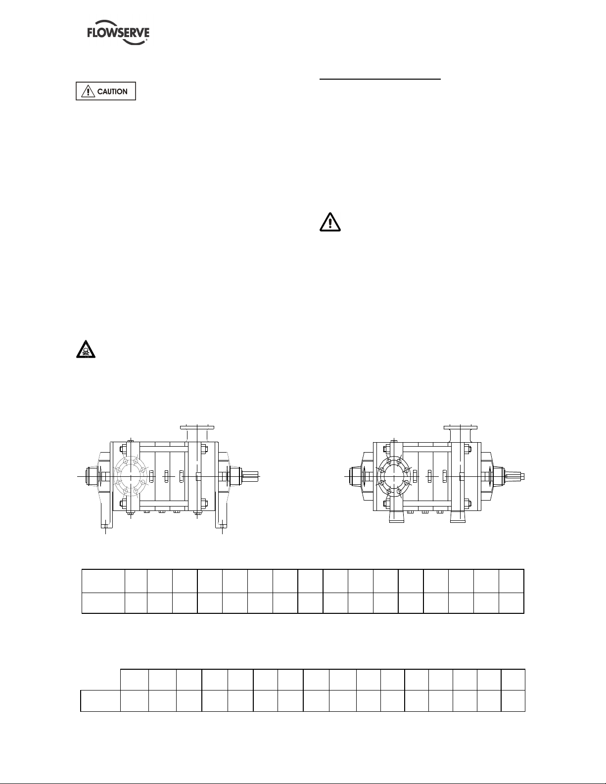
3 PUMP DESCRIPTION
3.1 Configurations
The multi-stage centrifugal pump is designed for
the pumping of cold water or all clear liquids which
are not solid and liquid mixtures, non-corrosive,
non-abrasive or non-explosive when in contact
with the pump motor unit and its working parts
(Important: for other liquids consult FLOWSERVE
for beforehand advice).
The NM type pump is a centrifugal, multi-stage,
single suction and radial joint plan pump.
The pump must be stored in a non-explosive,
ventilated location, sheltered from bad weather,
dust and vibrations.
The reliability of the delivered machine can only be
ensured if it is used according to the conditions
given in this manual. The maximum values
specified in this manual must never be exceeded.
• Maximum working pressure at discharge
Lamellar
Cast Iron
32
NM
40
NM
50
NM
65
NM
80
NM
100
NM
125
NM
150
NM
200
NM
201
NM
102
NM
122
NM
152
NM
202
NM
252
NM
352
NM
Pressure
in bar
35 35 35 35 38 40* 60 40* 40* 45 25 25 30 35 40 40
* For cast iron with spheroidal graphite: 60 bars
• Maximum working pressure at suction
32
NM
40
NM
50
NM
65
NM
80
NM
100
NM
125
NM
150
NM
200
NM
201
NM
102
NM
122
NM
152
NM
202
NM
252
NM
352
NM
Pressure
in bar
10 10 10 10 10 16 16 16 16 16 10 10 10 10 16 16
NM USER INSTRUCTIONS ENGLISH 71576289 - 11/09
Page 13 of 48
• Maximum pumped fluid temperature
- With a stuffing box without cooling ....105 °C
- With a stuffing box and cooling..........140 °C
for the pumps 32, 40, 50, 65, 80, 100, 125,
150, 200 and 201 NM.
- With a mechanical seal without cooling
............................................................. 80 °C
- With a mechanical seal and cooling
......................................................Consult us
• Minimum pumped fluid temperature.... -10 °C
•
Maximum solid suspension ................. 50 g/m
3
• Density................................................. 1
• Viscosity .............................................. 1 mm²/s
• Frequency .............. 50 Hz (1450 - 2900 min
-1
)
................................ 60 Hz (1750 - 3500 min
-1
)
• Maximum number of stages (according to speed of rotation)
Maximum number of stages
Speed
min
-1
32
NM
40
NM
50
NM
65
NM
80
NM
100
NM
125
NM
150
NM
200
NM
201
NM
102
NM
122
NM
152
NM
202
NM
252
NM
352
NM
3500 10 7 6 6 5
4 6
3*
2900 12 10 9 8 7
6 9
5
1750 12 10 9 8 7
8 9
10
6 9 6 7
4 7 5 4 4 4
1450 12 10 9 8 7 9 10
9 12 8 11
6 10 6 6 5 5 4*
* With impeller in bronze
In heavy type: Realization, which needs Ductile
cast iron.
The maximum speed is shown on
the pump nameplate.
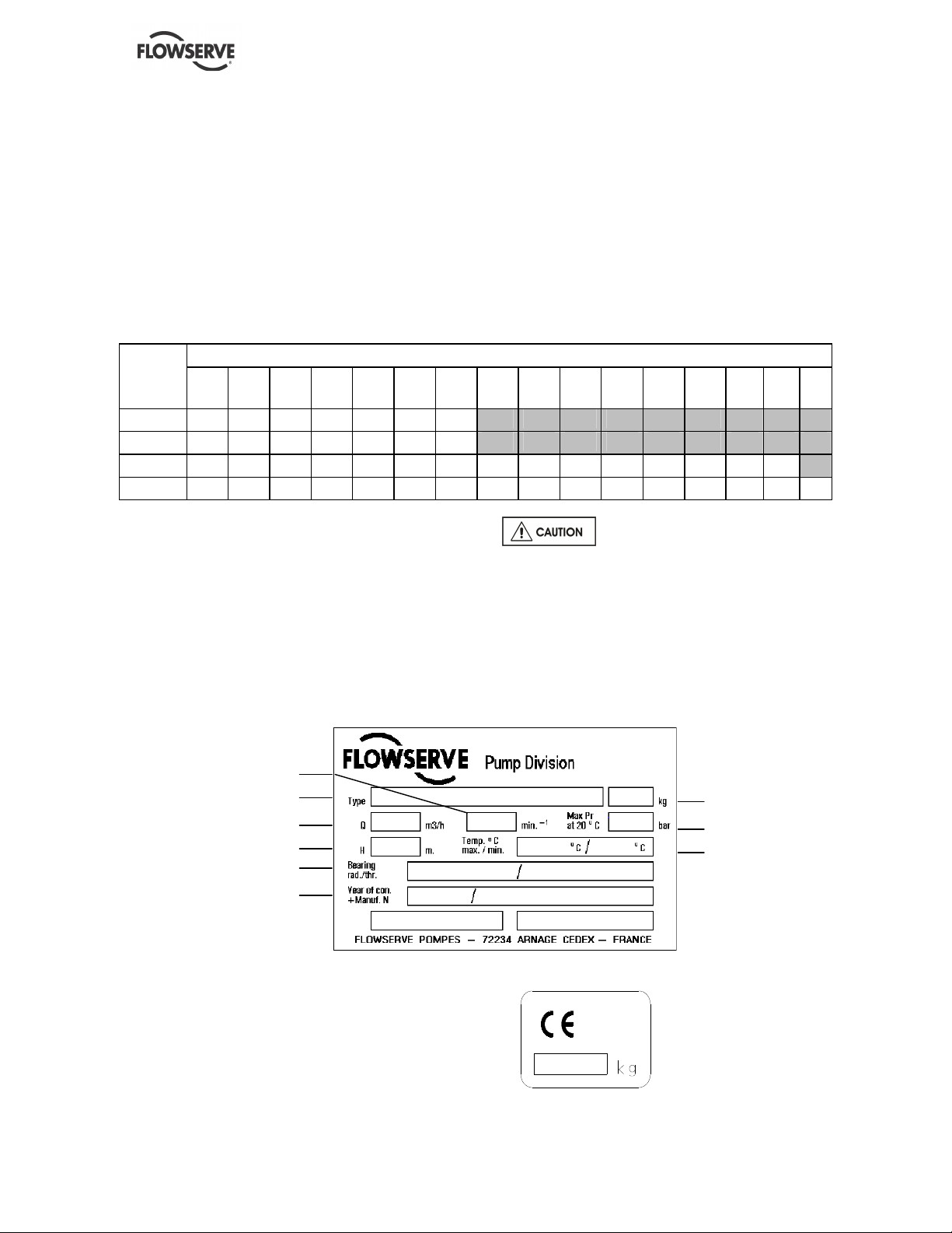
3.2 Nomenclature
Characteristics shown on the nameplate fixed on the pump are as shown below:
Each pump is supplied with the following nameplate:
Each pump unit is supplied with the following nameplate:
Mass of the set
Pump type
Speed of rotation
Flow rate
Year of construction +
Manufacture number
Head
Radial/thrust bearing
Mass
Maximum admissible
Pressure at 20 °C
Maximum / minimum
temperature
NM USER INSTRUCTIONS ENGLISH 71576289 - 11/09
Page 14 of 48
4 INSTALLATION
Equipment operated in hazardous locations
must comply with the relevant explosion protection
regulations. See section 1.6.4, Products used in
potentially explosive atmospheres.
All equipment must be grounded.
4.1 Location
The pump should be located to allow room for
access, ventilation, maintenance and inspection with
ample headroom for lifting and should be as close as
practicable to the supply of liquid to be pumped.
4.2 Foundation
There are many methods of installing
pump units to their foundations. The correct method
depends on the size of the pump unit, its location
and noise vibration limitations. Non-compliance with
the provision of correct foundation and installation
may lead to failure of the pump and, as such, would
be outside the terms of the warranty.
The base plate should be mounted onto a firm
foundation, either an appropriate thickness of quality
concrete or sturdy steel framework. It should NOT
be distorted or pulled down onto the surface of the
foundation, but should be supported to maintain the
original alignment.
Anchor bolts must be in accordance with the foot
bolt holes. Use anchor bolts of accepted standards
and sufficient to ensure seave fitting in the
foundation. Particularly, this applies to individual
plates where the anchor bolts have to withstand the
driving torque.
NF E 27 811
Provide sufficient space in the foundation to
accommodate the anchor bolts. If necessary,
provide concrete risers.
Usually the pump and its drive are mounted on a
common base plate. If not, individual base plates
underneath each machine foot shall be installed.
Base plates are to be fully grouted.
4.2.1 Setting the base plate for anchoring
a) Clean the foundation surface thoroughly.
b) Put shims on the foundation surface (approx 20-
25 mm thick), one on each side of the bolt hole
(as an alternative, leveling screws can be used).
c) Lay the base plate and level in both directions
with extra shims. The base plate should be level
to within 0.5 mm per 1 m.
d) If anchor bolts have been pre-cast in the
foundation slightly tighten the anchor bolts.
Otherwise let them hang in the foundation holes.
NM USER INSTRUCTIONS ENGLISH 71576289 - 11/09
Page 15 of 48
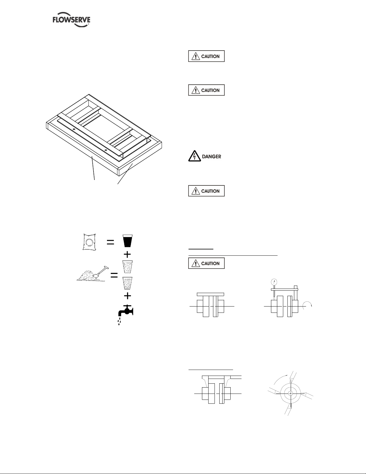
4.3 Grouting
4.3.1 Base plate grouting
a) Prepare the site for grouting. Before grouting
clean the foundation surface thoroughly and
provide external barriers as shown:
barriers
b) Prepare grouting product (concrete, resin) in
accordance with manufacturers' instructions.
c) Use grouting products with anti-shrinking
components.
d) To grout up to the required level. Polish
surfaces. Take necessary precautions to avoid
air bubbles.
e) Lay-down the barrier, break external angles, and
polish the different surfaces.
f) After grout starts to cure, definitively tighten
anchor bolts.
g) Control the alignment such as described as
follows.
4.4 Initial alignment
Before connecting the couplings
verify the motor rotation direction.
4.4.1 Thermal expansion
The pump and motor will normally
have to be aligned at ambient temperature and
should be corrected to allow for thermal expansion
at operating temperature. In pump installations
involving high liquid temperatures, the unit should be
run at the actual operating temperature, shut down
and the alignment checked immediately.
4.4.2 Alignment methods
Ensure pump and driver are isolated
electrically and the half couplings are disconnected.
Ensure that the pump pipework, suction and
discharge, is disconnected.
The alignment MUST be checked.
Although the pump will have been aligned at the
factory it is most likely that this alignment will have
been disturbed during transportation or handling. If
necessary, align the motor to the pump, not the
pump to the motor.
Alignment
Parallelism and concentricity check:
Check the alignment at three or four
points, before pipeworks assembly.
with a rule
with a comparator
Admissible margin for a motor with roller bearings:
= 0.15 mm parallel checking
= 0.1 mm angular checking
Angular checking:
with a sliding rule
with a caliper gauge
 Loading...