


USER INSTRUCTIONS
WORTHINGTON®
LR, LRV, LLR and LR-S
Horizontal, split case, volute type centrifugal pumps for water and general service
PCN=71569088 08-10 (E) (Based on C953KH013) Original instructions
Installation
Operation
Maintenance
 These instructions must be read prior to installing, operating, using and maintaining this equipment.

LR, LRV, LLR and LR-S USER INSTRUCTIONS ENGLISH 71569088 08-10
CONTENTS |
|
|
|
PAGE |
|
1 INTRODUCTION AND SAFETY............................ |
4 |
|
1.1 |
General ........................................................... |
4 |
1.2 |
CE marking and approvals.............................. |
4 |
1.3 |
Disclaimer ....................................................... |
4 |
1.4 |
Copyright......................................................... |
4 |
1.5 |
Duty conditions................................................ |
4 |
1.6 |
Safety .............................................................. |
5 |
1.7 |
Safety labels summary.................................... |
8 |
1.8 |
Specific machine performance........................ |
8 |
1.9 |
Noise level....................................................... |
9 |
2 TRANSPORT AND STORAGE............................ |
10 |
|
2.1 |
Consignment receipt and unpacking............. |
10 |
2.2 |
Handling ........................................................ |
10 |
2.3 |
Lifting............................................................. |
10 |
2.4 |
Storage.......................................................... |
10 |
2.5 |
Recycling and end of product life.................. |
10 |
3 PUMP DESCRIPTION.......................................... |
11 |
|
3.1 |
Configurations ............................................... |
11 |
3.2 |
Name nomenclature...................................... |
11 |
3.3 |
Design of major parts .................................... |
11 |
3.4 |
Performance and operating limits ................. |
12 |
4 INSTALLATION.................................................... |
12 |
|
4.1 |
Location......................................................... |
12 |
4.2 |
Part assemblies............................................. |
12 |
4.3 |
Foundation .................................................... |
12 |
4.4 |
Grouting ........................................................ |
13 |
4.5 |
Initial alignment ............................................. |
13 |
4.6 |
Piping ............................................................ |
14 |
4.7 |
Final shaft alignment check .......................... |
17 |
4.8 |
Electrical connections ................................... |
17 |
4.9 |
Protection systems........................................ |
17 |
5 COMMISSIONING, START-UP, OPERATION |
|
|
AND SHUTDOWN ........................................... |
18 |
|
5.1 |
Pre-commissioning procedure ...................... |
18 |
5.2 |
Pump lubricants ............................................ |
19 |
5.3 |
Direction of rotation ....................................... |
20 |
5.4 |
Guarding ....................................................... |
20 |
5.5 |
Priming and auxiliary supplies ...................... |
20 |
5.6 |
Starting the pump.......................................... |
20 |
5.7 |
Running the pump......................................... |
21 |
5.8 |
Stopping and shutdown................................. |
22 |
5.9 |
Hydraulic, mechanical and electrical duty..... |
22 |
|
|
PAGE |
|
6 MAINTENANCE ................................................... |
22 |
||
6.1 |
|
General ......................................................... |
22 |
6.2 |
|
Maintenance schedule.................................. |
23 |
6.3 |
|
Spare parts.................................................... |
25 |
6.4 |
|
Recommended spares |
|
|
|
and consumable items ................................. |
25 |
6.5 |
Tools required ............................................... |
26 |
|
6.6 |
|
Fastener torques........................................... |
26 |
6.7 |
|
Renewal clearances ..................................... |
26 |
6.8 |
|
Disassembly ................................................. |
26 |
6.9 |
|
Examination of parts ..................................... |
29 |
6.10 Assembly .................................................... |
29 |
||
7 FAULTS; CAUSES AND REMEDIES.................... |
34 |
||
8 PARTS LISTS AND DRAWINGS ......................... |
36 |
||
8.1 |
|
Sectional drawings – LR single entry |
|
|
|
impeller, grease lubricated, gland packed.... |
36 |
8.2 |
|
Sectional drawings – LR double entry |
|
|
|
impeller, grease lubricated, gland packed.... |
38 |
8.3 |
|
Sectional drawings – LLR grease |
|
|
|
lubricated, gland packed .............................. |
40 |
8.4 |
|
Sectional drawings – LR-S double entry |
|
|
|
impeller, grease lubricated, gland packed.... |
42 |
8.5 |
|
Sectional drawings – LRV double entry |
|
|
|
impeller, grease lubricated thrust bearing, |
|
|
|
component mechanical seal, silicon |
|
|
|
carbide bearing............................................. |
44 |
8.6 |
|
General arrangement drawing...................... |
46 |
8.7 |
|
Interchangeability charts............................... |
46 |
9 CERTIFICATION .................................................. |
47 |
||
10 OTHER RELEVANT DOCUMENTATION |
|
||
AND MANUALS................................................ |
47 |
||
10.1 |
Supplementary User Instructions ............... |
47 |
|
10.2 Change notes ............................................. |
47 |
||
10.3 |
Additional sources of information................ |
47 |
|
Page 2 of 48 |
FLOWSERVE.COM |

LR, LRV, LLR and LR-S USER INSTRUCTIONS ENGLISH 71569088 08-10
INDEX |
|
|
PAGE |
Additional sources (10.3) ......................................... |
47 |
Alignment of shafting (4.3, 4.5 and 4.7) |
|
Assembly (6.10)....................................................... |
29 |
ATEX marking (1.6.4.2) ............................................. |
7 |
CE marking and approvals (1.2)................................ |
4 |
Certification (9) ........................................................ |
47 |
Change notes (10.2) ................................................ |
47 |
Clearances (6.7, Renewal clearances).................... |
26 |
Commissioning and operation (5)............................ |
18 |
Compliance, ATEX (1.6.4.1)...................................... |
6 |
Configurations (3.1) ................................................. |
11 |
Consumable items (6.4) .......................................... |
25 |
Copyright (1.4) ........................................................... |
4 |
Design of major parts (3.3) ...................................... |
11 |
Direction of rotation (5.3) ......................................... |
20 |
Disassembly (6.8) .................................................... |
26 |
Disclaimer (1.3).......................................................... |
4 |
Dismantling (6.8, Disassembly) ............................... |
26 |
Drawings (8) ............................................................ |
36 |
Duty conditions (1.5).................................................. |
4 |
Electrical connections (4.8) ..................................... |
17 |
End of product life (2.5) ........................................... |
10 |
Examination of parts (6.9) ....................................... |
28 |
Fastener torques (6.6) ............................................. |
26 |
Faults; causes and remedies (7) ............................. |
34 |
Forces and moments (4.6.3) ................................... |
15 |
Foundation (4.3) ...................................................... |
12 |
General arrangement drawing (8.6) ........................ |
46 |
General assembly drawings (8)............................... |
36 |
Grouting (4.4)........................................................... |
13 |
Guarding (5.4).......................................................... |
20 |
Handling (2.2) .......................................................... |
10 |
Hydraulic, mechanical and electrical duty (5.9)....... |
22 |
Inspection (6.2.1 and 6.2.2)..................................... |
23 |
Installation (4) .......................................................... |
12 |
Interchangeability charts (8.7) ................................. |
46 |
Lifting (2.3)............................................................... |
10 |
Location (4.1)........................................................... |
12 |
Lubrication (5.1.1, 5.2 and 6.2.3) |
|
Lubrication schedule (5.2.4) .................................... |
19 |
Maintenance (6)....................................................... |
22 |
Maintenance schedule (6.2) .................................... |
23 |
Name nomenclature (3.2) ........................................ |
11 |
Nameplate (1.7.1) ...................................................... |
8 |
Operating limits (3.4.1) ............................................ |
12 |
Options (8) ............................................................... |
36 |
Ordering spare parts (6.3.1) .................................... |
25 |
Part assemblies (4.2)............................................... |
12 |
Parts lists (8)............................................................ |
36 |
Performance (3.4).................................................... |
12 |
Piping (4.6) .............................................................. |
14 |
|
PAGE |
Pre-commissioning (5.1) .......................................... |
18 |
Priming and auxiliary supplies (5.5) ......................... |
20 |
Protection systems (4.9) .......................................... |
17 |
Reassembly (6.10, Assembly) ................................. |
29 |
Receipt and unpacking (2.1) .................................... |
10 |
Recommended fill quantities (see 3.4.2).................. |
12 |
Recommended grease lubricants (5.2.2) ................. |
19 |
Recommended oil lubricants (5.2.1) ........................ |
19 |
Recommended spares (6.4)..................................... |
25 |
Recycling (2.5) ......................................................... |
10 |
Renewal clearances (6.7) ........................................ |
26 |
Replacement parts (6.3 and 6.4).............................. |
25 |
Running the pump (5.7) ........................................... |
21 |
Safety action (1.6.3) ................................................... |
5 |
Safety labels (1.7.2) ................................................... |
8 |
Safety markings (1.6.1) .............................................. |
5 |
Safety, protection systems (1.6 and 4.9) |
|
Sectional drawings (8).............................................. |
36 |
Sound pressure level (1.9, Noise level) ..................... |
9 |
Sources, additional information (10.3) ..................... |
47 |
Spare parts (6.3) ...................................................... |
25 |
Specific machine performance (1.8) .......................... |
8 |
Starting the pump (5.6)............................................. |
20 |
Stop/start frequency (5.7.6)...................................... |
22 |
Stopping and shutdown (5.8) ................................... |
22 |
Storage, pump (2.4) ................................................. |
10 |
Storage, spare parts (6.3.2) ..................................... |
25 |
Supplementary manuals or information sources |
......47 |
Supplementary User Instructions (10.1)................... |
47 |
Tools required (6.5) .................................................. |
25 |
Torques for fasteners (6.6)....................................... |
26 |
Trouble-shooting (see 7) .......................................... |
34 |
Vibration (5.7.5)........................................................ |
21 |
Page 3 of 48 |
FLOWSERVE.COM |

LR, LRV, LLR and LR-S USER INSTRUCTIONS ENGLISH 71569088 08-10
1 INTRODUCTION AND SAFETY
1.1 General
 These Instructions must always be kept close to the product's operating location or directly with the product.
Flowserve products are designed, developed and manufactured with state-of-the-art technologies in modern facilities. The unit is produced with great care and commitment to continuous quality control, utilising sophisticated quality techniques and safety requirements.
Flowserve is committed to continuous quality improvement and being at service for any further information about the product in its installation and operation or about its support products, repair and diagnostic services.
These instructions are intended to facilitate familiarization with the product and its permitted use. Operating the product in compliance with these instructions is important to help ensure reliability in service and avoid risks. The instructions may not take into account local regulations; ensure such regulations are observed by all, including those installing the product. Always coordinate repair activity with operations personnel, and follow all plant safety requirements and applicable safety and health laws and regulations.
 These instructions must be read prior to installing, operating, using and maintaining the equipment in any region worldwide. The equipment must not be put into service until all the conditions relating to safety, noted in the instructions, have been met. Failure to follow and apply the present user instructions is considered to be misuse. Personal injury, product damage, delay or failure caused by misuse are not covered by the Flowserve warranty.
Where applicable, the Directives and any additional Approvals, cover important safety aspects relating to machinery and equipment and the satisfactory provision of technical documents and safety instructions. Where applicable this document incorporates information relevant to these Directives and Approvals.
To confirm the Approvals applying and if the product is CE marked, check the serial number plate markings and the Certification. (See section 9, Certification.)
1.3 Disclaimer
Information in these User Instructions is believed to be complete and reliable. However, in spite of all of the efforts of Flowserve Corporation to provide comprehensive instructions, good engineering and safety practice should always be used.
Flowserve manufactures products to exacting International Quality Management System Standards as certified and audited by external Quality Assurance organisations. Genuine parts and accessories have been designed, tested and incorporated into the products to help ensure their continued product quality and performance in use. As Flowserve cannot test parts and accessories sourced from other vendors the incorrect incorporation of such parts and accessories may adversely affect the performance and safety features of the products. The failure to properly select, install or use authorised Flowserve parts and accessories is considered to be misuse. Damage or failure caused by misuse is not covered by the Flowserve warranty. In addition, any modification of Flowserve products or removal of original components may impair the safety of these products in their use.
1.4 Copyright
All rights reserved. No part of these instructions may be reproduced, stored in a retrieval system or transmitted in any form or by any means without prior permission of Flowserve.
1.2 CE marking and approvals
It is a legal requirement that machinery and equipment put into service within certain regions of the world shall conform with the applicable CE Marking Directives covering Machinery and, where applicable, Low Voltage Equipment, Electromagnetic Compatibility (EMC), Pressure Equipment Directive (PED) and Equipment for Potentially Explosive Atmospheres (ATEX).
1.5 Duty conditions
This product has been selected to meet the specifications of your purchaser order. The acknowledgement of these conditions has been sent separately to the Purchaser. A copy should be kept with these instructions.
 The product must not be operated beyond the parameters specified for the application. If there is any doubt as to the suitability of the product for the application intended, contact Flowserve for advice, quoting the serial number.
Page 4 of 48 |
FLOWSERVE.COM |

LR, LRV, LLR and LR-S USER INSTRUCTIONS ENGLISH 71569088 08-10
If the conditions of service on your purchase order are going to be changed (for example liquid pumped, temperature or duty) it is requested that the user seeks the written agreement of Flowserve before start up.
1.6 Safety
1.6.1 Summary of safety markings
These User Instructions contain specific safety markings where non-observance of an instruction would cause hazards. The specific safety markings are:
 This symbol indicates electrical safety instructions where non-compliance will involve a high risk to personal safety or the loss of life.
 This symbol indicates safety instructions where non-compliance would affect personal safety and could result in loss of life.


 This symbol indicates “hazardous and toxic fluid” safety instructions where non-compliance would affect personal safety and could result in loss of life.
 This symbol indicates safety instructions where non-compliance will involve some risk to safe operation and personal safety and would damage the equipment or property.
 This symbol indicates explosive atmosphere zone marking according to ATEX. It is used in safety instructions where non-compliance in the hazardous area would cause the risk of an explosion.
 This symbol is used in safety instructions to remind not to rub non-metallic surfaces with a dry cloth; ensure the cloth is damp. It is used in safety instructions where non-compliance in the hazardous area would cause the risk of an explosion.
 This sign is not a safety symbol but indicates an important instruction in the assembly process.
1.6.2 Personnel qualification and training
All personnel involved in the operation, installation, inspection and maintenance of the unit must be qualified to carry out the work involved. If the personnel in question do not already possess the necessary knowledge and skill, appropriate training and instruction must be provided. If required the operator may commission the manufacturer/supplier to provide applicable training.
Always coordinate repair activity with operations and health and safety personnel, and follow all plant safety requirements and applicable safety and health laws and regulations.
1.6.3 Safety action
This is a summary of conditions and actions to help prevent injury to personnel and damage to the environment and to equipment. For products used in potentially explosive atmospheres section 1.6.4 also applies.
 NEVER DO MAINTENANCE WORK WHEN THE UNIT IS CONNECTED TO POWER
 GUARDS MUST NOT BE REMOVED WHILE THE PUMP IS OPERATIONAL
 DRAIN THE PUMP AND ISOLATE PIPEWORK BEFORE DISMANTLING THE PUMP
The appropriate safety precautions should be taken where the pumped liquids are hazardous.
 FLUORO-ELASTOMERS (When fitted.) When a pump has experienced temperatures over 250 ºC (482 ºF), partial decomposition of fluoroelastomers (example: Viton) will occur. In this condition these are extremely dangerous and skin contact must be avoided.
 HANDLING COMPONENTS
Many precision parts have sharp corners and the wearing of appropriate safety gloves and equipment is required when handling these components. To lift heavy pieces above 25 kg (55 lb) use a crane appropriate for the mass and in accordance with current local regulations.
 APPLYING HEAT TO REMOVE IMPELLER There may be occasions when the impeller has either been shrunk fit on to the pump shaft or has become difficult to remove due to products of corrosion.
If you elect to use heat to remove the impeller, it must be applied quickly to the impeller boss. TAKE
GREAT CARE!
Before applying heat ensure any residual hazardous liquid trapped between the impeller and pump shaft is thoroughly drained out through the impeller keyway to prevent an explosion or emission of toxic vapour. This must be carried out with the shaft in the vertical position. On some pump sizes a cavity exists in the impeller bore so on occasions a significant volume of liquid may drain out.
Page 5 of 48 |
FLOWSERVE.COM |

LR, LRV, LLR and LR-S USER INSTRUCTIONS ENGLISH 71569088 08-10
 THERMAL SHOCK
Rapid changes in the temperature of the liquid within the pump can cause thermal shock, which can result in damage or breakage of components and should be avoided.
 HOT (and cold) PARTS
If hot or freezing components or auxiliary heating supplies can present a danger to operators and persons entering the immediate area action must be taken to avoid accidental contact. If complete protection is not possible, the machine access must be limited to maintenance staff only, with clear visual warnings and indicators to those entering the immediate area. Note: bearing housings must not be insulated and drive motors and bearings may be hot.
If the temperature is greater than 80 ºC (175 ºF) or below -5 ºC (20 ºF) in a restricted zone, or exceeds local regulations, action as above shall be taken.


 HAZARDOUS LIQUIDS
When the pump is handling hazardous liquids care must be taken to avoid exposure to the liquid by appropriate siting of the pump, limiting personnel access and by operator training. If the liquid is flammable and/or explosive, strict safety procedures must be applied.
Gland packing must not be used when pumping hazardous liquids.
 PREVENT EXCESSIVE EXTERNAL PIPE LOAD
Do not use pump as a support for piping. Do not mount expansion joints, unless allowed by Flowserve in writing, so that their force, due to internal pressure, acts on the pump flange.
 ENSURE CORRECT LUBRICATION (See section 5, Commissioning, startup, operation and shutdown.)
 START THE PUMP WITH OUTLET VALVE PARTLY OPENED
(Unless otherwise instructed at a specific point in the User Instructions.)
This is recommended to minimize the risk of overloading and damaging the pump motor at full or zero flow. Pumps may be started with the valve further open only on installations where this situation cannot occur. The pump outlet control valve may need to be adjusted to comply with the duty following the run-up process. (See section 5, Commissioning start-up, operation and shutdown.)
 NEVER RUN THE PUMP DRY
 INLET VALVES TO BE FULLY OPEN WHEN PUMP IS RUNNING
Running the pump at zero flow or below the recommended minimum flow continuously will cause damage to the pump and mechanical seal.
 DO NOT RUN THE PUMP AT ABNORMALLY HIGH OR LOW FLOW RATES Operating at a flow rate higher than normal or at a flow rate with no back pressure on the pump may overload the motor and cause cavitation. Low flow rates may cause a reduction in pump/bearing life, overheating of the pump, instability and cavitation/vibration.
1.6.4 Products used in potentially explosive atmospheres
 Measures are required to:
∙Avoid excess temperature
∙Prevent build up of explosive mixtures
∙Prevent the generation of sparks
∙Prevent leakages
∙Maintain the pump to avoid hazard
The following instructions for pumps and pump units when installed in potentially explosive atmospheres must be followed to help ensure explosion protection. For ATEX, both electrical and non-electrical equipment must meet the requirements of European Directive 94/9/EC. Always observe the regional legal Ex requirements eg Ex electrical items outside the EU may be required certified to other than ATEX eg IECEx, UL.
1.6.4.1 Scope of compliance
 Use equipment only in the zone for which it is appropriate. Always check that the driver, drive coupling assembly, seal and pump equipment are suitably rated and/or certified for the classification of the specific atmosphere in which they are to be installed.
Where Flowserve has supplied only the bare shaft pump, the Ex rating applies only to the pump. The party responsible for assembling the ATEX pump set shall select the coupling, driver and any additional equipment, with the necessary CE Certificate/ Declaration of Conformity establishing it is suitable for the area in which it is to be installed.
The output from a variable frequency drive (VFD) can cause additional heating affects in the motor and so, for pumps sets with a VFD, the ATEX Certification for the motor must state that it is covers the situation where electrical supply is from the VFD. This particular requirement still applies even if the VFD is in a safe area.
Page 6 of 48 |
FLOWSERVE.COM |
LR, LRV, LLR and LR-S USER INSTRUCTIONS ENGLISH 71569088 08-10
1.6.4.2 Marking
An example of ATEX equipment marking is shown below. The actual classification of the pump will be engraved on the nameplate.
 II 2 GD c IIC 135 ºC (T4)
Equipment Group 
I = Mining
II = Non-mining
Category
2 or M2 = high level protection
3 = normal level of protection
Gas and/or dust
G = Gas
D = Dust
c = Constructional safety
(in accordance with EN13463-5)
Gas Group (Equipment Category 2 only)
IIA – Propane (typical)
IIB – Ethylene (typical)
IIC – Hydrogen (typical)
Maximum surface temperature (Temperature Class) (see section 1.6.4.3.)
1.6.4.3 Avoiding excessive surface temperatures
 ENSURE THE EQUIPMENT TEMPERATURE CLASS IS SUITABLE FOR THE HAZARD ZONE
Pumps have a temperature class as stated in the ATEX Ex rating on the nameplate. These are based on a maximum ambient of 40 ºC (104 ºF); refer to Flowserve for higher ambient temperatures.
The surface temperature on the pump is influenced by the temperature of the liquid handled. The maximum permissible liquid temperature depends on the temperature class and must not exceed the values in the table that follows.
Temperature class |
Maximum surface |
Temperature limit of |
to EN13463-1 |
temperature permitted |
liquid handled * |
T6 |
85 °C (185 °F) |
Consult Flowserve |
T5 |
100 °C (212 °F) |
Consult Flowserve |
T4 |
135 °C (275 °F) |
115 °C (239 °F) |
T3 |
200 °C (392 °F) |
180 °C (356 °F) |
T2 |
300 °C (572 °F) |
275 °C (527 °F) |
T1 |
450 °C (842 °F) |
400 °C (752 °F) |
*The table only takes the ATEX temperature class into consideration. Pump design or material, as well as component design or material, may further limit the maximum working temperature of the liquid.
The temperature rise at the seals and bearings and due to the minimum permitted flow rate is taken into account in the temperatures stated.
The responsibility for compliance with the specified maximum liquid temperature is with the plant operator.
Temperature classification “Tx” is used when the liquid temperature varies and the pump could be installed in different hazarous atmospheres. In this case the user is responsible for ensuring that the pump surface temperature does not exceed that permitted in the particular hazardous atmosphere.
If an explosive atmosphere exists during the installation, do not attempt to check the direction of rotation by starting the pump unfilled. Even a short run time may give a high temperature resulting from contact between rotating and stationary components.
Where there is any risk of the pump being run against a closed valve generating high liquid and casing external surface temperatures, fit an external surface temperature protection device.
Avoid mechanical, hydraulic or electrical overload by using motor overload trips, temperature monitor or a power monitor and make routine vibration monitoring checks.
In dirty or dusty environments, make regular checks and remove dirt from areas around close clearances, bearing housings and motors.
1.6.4.4 Preventing the build up of explosive mixtures
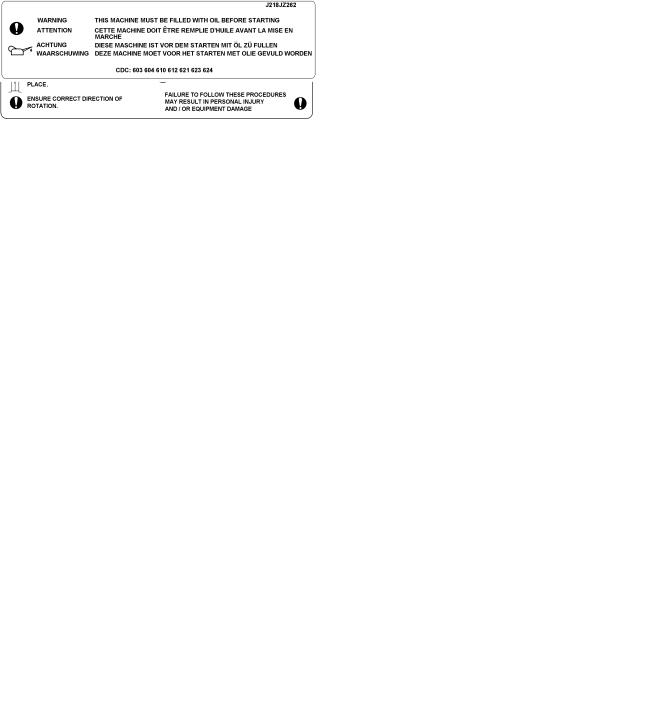
 ENSURE THE PUMP IS PROPERLY FILLED AND VENTED AND DOES NOT RUN DRY
Ensure the pump and relevant suction and discharge pipeline system is totally filled with liquid at all times during the pump operation, so that an explosive atmosphere is prevented. In addition it is essential to make sure that seal chambers, auxiliary shaft seal systems and any heating and cooling systems are properly filled.
If the operation of the system cannot avoid this condition fit an appropriate dry run protection device (for example liquid detection or a power monitor).
To avoid potential hazards from fugitive emissions of vapour or gas to atmosphere the surrounding area must be well ventilated.
Page 7 of 48 |
FLOWSERVE.COM |
LR, LRV, LLR and LR-S USER INSTRUCTIONS ENGLISH 71569088 08-10
1.6.4.5 Preventing sparks
 To prevent a potential hazard from mechanical contact, the coupling guard must be non-sparking.
To avoid the potential hazard from random induced current generating a spark, the baseplate must be properly grounded.
 Avoid electrostatic charge: do not rub non-metallic surfaces with a dry cloth; ensure cloth is damp.
For ATEX application sthe coupling must be selected to comply with 94/9/EC. Correct coupling alignment must be maintained.
Additional requirement for metallic pumps on non-metallic baseplates
When metallic components are fitted on a nonmetallic baseplate they must be individually earthed.
1.6.4.6 Preventing leakage
 The pump must only be used to handle liquids for which it has been approved to have the correct corrosion resistance.
Avoid entrapment of liquid in the pump and associated piping due to closing of suction and discharge valves, which could cause dangerous excessive pressures to occur if there is heat input to the liquid. This can occur if the pump is stationary or running.
Bursting of liquid containing parts due to freezing must be avoided by draining or protecting the pump and ancillary systems.
To avoid potential explosion hazards during maintenance, the tools, cleaning and painting materials used must not give rise to sparking or adversely affect the ambient conditions. Where there is a risk from such tools or materials, maintenance must be conducted in a safe area.
It is recommended that a maintenance plan and schedule is adopted. (See section 6, Maintenance.)
1.7 Safety labels summary
1.7.1 Nameplate
For details of nameplate, see the Declaration of Conformity, or separate documentation included with these User Instructions.
1.7.2 Safety labels
Where there is the potential hazard of a loss of a seal barrier fluid or external flush, the fluid must be monitored.
If leakage of liquid to atmosphere can result in a hazard, install a liquid detection device.
1.6.4.7 Maintenance to avoid the hazard
 CORRECT MAINTENANCE IS REQUIRED TO AVOID POTENTIAL HAZARDS WHICH GIVE A RISK OF EXPLOSION
The responsibility for compliance with maintenance instructions is with the plant operator.
Oil lubricated units only:
1.8 Specific machine performance
For performance parameters see section 1.5, Duty conditions. When the contract requirement specifies these to be incorporated into User Instructions these are included here. Where performance data has been supplied separately to the purchaser these should be obtained and retained with these User Instructions if required.
Page 8 of 48 |
FLOWSERVE.COM |

LR, LRV, LLR and LR-S USER INSTRUCTIONS ENGLISH 71569088 08-10
1.9 Noise level
Attention must be given to the exposure of personnel to the noise, and local legislation will define when guidance to personnel on noise limitation is required, and when noise exposure reduction is mandatory. This is typically 80 to 85 dBA.
The usual approach is to control the exposure time to the noise or to enclose the machine to reduce emitted sound. You may have already specified a limiting noise level when the equipment was ordered, however if no noise requirements were defined, then attention is drawn to the following table to give an indication of equipment noise level so that you can take the appropriate action in your plant.
Pump noise level is dependent on a number of operational factors, flow rate, pipework design and acoustic characteristics of the building, and so the values given are subject to a 3 dBA tolerance and cannot be guaranteed.
Similarly the motor noise assumed in the “pump and motor” noise is that typically expected from standard and high efficiency motors when on load directly driving the pump. Note that a motor driven by an inverter may show an increased noise at some speeds.
If a pump unit only has been purchased for fitting with your own driver then the “pump only” noise levels in the table should be combined with the level for the driver obtained from the supplier. Consult Flowserve or a noise specialist if assistance is required in combining the values.
It is recommended that where exposure approaches the prescribed limit, then site noise measurements should be made.
The values are in sound pressure level LpA at 1 m (3.3 ft) from the machine, for “free field conditions over a reflecting plane”.
For estimating sound power level LWA (re 1pW) then add 17 dBA to the sound pressure value.
Motor size |
|
Typical sound pressure level LpA at 1 m reference 20 µPa, dBA |
|
|
||||||
3 550 r/min |
2 900 r/min |
1 750 r/min |
|
1 450 r/min |
||||||
and speed |
|
|||||||||
kW (hp) |
Pump |
Pump and |
Pump |
Pump and |
Pump |
Pump and |
|
Pump |
Pump and |
|
|
|
only |
motor |
only |
motor |
only |
motor |
|
only |
motor |
<0.55(<0.75) |
72 |
72 |
64 |
65 |
62 |
64 |
|
62 |
64 |
|
0.75 (1) |
72 |
72 |
64 |
66 |
62 |
64 |
|
62 |
64 |
|
1.1 |
(1.5) |
74 |
74 |
66 |
67 |
64 |
64 |
|
62 |
63 |
1.5 (2) |
74 |
74 |
66 |
71 |
64 |
64 |
|
62 |
63 |
|
2.2 (3) |
75 |
76 |
68 |
72 |
65 |
66 |
|
63 |
64 |
|
3 |
(4) |
75 |
76 |
70 |
73 |
65 |
66 |
|
63 |
64 |
4 |
(5) |
75 |
76 |
71 |
73 |
65 |
66 |
|
63 |
64 |
5.5 |
(7.5) |
76 |
77 |
72 |
75 |
66 |
67 |
|
64 |
65 |
7.5 (10) |
76 |
77 |
72 |
75 |
66 |
67 |
|
64 |
65 |
|
11(15) |
80 |
81 |
76 |
78 |
70 |
71 |
|
68 |
69 |
|
15 |
(20) |
80 |
81 |
76 |
78 |
70 |
71 |
|
68 |
69 |
18.5 (25) |
81 |
81 |
77 |
78 |
71 |
71 |
|
69 |
71 |
|
22 |
(30) |
81 |
81 |
77 |
79 |
71 |
71 |
|
69 |
71 |
30 |
(40) |
83 |
83 |
79 |
81 |
73 |
73 |
|
71 |
73 |
37 |
(50) |
83 |
83 |
79 |
81 |
73 |
73 |
|
71 |
73 |
45 |
(60) |
86 |
86 |
82 |
84 |
76 |
76 |
|
74 |
76 |
55 |
(75) |
86 |
86 |
82 |
84 |
76 |
76 |
|
74 |
76 |
75 (100) |
87 |
87 |
83 |
85 |
77 |
77 |
|
75 |
77 |
|
90 (120) |
87 |
88 |
83 |
85 |
77 |
78 |
|
75 |
78 |
|
|
|
|
|
|
|
|
|
|
|
|
110 (150) |
89 |
90 |
85 |
87 |
79 |
80 |
|
77 |
80 |
|
150 |
(200) |
89 |
90 |
85 |
87 |
79 |
80 |
|
77 |
80 |
|
|
|
|
|
|
|
|
|
|
|
200 |
(270) |
1 |
1 |
1 |
1 |
85 |
87 |
|
83 |
85 |
300 |
(400) |
|
|
|
|
87 |
90 |
|
85 |
86 |
1 The noise level of machines in this range will most likely be of values which require noise exposure control, but typical values are inappropriate. Note: for 1 180 and 960 r/min reduce 1 450 r/min values by 2 dBA. For 880 and 720 r/min reduce 1 450 r/min values by 3 dBA.
Page 9 of 48 |
FLOWSERVE.COM |
LR, LRV, LLR and LR-S USER INSTRUCTIONS ENGLISH 71569088 08-10
2 TRANSPORT AND STORAGE
2.1 Consignment receipt and unpacking
Immediately after receipt of the equipment it must be checked against the delivery and shipping documents for its completeness and that there has been no damage in transportation.
Any shortage and or damage must be reported immediately to Flowserve and received in writing within one month of receipt of the equipment. Later claims cannot be accepted.
Check any crates, boxes and wrappings for any accessories or spare parts that may be packed separately with the equipment or attached to side walls of the box or equipment.
Each product has a unique serial number. Check that this number corresponds with that advised and always quote this number in correspondence as well as when ordering spare parts or further accessories.
2.2 Handling
Boxes, crates, pallets or cartons may be unloaded using fork lift vehicles or slings dependent on their size and construction.
2.3 Lifting
 A crane must be used for all pump sets in excess of 25 kg (55 lb.). Fully trained personnel must carry out lifting, in accordance with local regulations.
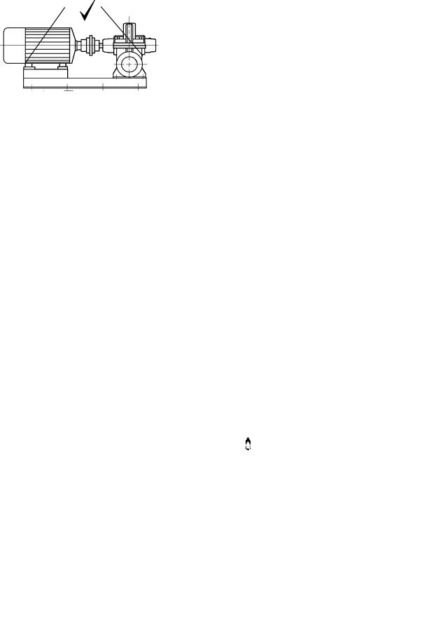
 To avoid distortion, the pump unit should be lifted as shown.
When there are no specific lifting points on the baseplate
Before lifting the driver alone, refer to the manufacturer’s instructions.
2.4 Storage
 Store the pump in a clean, dry location away from vibration. Leave piping connection covers in place to keep dirt and other foreign material out of pump casing. Turn pump at intervals to prevent brinelling of the bearings and the seal faces, if fitted, from sticking.
The pump may be stored as above for up to 6 months. Consult Flowserve for preservative actions when a longer storage period is needed.
2.5 Recycling and end of product life
At the end of the service life of the product or its parts, the relevant materials and parts should be recycled or disposed of using an environmentally acceptable method and local regulations. If the product contains substances that are harmful to the environment, these should be removed and disposed of in accordance with current regulations. This also includes the liquids and or gases that may be used in the "seal system" or other utilities.


 Make sure that hazardous substances are disposed of safely and that the correct personal protective equipment is used. The safety specifications must be in accordance with the current regulations at all times.
|
|
|
|
Page 10 of 48 |
FLOWSERVE.COM |
||
LR, LRV, LLR and LR-S USER INSTRUCTIONS ENGLISH 71569088 08-10
3 PUMP DESCRIPTION
3.1 Configurations
The LR range of pumps are horizontal split casing volute type centrifugal pumps designed for water works, drainage, general service and circulating applications. They can be used with motor, steam turbine and gasoline or diesel engine drives.
The range can have the following configurations:
LR single-stage horizontal suction and discharge nozzles. LLR two-stage horizontal suction and discharge nozzles.
LR-S single stage horizontal suction and discharge nozzles.
LRV single-stage LR horizontal suction/discharge nozzles, with vertical pump shaft.
3.2 Name nomenclature
The pump size will be engraved on the nameplate typically as below:
6LR-18S
Nominal discharge branch size
Configuration – see 3.1 above
Nominal maximum impeller diameter
Tongue and groove casing rings fitted
The typical nomenclature above is the general guide to the LR configuration description. Identify the actual pump size and serial number from the pump nameplate. Check that this agrees with the applicable certification provided.
3.3 Design of major parts
3.3.1 Pump casing
The pump has its main casing gasket axial to the shaft allowing maintenance to the rotating element by removing the top half casing. Suction and discharge branches are in the bottom half and therefore remain undisturbed.
3.3.2 Impeller
The impeller is fully shrouded and may be fitted with optional hub rings.
3.3.3 Shaft
The large diameter stiff shaft, mounted on bearings, has a keyed drive end.
3.3.4 Pump bearings and lubrication
Ball bearings are fitted as standard and may be either oil or grease lubricated.
Oil lubrication is only available where the pump shaft is horizontal.
Bearing isolators or stationary labyrinths may be fitted as an option in the bearing covers to protect the bearings.
The LRV as standard has a liquid lubricated journal bearing fitted at the non-drive end. This bearing is lubricated by pumped product or from an external clean source.
3.3.5 Bearing housing
Two grease nipples enable grease lubricated bearings to be replenished between major service intervals.
LR-S pumps have sealed for life bearings and cannot be re-greased.
For oil lubricated bearings, a constant level oiler is fitted.
3.3.6 Seal housing
The design enables one of a number of sealing options to be fitted.
3.3.7 Shaft seal
The mechanical seal(s), attached to the pump shaft, seals the pumped liquid from the environment. Gland packing may be fitted as an option on the LR, LR-S, and LLR.
3.3.8 Driver
The driver is normally an electric motor. Different drive configurations may be fitted such as internal combustion engines, turbines, hydraulic motors etc driving via couplings, belts, gearboxes, drive shafts etc.
Page 11 of 48 |
FLOWSERVE.COM |

LR, LRV, LLR and LR-S USER INSTRUCTIONS ENGLISH 71569088 08-10
3.3.9 Accessories
Accessories may be fitted when specified by the customer.
3.4 Performance and operating limits
This product has been selected to meet the specifications of your purchase order, see section 1.5.
The following data is included as additional information to help with your installation. It is typical, and factors such as temperature, materials, and seal type may influence this data. If required, a definitive statement for your particular application can be obtained from Flowserve.
3.4.1 Operating limits
Pumped liquid temperature limits *
-20 to +150 ºC (-4 to +302 ºF)
Maximum ambient temperature *
-20 to +40 ºC (-4 to +104 ºF)
Maximum soft solids in suspension *
up to 3 % by volume (refer for size limits)
Maximum pump speed |
refer to the nameplate |
* Subject to written agreement from Flowserve.
4 INSTALLATION
 Equipment operated in hazardous locations must comply with the relevant explosion protection regulations. See section 1.6.4, Products used in potentially explosive atmospheres.
4.1 Location
The pump should be located to allow room for access, ventilation, maintenance and inspection with ample headroom for lifting and should be as close as practicable to the supply of liquid to be pumped.
Refer to the general arrangement drawing for the pump set.
4.2 Part assemblies
Motors may be supplied loose on LRV pumps, typically on frame sizes 250 and above. It is the responsibility of the installer to ensure that the motor is assembled to the pump and lined up as detailed in section 4.5.2.
4.3 Foundation
 There are many methods of installing pump units to their foundations. The correct method depends on the size of the pump unit, its location and noise vibration limitations. Non-compliance with the provision of correct foundation and installation may
lead to failure of the pump and, as such, would be outside the terms of the warranty.
3.4.2 Pump and impeller data
|
Impeller |
Nominal |
Mean radial |
Approx. oil |
|
Pump |
minimum |
wear ring |
wear ring |
capacity, both |
|
size |
passage size |
diameter |
clearance |
bearings |
|
|
mm (in.) |
mm (in.) |
mm (in.) * |
litres (fl. oz.) |
|
|
|
|
|
|
|
1.5LLR-7 |
6 (0.24) |
95.25 (3.75) |
0.19 (0.007) |
|
|
1.5LLR-10 |
9 (0.35) |
0.16 (5.4) |
|||
|
|
||||
2LLR-9 |
7.5 (0.29) |
103.2 (4.06) |
|
|
|
2LLR-11 |
124.0 (4.88) |
0.22 (0.009) |
|
||
|
|
||||
3LLR-11 |
10.5 (0.41) |
139.9 (5.51) |
0.19 (6.4) |
||
|
|||||
4LLR-11 |
17 (0.67) |
157.3 (6.19) |
|
|
|
|
|
|
|
|
|
2.5LR10 |
9 (0.35) |
95.25 (3.75) |
0.19 (0.007) |
0.16 (5.4) |
|
2.5LR-13 |
13 (0.51) |
123.8 (4.88) |
|
0.17 (5.8) |
|
3LR-9 |
8 (0.31) |
103.2 (4.06) |
|
|
|
3LR-12 |
14.5 (0.57) |
|
|
0.16 (5.4) |
|
4LR-10 |
16.5 (0.65) |
|
|
|
|
4LR-11 |
18 (0.71) |
123.8 (4.88) |
|
0.17 (5.8) |
|
4LR-12 |
12 (0.47) |
|
|
||
|
|
|
|||
4LR-14 |
16 (0.63) |
|
|
0.16 (5.4) |
|
5LR-10 |
16.5 (0.65) |
|
|
||
|
|
|
|||
5LR-13 |
15 (0.59) |
139.7 (5.5) |
|
0.17 (5.8) |
|
5LR-15 |
17 (0.67) |
|
|
0.19 (6.4) |
|
5LR-19 |
168.4 (6.63) |
0.22 (0.009) |
|||
|
|
||||
|
|
|
|
||
6LR-10 |
21 (0.83) |
157.2 (6.19) |
0.16 (5.4) |
||
6LR-13 |
17.5 (0.69) |
157.2 (6.19) |
|
0.19 (6.4) |
|
6LR-16 |
|
||||
|
|
|
|
||
6LR-18 |
23.5 (0.93) |
|
|
0.21 (7.1) |
|
8LR-12 |
22 (0.87) |
190.5 (7.5) |
|
0.19 (6.4) |
|
8LR-14 |
|
|
|||
|
|
|
|
||
8LR-20 |
27 (1.06) |
|
|
|
|
10LR-14 |
44.5 (1.75) |
228.6 (9.0) |
|
0.21 (7.1) |
|
|
|
|
|
|
|
10LR-16 |
39 (1.54) |
|
|
|
|
10LR-17 |
41 (1.61) |
278 (10.95) |
|
0.28 (9.46) |
|
|
|
|
|||
10LR-18 |
22 (0.87) |
|
|||
|
|
|
|||
|
|
|
|
|
|
6LR-18S |
26.5 (1.04) |
215.9 (8.5) |
|
|
|
8LR-18S |
38 (1.50) |
247.7 (9.75) |
|
|
|
|
|
|
|
|
|
8LR-23S |
23 (0.91) |
235 (9.25) |
0.13 (0.005) |
0.47 (15.9) |
|
10LR-14S |
42.5 (1.67) |
247.7 (9.75) |
|||
10LR-18S |
57.5 (2.26) |
273.1 (10.75) |
|
|
|
12LR-14S |
58.5 (2.30) |
|
|
||
|
|
|
*May be up to 0.13 mm (0.005 in.) larger if casing ring and impeller have a tendency to gall.
 Clearances for non-metallic wear rings are smaller, typically 50 - 65% of those for the standard metallic rings shown above.
Page 12 of 48 |
FLOWSERVE.COM |
LR, LRV, LLR and LR-S USER INSTRUCTIONS ENGLISH 71569088 08-10
Ensure the following are met:
a)The baseplate should be mounted onto a firm foundation, either an appropriate thickness of quality concrete or sturdy steel framework.
(It should NOT be distorted or pulled down onto the surface of the foundation, but should be supported to maintain the original alignment.)
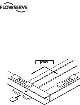
b)Install the baseplate onto packing pieces evenly spaced and adjacent to foundation bolts.
c)Level with shims between baseplate and packing pieces.
d)The pump and driver have been aligned before dispatch however the alignment of pump and motor half coupling must be checked. If this is incorrect, it indicates that the baseplate has become twisted and should be corrected by re-shimming.
e)Vertical pumps should be mounted following the practices outlined for baseplate mounted pumps. (Larger sizes may need the motor fitting after installing the pump - refer to section 4.5.2.)
f)If the pump is driven via a universal joint drive shaft there may be a requirement to offset the pump shaft with respect to the driver to optimize the universal joint drive shaft bearing life. This offset will typically be in the range 0 to 4 degrees depending on shaft design. Please consult the separate User Instructions before installation.
g)Any support for the universal joint drive shaft plummer blocks must not exhibit resonant frequencies in the range 0.8 to 1.2 N where N = pump running speed.
h)If not supplied, guarding shall be fitted as necessary to meet the requirements of ISO 12100 and EN953 and or any applicable local safety regulations.
4.4 Grouting
Where applicable, grout in the foundation bolts.
After adding pipework connections and rechecking the coupling alignment, the baseplate should then be grouted in accordance with good engineering practice. Fabricated steel, cast iron and epoxy baseplates can be filled with grout. Folded steel baseplates should be grouted to locate their packing pieces. If in any doubt, please contact your nearest service centre for advice.
Grouting provides solid contact between the pump unit and foundation, prevents lateral movement of running equipment and dampens resonant vibrations.
Foundation bolts should only be fully tightened when the grout has cured.
4.5 Initial alignment
4.5.1 Thermal expansion
 The pump and motor will normally have to be aligned at ambient temperature and should be corrected to allow for thermal expansion at operating temperature. In pump installations involving high liquid temperatures, the unit should be run at the actual operating temperature, shut down and the alignment checked immediately.
4.5.2 Alignment methods
 Ensure pump and driver are isolated electrically and the half couplings are disconnected.
 The alignment MUST be checked.
Although the pump will have been aligned at the factory it is most likely that this alignment will have been disturbed during transportation or handling. If necessary, align the motor to the pump, not the pump to the motor.
Horizontal pumps – LR, LLR and LR-S
Alignment is achieved by adding or removing shims under the motor feet and also moving the motor horizontally as required. In some cases where the alignment cannot be achieved it will be necessary to move the pump before recommencing the above procedure.
Vertical pumps – LRV
Adding or removing shims between the motor stool and the pump casing achieves alignment. The motor/motor stool assembly may also have to be moved horizontally at the interface with the pump casing, as required.
It should be noted that the motor has a spigot (rabbet) fit into the motor stool and it is therefore not possible to achieve any horizontal movement at this interface.
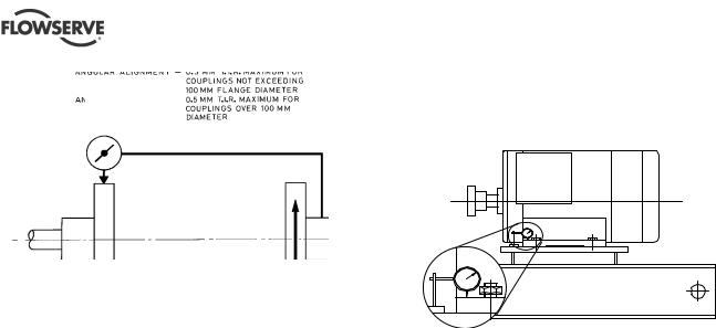
For couplings with narrow flanges use a dial indicator as shown below to check both parallel and angular alignment.
Page 13 of 48 |
FLOWSERVE.COM |
LR, LRV, LLR and LR-S USER INSTRUCTIONS ENGLISH 71569088 08-10
4.5.3Check for soft foot
Parallel
Angular
Maximum permissible misalignment at working temperature:
Parallel 0.2 mm (0.008 in.) TIR Angular 0.1 mm (0.004 in.) TIR
When checking parallel alignment, the total indicator read-out (TIR) shown is twice the value of the actual shaft displacement.
Align in the vertical plane first, then horizontally by moving motor. When performing final alignment, check for soft-foot under the driver. A TIR indicator placed on the coupling, reading in the vertical direction, should not indicate more than 0.05 mm (0.002 in.) movement when any driver foot fastener is loosened.
While the pump is capable of operating with the maximum misalignment shown above, maximum pump reliability is obtained by near perfect alignment of 0.05 to 0.10 mm (0.002 to 0.004 in.) TIR parallel and 0.05 mm (0.002 in.) per 100 mm (4 in.) of coupling flange diameter as TIR angular misalignment. This covers the full series of couplings available.
Pumps with thick flanged non-spacer couplings can be aligned by using a straight-edge across the outside diameters of the coupling hubs and measuring the gap between the machined faces using feeler gauges, measuring wedge or callipers.
When the electric motor has sleeve bearings it is necessary to ensure that the motor is aligned to run on its magnetic centreline.
 Refer to the motor manual for details.
A button (screwed into one of the shaft ends) is normally fitted between the motor and pump shaft ends to fix the axial position.
 If the motor does not run in its magnetic centre the resultant additional axial force may overload the pump thrust bearing.
This is a check to ensure that there is no undue stress on the driver holding down bolts; due to nonlevel baseplate or twisting. To check, remove all shims and clean surfaces and tighten down driver to the baseplate. Set a dial indicator as shown in sketch and loosen off the holding down bolt while noting any deflection reading on the dial test indicator - a maximum of 0.05 mm (0.002 in.) is considered acceptable but any more will have to be corrected by adding shims, for example, if the dial test indicator shows the foot lifting 0.15 mm (0.006 in.) then this is the thickness of shim to be placed under that foot. Tighten down and repeat the same procedure on all other feet until all are within tolerance
 Complete piping as below and see sections 4.7,
Final shaft alignment check, up to and including section 5, Commissioning, startup, operation and shutdown, before connecting driver and checking actual rotation.
4.6 Piping
 Protective covers are fitted to the pipe connections to prevent foreign bodies entering during transportation and installation. Ensure that these covers are removed from the pump before connecting any pipes.
4.6.1 Suction and discharge pipework
In order to minimize friction losses and hydraulic noise in the pipework it is good practice to choose pipework that is one or two sizes larger than the pump suction and discharge. Typically main pipework velocities should not exceed 2 m/s (6 ft/sec) suction and 3 m/s (9 ft/sec) on the discharge.
Take into account the available NPSH which must be higher than the required NPSH of the pump.
Page 14 of 48 |
FLOWSERVE.COM |
LR, LRV, LLR and LR-S USER INSTRUCTIONS ENGLISH 71569088 08-10
 Never use the pump as a support for piping.
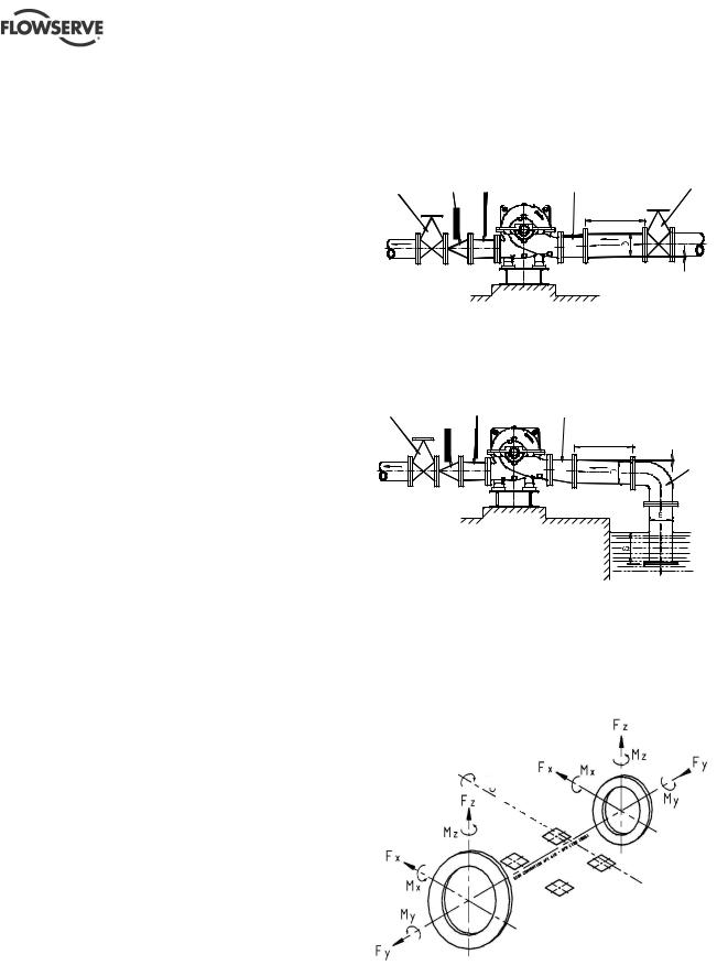
Maximum forces and moments allowed on the pump flanges vary with the pump size and type. To minimize these forces and moments that may, if excessive, cause misalignment, hot bearings, worn couplings, vibration and the possible failure of the pump casing, the following points should be strictly followed:
∙Prevent excessive external pipe load
∙Never draw piping into place by applying force to pump flange connections
∙Do not mount expansion joints so that their force, due to internal pressure, acts on the pump flange
The table in 4.6.3 summarizes the maximum forces and moments allowed on horizontal shaft pump casings. Refer to Flowserve when the pump shaft is vertical.
 Ensure piping and fittings are flushed before use.
 Ensure piping for hazardous liquids is arranged to allow pump flushing before removal of the pump.
4.6.2 Suction piping
a)The inlet pipe should be one or two sizes larger than the pump inlet bore and pipe bends should be as large a radius as possible.
b)Pipework reducers should be conical and have a maximum total angle of divergence of 15 degrees.
c)On suction lift the piping should be inclined up towards the pump inlet with eccentric reducers incorporated to prevent air locks.
d)On positive suction, the inlet piping must have a constant fall towards the pump.
e)Flow should enter the pump suction with uniform flow, to minimize noise and wear. This is particularly important on large or high-speed pumps which should have a minimum of five diameters of straight pipe on the pump suction between the elbow and inlet flange. See section 10.3, Reference 1, for more detail.
f)Inlet strainers, when used, should have a net `free area' of at least three times the inlet pipe area.
g)Do not install elbows at an angle other than perpendicular to the shaft axis. Elbows parallel to the shaft axis will cause uneven flow.
h)Except in unusual circumstances strainers are not recommended in inlet piping. If considerable foreign matter is expected a screen installed at the entrance to the wet well is preferable.
i)Fitting an isolation valve will allow easier maintenance.
j)Never throttle pump on suction side and never place a valve directly on the pump inlet nozzle.
Typical design – flooded suction
|
|
|
Concentric |
Eccentric |
Suction |
|||
Discharge |
|
|
conical |
conical |
isolating |
|||
isolating |
|
Non |
reducer |
reducer |
valve |
|||
valve |
|
return |
|
|
|
|
|
|
|
|
valve |
|
|
|
|
|
|
|
|
|
|
|
|
|
|
|
>5D
Slope up from pump suction
Note:
Ideally reducers should be limited to one pipe diameter change, ie 150 mm (6 in.) to 200 mm (8 in.). Must have a maximum total angle of divergence of 15 degrees.
Typical design – suction lift
Discharge |
|
Concentric |
Eccentric |
|
isolating |
Non |
conical |
conical |
|
valve |
return |
reducer |
reducer |
|
|
valve |
|
|
Slope down |
|
|
|
>5D |
from pump |
|
|
|
suction |
Long radius bend
Notes:
1.S = Minimum submergence >3E.
2.Ideally reducers to be limited to one pipe diameter change, ie 150 mm (6 in.) to 200 mm (8 in.). Must have a maximum total angle of divergence of 15 degrees.
4.6.3 Maximum forces and moments allowed on the pump suction and discharge flanges of horizontal shaft pumps
 Pump
Pump
axis
Discharge
Suction
See table overleaf.
Page 15 of 48 |
FLOWSERVE.COM |
 Loading...