


Installation
Instructions
Durametallic® SLM-6000, SLM-6100
Self contained cartridge medium duty slurry seal
Experience In Motion
1 Cartridge Installation Instructions
The following instruction manual is designed to simplify the installation of a typical SLM-6000 or SLM-6100 slurry seal. The SLM-6000 is a single seal with no quench port connections, the SLM-6000 QCD adds an elastomer type quench containment device (V-ring or lip seal) and 2 quench port connections to the single seal and the SLM-6100 adds a basic end face quench containment mechanical seal to make a tandem design with a circulating device and 2 quench port connections to the single seal.
By reading this manual and following its guidelines, seal performance can be improved by eliminating the chances of premature failure due to improper installation. In addition to
these instructions, consult the seal assembly drawing included for your specific seal design, materials of construction, critical dimensions, and any auxiliary piping connections.
As you go through this manual you will find some of the instructions referenced with figure numbers. These illustrations are provided to help you visualize what the instruction is trying to explain. If these instructions are followed faithfully, the seal installation will be successful, and maintenance personnel will understand the proper procedures to follow when pump adjustment is necessary.
For special problems encountered during installation, contact your nearest Flowserve Sales and Service Representative or Authorized Distributor.
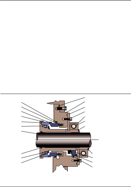
Typical Single SLM-6000 Cartridge Seal |
Figure 1 |
Stator O-ring |
Gland O-ring |
Gland |
|
Spring |
Centering Plate |
Stator |
Centering Plate Locking Screws |
Rotor |
Sleeve Collar |
Rotor O-ring |
Collar Cap Screw |
Rotor Pin |
Snap Spring |
Sleeve |
without QCD |
|
|
|
(top view) |
|
with QCD |
|
(bottom view) |
Sleeve O-ring |
Snap Ring |
Snap Ring |
QCD Stator |
Flow Guide |
V-ring |
|
QCD Stator O-ring |
2 Recommendations
To ensure that your SLM-6000 Mechanical Seal will provide you with the longest possible life, we recommend the following:
2.1New radial and thrust bearings be installed in the pump.
The images of parts shown in these instructions may differ visually from the actual parts due to manufacturing processes that do not affect the part function or quality.
2
2.2The saddle fits of the bearing assembly should not be worn.
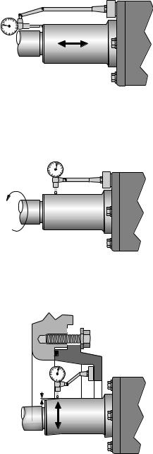
2.3The axial end float of the pump shaft must not exceed 0.25 mm (0.010"). See Figure 2.
Check Axial Shaft Travel |
Figure 2 |
0.25 mm (0.010") Maximum
Acceptable Axial Movement
2.4Shaft radial runout should be less than 0.0005 mm per mm (0.0005" per inch) of shaft/sleeve diameter. See Figure 3. Turn the shaft through 360° and observe the range of indicator movement.
Check Radial Shaft Runout |
Figure 3 |
Maximum Acceptable Radial
Run Out 0.0005 mm per mm (0.0005" per inch) of shaft diameter
2.5The shaft should deflect no more than 0.30 mm (0.012") at the seal chamber face.
See Figure 4.
Check Radial Shaft Deflection |
|
Figure 4 |
||||
|
|
|
|
|
|
|
|
|
|
|
|
|
|
|
|
|
|
|
|
|
|
|
|
|
|
|
|
|
|
|
|
|
|
|
Shaft should Deflect no more than 0.30 mm (0.012")
3
2.6Ensure that the shaft or shaft sleeve has a 1.6 mm (0.06") x 30° chamfer on the leading edge to prevent O-ring damage at seal installation.
2.7Hardened shaft sleeves must not be used when cartridge sleeve locking is accomplished by set screws bearing directly into the shaft sleeve. Any of the sleeve collars that clamp the cartridge sleeve to the shaft sleeve may be used on hardened shaft sleeves.
3General Instructions
3.1Ensure that the bearing assembly is mounted correctly (central and square) to the pump pedestal and securely fastened.
3.2Ensure that all fit locations on the pedestal are clean and free of burrs.
3.3Clean the pump shaft/sleeve surface, making sure it is clean of product and rust and has no burrs.
3.4If the pump design requires it, bolt seal adapter plate to equipment case/pedestal (hand tighten only).
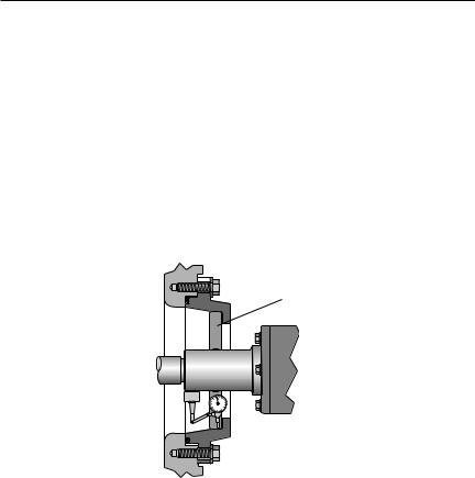
3.5Locate the seal fit of the adapter to the shaft by use of a dial indicator or centering jig.
The equipment shaft must be concentric to the seal adapter bore to within 0.38 mm
(0.015"). See Figure 5.
Center Adapter Plate to Shaft |
Figure 5 |
|
|
|
|
Centering Jig
Adapter to be Concentric with
Shaft within 0.38 mm (0.015")
3.6For adapters provided with a centering jig, simply insert the centering jig into the adapter and tighten adapter bolts alternately, adjusting the cover location until the centering jig can be removed by hand without binding.
3.7Apply a light coat of O-ring lubricant to the seal sleeve O-ring. (Silicone grease must be used with EPDM gaskets.)
Warning: Do not apply anti-seize or other lubrication to the pump shaft/sleeve. Keep the shaft/sleeve clean and dry. The use of lubricants will cause improper clamping pressure by the clamp collar.
4
 Loading...