


|
User Instructions RG Series Standard Actuator - AXENIM0122-00 12/09 |
® |
USER INSTRUCTIONS |
|
|
|
|
RG Series Standard Actuator
FCD AXENIM0122-00 12/09
Installation
Operation
Maintenance
Experience In Motion

User Instructions RG Series Standard Actuator - AXENIM0122-00 12/09
 ®
®
INDEX
1Using Flowserve Valves, Actuators and Accessories Correctly
2Installation
3Travel Stop Adjustments
4Maintenance Instructions
5Field Conversion from Fail CW to Fail CCW
6Torque Shaft
7Long Term Storage
1Using Flowserve Valves, Actuators and Accessories Correctly
1.1General usage
The following instructions are designed to assist in unpacking, installing and performing maintenance as required on FLOWSERVE products. Product users and maintenance personnel should thoroughly review this bulletin prior to installing, operating or performing any maintenance.
In most cases FLOWSERVE valves, actuators and accessories are designed for specific applications with regard to medium, pressure and temperature. For this reason they should not be used in other applications without first contacting the manufacturer.
1.2Terms concerning safety
The safety terms DANGER, WARNING, CAUTION and NOTE are used in these instructions to highlight particular dangers and/or to provide additional information on aspects that may not be readily apparent.
DANGER: indicates that death, severe personal injury and/or substantial property damage will occur if proper precautions are not taken.
WARNING: indicates that death, severe personal
|
STOP! |
injury and/or substantial property damage can occur |
|
|
|
|
|
if proper precautions are not taken. |
|
|
CAUTION: indicates that minor personal injury and/ |
|
|
or property damage can occur if proper precautions |
|
|
are not taken. |
|
|
NOTE: indicates and provides additional technical |
|
|
information, which may not be very obvious even |
2 |
|
to qualified personnel. |
|
|
Compliance with other, not particularly emphasised notes, with regard to transport, assembly, operation and maintenance and with regard to technical documentation (e.g. in the operating instruction, product documentation or on the product itself) is essential, in order to avoid faults, which in themselves might directly or indirectly cause severe personal injury or property damage.
1.3Protective clothing
FLOWSERVE products are often used in problematic applications (e.g. extremely high pressures, dangerous, toxic or corrosive mediums). In particular valves with bellows seals point to such applications. When performing service, inspection or repair operations always ensure, that the valve and actuator are depressurised and that the valve has been cleaned and is free from harmful substances. In such cases pay particular attention to personal protection (protective clothing, gloves, glasses etc.).
1.4Qualified personnel
Qualified personnel are people who, on account of their training, experience and instruction and their knowledge of relevant standards, specifications, accident prevention regulations and operating conditions, have been authorised by those responsible for the safety of the plant to perform the necessary work and who can recognise and avoid possible dangers.
1.5Installation
DANGER: Before installation check the order-no., serial-no. and/or the tag-no. to ensure that the valve/ actuator is correct for the intended application.
Do not insulate extensions that are provided for hot or cold services.
Pipelines must be correctly aligned to ensure that the valve is not fitted under tension.
Fire protection must be provided by the user.
1.6Spare parts
Use only FLOWSERVE original spare parts. FLOWSERVE cannot accept responsibility for any damages that occur from using spare parts or fastening materials from other manufactures. If FLOWSERVE products (especially sealing materials) have been on store for longer periods check these for corrosion or deterioration before using these products. Fire protection for FLOWSERVE products must be provided by the end user.

User Instructions RG Series Standard Actuator - AXENIM0122-00 12/09
 ®
®
1.7Service / repair
To avoid possible injury to personnel or damage to products, safety terms must be strictly adhered to. Modifying this product, substituting nonfactory parts, or using maintenance procedures other than outlined in this instruction could drastically affect performance and be hazardous to personnel and equipment, and may void existing warranties. Between actuator and valve there are moving parts. To avoid injury FLOWSERVE provides pinch-point-protection in the form of cover plates, especially where side-mounted positioners are fitted. If these plates are removed for inspection, service or repair special attention is required. After completing work the cover plates must be refitted.
Apart from the operating instructions and the obligatory accident prevention directives valid in the country of use, all recognised regulations for safety and good engineering practices must be followed.
WARNING: Before products are returned to FLOWSERVE STOP! for repair or service FLOWSERVE must be provided with a certificate which confirms that the product has been decontaminated and is clean. FLOWSERVE will not accept deliveries if a certificate has not been pro-
vided (a form can be obtained from FLOWSERVE).
1.8Storage
1.10Unpacking
Each delivery includes a packing slip. When unpacking, check all delivered valves and accessories using this packing slip.
Report transport damage to the carrier immediately.
In case of discrepancies, contact your nearest FLOWSERVE location.
In most cases FLOWSERVE products are manufactured from stainless steel. Products not manufactured from stainless steel are provided with an epoxy resin coating. This means that FLOWSERVE products are well protected from corrosion. Nevertheless FLOWSERVE products must be stored adequately in a clean, dry environment. Plastic caps are fitted to protect the flange faces to prevent the ingress of foreign materials. These caps should not be removed until the valve is actually mounted into the system.
1.9Valve and actuator variations
These instructions cannot claim to cover all details of all possible product variations, nor can they provide information for every possible example of installation, operation or maintenance. This means that the instructions normally include only the directions to be followed by qualified personal where the product is being used for is defined purpose. If there are any uncertainties in this respect particularly in the event of missing product-related information, clarification must be obtained via the appropriate FLOWSERVE sales office.
3
User Instructions RG Series Standard Actuator - AXENIM0122-00 12/09
 ®
®
Introduction
The RG Series is a fully modular design, scotch-yoke actuator; with torque range from 2000Nm to 250,000Nm (2,800 in-Lbs to 2.2 M in-Lbs) in eight models, RG1 through RG8, with maximum actuator torque and mounting base in compliance with ISO 5211.
The RG series Spring Return Actuators, in contrast with R-series, use Pull-to-Compress the spring design.
2Installation
2.1All actuators are factory lubricated for life, but still should be protected from the elements and stored indoors until ready for use. The ports of the actuator are plugged as supplied from the factory. If actuators are stored for a long period of time prior to installation, follow the Long Term Storage instructions.
2.2Prior to assembly, manually open and close valve (if possible), to ensure freeness of operation. Be sure, valve and Automax actuator rotate in the same direction and are in the same position (i.e., valve closed, actuator closed).
2.3Check the mounting surfaces, the stem adaptor and the bracket to assure proper fit. Secure the valve in the closed position with the stem vertical. Bolt the bracket to the valve and place the stem adaptor on the valve stem. Position the actuator over the valve and lower, to engage the stem adaptor to the actuator’s bore. Continue to lower until the actuator seats on the bracket mounting surface. In order to align the bolt holes, it may be necessary to loosen the valve-to-bracket bolting to allow more play in the bracket. The mounting bolts should easily fit into the bolt holes without any binding. If needed, turn or stroke the actuator a few degrees and/ or adjust the actuator travel stops. Bolt the actuator to the bracket.
2.4Adjust the travel stop bolts of the actuator for the proper open and closed valve positions, per valve manufacturer’s recommendations. Pneumatically stroke the actua-
tor several times to assure proper operation. The stem adaptor should not bind during operation. If the actuator is equipped with an UltraSwitch or other accessories, adjust them at this time.
2.5To prolong actuator life use only clean, dry plant air. Lubricated air is not required, however it is recommended particularly for high cycle applications. Do not use lubricated air with positioners.
CAUTION! Lifting bolts holes on the actuator are for lifting the actuator modules only with eye bolts, not a complete valve and actuator assembly.
3Travel Stop Adjustments
All actuated valves require accurate travel-stop adjustments at both ends of the stroke to obtain optimum performance and valve seat life. The accumulation of tolerances in the adaption of actuators to valves is such that there must be a range of adjustments for both ends of the stroke to achieve optimum performance.
The RG actuators have travel stop adjustments in both the clockwise and counter-clockwise directions. The +/- 3 degree adjustment feature provides shaft rotation from 84 to 96 degrees.
4Maintenance Instructions
4.1Disassembly Instructions
4.1.1Disconnect all air and electrical supplies from actuator.
4.1.2Remove all accessories from actuator and dismount actuator from valve.
4.1.3Drawing References: Drg # 263188, Drg # 263189
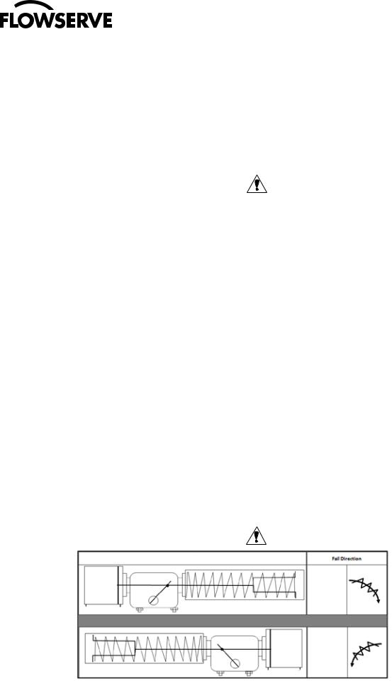
4.2Spring Module (see Fig.: 1)
CAUTION! Personal Injury may result if Step 2 is attempted before Step I is completed.
Actuator Configuration
CW
4 2
CWW
4 2
Fig.: 1 Spring Module
4
 Loading...