


 Loading...
Byron Jackson Type M
Double Mechanical Seal
Submersible Pumping Unit
USER INSTRUCTIONS:
INSTALLATION, OPERATION, MAINTENANCE
PCN=85392711 1042.293/9 • Edition June 2004

® |
Byron Jackson Double Mechanical Seal Submersible Pumping Unit • 1042.293/9 • June 04 |
|
CONTENTS
PAGE
1 INTRODUCTION AND SAFETY ................... |
5 |
1.1About the product and these user
|
instructions........................................... |
5 |
|
1.2 |
CE marking and approvals .................. |
5 |
|
1.3 |
Disclaimer ............................................ |
5 |
|
1.4 |
Copyright ............................................. |
6 |
|
1.5 |
Duty conditions .................................... |
6 |
|
1.6 |
Safety |
................................................... |
6 |
|
1.6.1 |
Safety symbols................................ |
6 |
|
1.6.2 |
General safety instructions.............. |
7 |
|
1.6.3 |
Personnel qualification, training |
|
|
|
and protective clothing .................... |
7 |
|
1.6.4 Authorized and prohibited use......... |
7 |
|
2 TRANSPORT AND STORAGE..................... |
9 |
||
3.5 |
Electrical requirements....................... |
17 |
|
|
3.5.1 |
General electrical requirements .... |
17 |
|
3.5.2 |
Motor protection ............................ |
18 |
|
3.5.3 |
Short circuit protection .................. |
18 |
4 INSTALLATION AND |
|
||
UNINSTALLATION ..................................... |
19 |
||
4.1 |
Fitter |
................................................... |
19 |
4.2 |
Equipment ....and personnel required |
19 |
|
|
4.2.1 Equipment and tools supplied |
|
|
|
..................................... |
with motor |
19 |
|
4.2.2 Equipment and tools to be |
|
|
|
..................... |
supplied by operator |
19 |
|
4.2.3 ........................ |
Personnel required |
21 |
4.3 |
Hydraulic ..........................connection |
21 |
|
4.4 |
Installation .......................................... |
23 |
|
|
4.4.1 ......................... |
Safety instructions |
23 |
|
4.4.2 ................ |
Sequence of installation |
23 |
|
4.4.3 ................. |
Prepare installation site |
23 |
|
4.4.4 |
Arrange components for |
|
|
..................................... |
installation |
24 |
|
2.1 |
Consignment receipt and |
|
4.4.5 |
Inspect components ...................... |
25 |
|
|
|
unpacking ............................................ |
9 |
4.4.6 |
Install motor .................................. |
26 |
|
|
2.2 |
Transport ........................................... |
10 |
4.4.7 |
Install coupling .............................. |
27 |
|
|
|
2.2.1 |
Safety instructions......................... |
10 |
4.4.8 |
Install pump bowl assembly .......... |
30 |
|
|
2.2.2 |
Equipment and personnel |
|
4.4.9 |
Install impeller ............................... |
32 |
|
|
|
required ........................................ |
10 |
4.4.10 |
Vent motor..................................... |
33 |
|
|
2.2.3 Transport of the motor................... |
10 |
4.4.11 |
Install power cable ........................ |
35 |
|
|
|
2.2.4 Transport of the pump bowl |
|
4.4.12 Fasten the power cable to the |
|
||
|
|
|
assembly ....................................... |
11 |
|
cable guard ................................... |
39 |
|
2.3 |
Storage and shipping......................... |
12 |
4.4.13 Install riser pipe, fasten power |
40 |
||
|
2.4 |
Recycling and end of product life |
13 |
|
cable to riser pipe.......................... |
||
|
4.4.14 Connect power cable to |
|
|||||
3 |
DESCRIPTION |
14 |
|
terminal box .................................. |
43 |
||
4.4.15 Connect terminal box to main |
|
||||||
|
3.1 |
Configurations.................................... |
14 |
|
power supply................................. |
43 |
|
|
|
3.1.1 |
General Description....................... |
14 |
4.5 Uninstallation...................................... |
45 |
|
|
|
3.1.2 |
Main Components ......................... |
14 |
4.5.1 |
Safety instructions......................... |
45 |
|
|
3.1.3 |
Motor serial number ...................... |
14 |
4.5.2 |
Uninstallation ................................ |
45 |
3.2 |
Design of major parts......................... |
14 |
|
3.3 |
Performance and operating limits...... |
15 |
|
|
3.3.1 |
Normal operating conditions.......... |
15 |
|
3.3.2 |
Design changes ............................ |
15 |
3.4Preconditions at the installation
site ..................................................... |
|
16 |
3.4.1 |
Survey of well................................ |
16 |
3.4.2 |
Crooked well ................................. |
16 |
3.4.3 Development of the well ................ |
16 |
|
3.4.4 |
Suction and submergence |
|
|
requirements ................................. |
16 |
3.4.5 Effect of pumping sand.................. |
16 |
|
3.4.6 Effect of air or gas ......................... |
16 |
|
3.4.7 Oxidizing and corrosive effects |
|
|
|
of chemicals, air and gases........... |
16 |
5 COMMISSIONING STARTUP, |
|
||
OPERATION AND SHUTDOWN ................ |
46 |
||
5.1 |
Safety instructions.............................. |
46 |
|
5.2 |
Direction of rotation ............................ |
46 |
|
5.3 |
Starting the pump ............................... |
46 |
|
|
5.3.1 First-time start-up of the pump ...... |
46 |
|
|
5.3.2 Normal start-up of the pump ......... |
47 |
|
5.4 |
Running or operation.......................... |
47 |
|
|
5.4.1 |
Performance and operating |
|
|
|
limits ........................................ |
47 |
|
5.4.2 |
Motor operation............................. |
48 |
|
5.4.3 |
Starting frequency ......................... |
48 |
5.5 |
Stopping and shutdown...................... |
49 |
|
Page 3 of 68

® |
Byron Jackson Double Mechanical Seal Submersible Pumping Unit • 1042.293/9 • June 04 |
|
6 MAINTENANCE .......................................... |
50 |
|
6.1 |
Safety instructions ............................. |
50 |
6.2 |
Maintenance schedule....................... |
50 |
6.3Working substances and auxiliary
|
|
agents ................................................ |
51 |
|
|
6.4 |
Motor maintenance............................ |
51 |
|
|
6.5 |
Pump maintenance............................ |
51 |
|
|
6.6 |
Pump test run .................................... |
51 |
|
|
6.7 |
Periodic testing of motor and pump... |
52 |
|
|
6.8 |
Electrical tests of the motor ............... |
53 |
|
|
|
6.8.1 |
Insulation test ................................ |
53 |
|
|
6.8.2 |
Continuity testing ........................... |
53 |
|
6.9 |
Spare parts ........................................ |
54 |
|
|
|
6.9.1 |
Recommended spares and |
|
|
|
|
consumable items ......................... |
54 |
|
|
6.9.2 |
Ordering spare parts ..................... |
54 |
|
|
6.9.3 Storage of spare parts ................... |
54 |
|
|
6.10 |
Tools for repair and maintenance...... |
55 |
|
7 |
FAULTS, CAUSES AND REMEDIES ......... |
56 |
||
8 |
PARTS LIST AND DRAWINGS .................. |
59 |
||
9 |
CERTIFICATION ......................................... |
60 |
||
10 |
OTHER RELEVANT DOCUMENTATION |
|
||
|
AND MANUALS .......................................... |
61 |
||
|
10.1 |
Change notes .................................... |
61 |
|
|
10.2 |
Abbreviations ..................................... |
61 |
|
11 |
GLOBAL CONTACT POINTS, EU CE |
|
||
|
MARKER AND SERVICE CONTACTS ...... |
62 |
||
12 |
APPENDIX |
................................................... |
63 |
|
|
12.1 |
Scope ...............................of delivery |
64 |
|
|
12.2 |
Data .........................................sheet |
65 |
|
|
12.3 |
Tightening .............................torques |
66 |
|
|
12.4 |
Safety ...........data sheet for motor oil |
67 |
|
Page 4 of 68

® |
Byron Jackson Double Mechanical Seal Submersible Pumping Unit • 1042.293/9 • June 04 |
|
1 INTRODUCTION AND SAFETY
1.1About the product and these user instructions
NOTE |
These user instructions must always |
|
be kept close to the product's operat- |
|
ing location of operation or directly |
|
with the product so that they are |
|
available to the operating personnel at |
|
any time. |
Flowserve's products are designed, developed and manufactured with state-of-the-art technologies in modern facilities. The pumping unit is produced with great care and commitment to continuous quality control, utilizing sophisticated quality techniques, and safety requirements.
Flowserve is committed to continuous quality improvement and being at service for any further information about the product in its installation and operation or about its support products, repair and diagnostic services.
These instructions are intended to facilitate familiarization with the product and its permitted use. Operating the product in compliance with these instructions is important to help ensure reliability in service and avoid risks. The instructions may not take into account local regulations; ensure such regulations are observed by all, including those installing the product. Always coordinate repair activity with operations personnel, and follow all plant safety requirements and applicable safety and health laws/regulations.
NOTE |
These instructions should be read |
|
prior to installing, operating, using |
|
and maintaining the equipment in |
|
any region worldwide. |
|
The equipment must not be put into |
|
service until all the conditions relat- |
|
ing to safety, noted in the instruc- |
|
tions, have been met. |
These user instructions outline the general procedures that must be observed to ensure long, trouble free performance of the pumping unit. However, it is assumed that plant personnel are familiar with the basic principles and tools involved in the installation, operation and maintenance of a pumping unit. Successful pumping unit operation is dependent on careful study of these user instructions
and a well planned and observed maintenance program.
In these user instructions, the numbers in brackets are item numbers, e. g.: shaft button screw (806-2). Refer to the drawings in Chapter 8 "Parts list and drawings", Page 59, for the position of the respective item.
1.2CE marking and approvals
It is a legal requirement that machinery and equipment put into service within certain regions of the world shall conform with the applicable CE Marking Directives covering Machinery and, where applicable, Low Voltage Equipment, Electromagnetic Compatibility (EMC) and Pressure Equipment Directive (PED).
Where applicable, the Directives and any additional Approvals cover important safety aspects relating to machinery and equipment and the satisfactory provision of technical documents and safety instructions. Where applicable, this document incorporates information relevant to these Directives and Approvals.
To check if the approvals apply and if the product itself is CE marked, check the serial number plate markings and the Certification, see Section 9 "Certification", Page 60.
1.3Disclaimer
Information in these user instructions is believed to be reliable. In spite of all the efforts of Flowserve Pump Division to provide sound and all necessary information the content of these user instructions may appear insufficient and is not guaranteed by Flowserve as to its completeness or accuracy.
Flowserve manufactures products according to International Quality Management System Standards as certified and audited by external Quality Assurance organizations. Genuine parts and accessories have been designed, tested and incorporated into the products to help ensure continued product quality and performance in use.
As Flowserve cannot test parts and accessories sourced from other vendors the incorrect installation of such parts and accessories may adversely affect the performance and safety features of the products. The failure to properly select, install or use authorized Flowserve parts and accessories is considered to be misuse. Damage or failure caused by misuse is not covered by Flowserve's warranty. In addition, any modification of
Page 5 of 68

® |
Byron Jackson Double Mechanical Seal Submersible Pumping Unit • 1042.293/9 • June 04 |
|
Flowserve products or removal of original components may impair the safety of these products in their use.
1.4Copyright
All rights reserved. No part of these user instructions may be reproduced, stored in a retrieval system or transmitted in any form or by any means without prior permission of Flowserve Pump Division.
1.5Duty conditions
This product has been selected to meet the specifications of your purchaser order. The acknowledgement of these conditions has been sent separately to the purchaser. A copy should be kept with these user instructions.
NOTE |
The product must not be operated |
|
beyond the parameters specified for |
|
the application. |
|
If there is any doubt as to the suit- |
|
ability of the product for the applica- |
|
tion intended, contact Flowserve for |
|
advice, quoting the serial number. |
If the conditions of service on your purchase order are changed (for example liquid pumped, temperature or duty) it is requested that the user seeks our written agreement before start up.
1.6Safety
1.6.1Safety symbols
These user instructions contain specific safety symbols where non-observance of an instruction would cause hazards.
Safety symbol and safety Meaning word
DANGER This symbol indicates an imminent hazardous situation.
The situation, if not avoided, will result in death or serious injury.
This symbol indicates a potentially hazardous situation.
The situation, if not avoided, could result in death or serious injury.
CAUTION This symbol indicates a potentially hazardous situation.
The situation, if not avoided, could result in minor or moderate injury.
CAUTION This word indicates a situation which, if not avoided, could damage the equipment.
NOTE This sign is not a safety symbol but indicates an important instruction in the assembly process.
The following symbols may be added to the above symbols
This symbol indicates a potentially hazardous situation due to hazardous and toxic fluid.
The situation, if not avoided, could result in death or serious injury.
This symbol indicates a potentially hazardous situation due to strong magnetic field.
The situation, if not avoided, could result in death or serious injury to persons with pacemaker implant.
Further, the situation could damage instruments and stored data sensitive to magnetic fields.
This symbol indicates a potentially hazardous situation in an explosive atmosphere according to ATEX.
The situation, if not avoided in the hazardous area, could cause an explosion.
Table 1 Safety symbols in these user instructions
Page 6 of 68
® |
Byron Jackson Double Mechanical Seal Submersible Pumping Unit • 1042.293/9 • June 04 |
|
1.6.2General safety instructions
NOTE |
Always follow |
|
|
• |
legal regulations |
|
• |
plant regulations |
|
• |
these user instructions |
|
concerning safety. |
|
Absolutely heed all information placed directly on the pumping unit and given in Chapter 12.2 "Data sheet", as for example
•rotation arrow
•labeling of connections
•rating plate.
Danger of injury by
•knocking against parts, tools or equipment
•jamming fingers or hands in or between parts, tools or equipment
•dropping parts, tools or equipment on parts of the body.
1.6.3Personnel qualification, training and protective clothing
Personnel qualification and training
All personnel involved in the operation, installation, inspection and maintenance of the pumping unit must be qualified and authorized to carry out the work involved.
If the personnel in question do not already possess the necessary knowledge and skill, appropriate training and instruction must be provided. If required, the operator may commission the manufacturer / supplier to provide applicable training.
Always co-ordinate repair activity with operations and health and safety personnel, and follow all plant safety requirements and applicable safety and health laws and regulations.
DANGER
All work on the electrical system may only be performed by qualified electricians!
All work on the hydraulic connections may only be performed by qualified fitters.
Protective clothing
During transport, installation and removal of the pumping unit, all personnel must wear
•helmet
•safety boots
•protective gloves
During operation of the pumping unit at the control center, all personnel must wear
•protective gloves
NOTE |
Also follow |
•legal regulations
•plant regulations concerning protective clothing.
1.6.4Authorized and prohibited use
The safe operation of the pumping unit can only be guaranteed if it is operated as authorized.
The only authorized utilization of the pumping unit is to pump water from a well. The pumping unit is to be operated submerged in water.
NOTE Not all components or subassemblies of a pumping unit are necessarily supplied by Flowserve or part of this delivery.
These user instructions apply only to the components or subassemblies supplied by Flowserve in this delivery, see Chapter 12.1 "Scope of delivery".
By not heeding this user instructions, product liability is rendered void.
Page 7 of 68

® |
Byron Jackson Double Mechanical Seal Submersible Pumping Unit • 1042.293/9 • June 04 |
|
Non-authorized utilization of the pumping unit includes:
•operating the pumping unit in a known malfunctioning state
•operating the pumping unit in conditions other than those given in Chapter 3.3.1 "Normal operating conditions", Page 15.
•making modifications of the pumping unit that are not authorized by Flowserve
•using spare parts that are not authorized by Flowserve.
CAUTION Alterations to the pumping unit are only permitted after written permission by Flowserve.
Only use spare parts that have been authorized by Flowserve.
Flowserve is not liable for any damage caused by the use of parts obtained from third parties.
Page 8 of 68

® |
Byron Jackson Double Mechanical Seal Submersible Pumping Unit • 1042.293/9 • June 04 |
|
2 TRANSPORT AND STORAGE
2.1Consignment receipt and unpacking
A submersible pumping unit consists of
•Motor
•Pump bowl assembly
•Non-return valve
•Power cable
•Riser pipe (discharge column)
•Cable or bracket to fasten the motor power cable onto the riser pipe
•Wellhead (surface plate)
•Terminal box or junction box
•Tools for installation and maintenance.
NOTE Not all components or subassemblies of a pumping unit are necessarily supplied by Flowserve or part of this delivery.
These user instructions apply only to the components or subassemblies supplied by Flowserve in this delivery, see Chapter 12 "Scope of delivery".
Flowserve generally ships the pumping unit in two packages:
•Main components described in Chapter 3.1.2 "Main Components", Page 14.
•Tools described in Chapter 4.4.4 ”Arrange components for installation", Page 24.
All components and parts are suitably protective wrapped, crated or mounted on skids as appropriate.
The motor is shipped nearly completely filled with oil, with an oil expansion bag (shipping bladder) mounted outside of the motor to allow thermal expansion and contraction of the motor oil.
The power cable, if included in the delivery, is shipped on a reel with a shipping cap or other protective covering installed to protect the connectors.
Immediately after receipt of the equipment
1.Uncrate all parts.
Check all crates, boxes and wrappings for any accessories or spare parts which may be packed separately with the equipment or attached to side walls of the box or equipment.
2.Check the scope of delivery.
•Check the delivery against the delivery and shipping documents for its completeness.
Each product has a unique serial number. Check that this number corresponds with that advised.
NOTE |
Make sure |
you |
can always quote |
|
each part's serial number in corre- |
||
|
spondence |
and |
when ordering |
|
spare parts or further accessories. |
||
•Inspect the delivery for transportation damage.
Immediately report any shortage and or damage to Flowserve and the shipping company.
Claims must be reported in writing within one month of receipt of the equipment. Flowserve does not accept latter claims.
3.Check the available power against the requirements given on the motor data plate and in Chapter 12.2 "Data sheet".
If the equipment is to be stored
•continue with Chapter 2.3 "Storage and ship- ping", Page 12.
If the equipment is to be installed
• continue with Chapter 4.4 "Installation", Page 23.
Page 9 of 68
® |
Byron Jackson Double Mechanical Seal Submersible Pumping Unit • 1042.293/9 • June 04 |
|
2.2Transport
2.2.1Safety instructions
Transport is the process of moving the pumping unit or its components from the installation site to a storage site, maintenance site or repair site, or vice versa.
During transport, always
•Work carefully to avoid accidents.
•Handle equipment carefully.
•Be sure lifting devices are in good condition and are capable of safely handling the weights to be lifted.
•Mark and seal off the transport route so that unauthorized personnel do not enter the danger area.
•Take precautions to prevent foreign materials or dirt from entering the working parts of pump and motor.
Take care that the hoist has an adequate carrying force. For weight see Chapter 12.2 "Data sheet".
Never step under floating load.
Watch for and avoid overhead obstructions including power lines.
2.2.2Equipment and personnel required
Provide the following equipment for the transport:
•Portable crane with adequate carrying force. For weight see Chapter 12.2 "Data sheet.
•Also see Chapter 4.2 "Equipment and personnel required", Page 19.
Flowserve recommends that 2 persons plus 1 crane operator perform the transport.
2.2.3Transport of the motor
Do not raise or move the motor by the power cables!
CAUTION The motor is a dynamically balanced machine and should be handled accordingly.
Take precautions to prevent foreign materials or dirt from entering the working parts of the motor.
1.Refer to Figure 1.
Place hitching line under lifting lugs.
Figure 1 Hitching line under lifting lugs
Page 10 of 68
® |
Byron Jackson Double Mechanical Seal Submersible Pumping Unit • 1042.293/9 • June 04 |
|
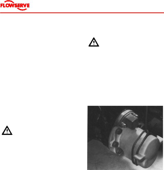
2.Refer to Figure 2.
Place a wire around the motor. The wire is to be positioned between stator and lower casing, approx. 1/3 from bottom of motor.
Figure 2 Lifting motor for installation
3.Lift the motor horizontally by 2 points.
4.Transport the motor horizontally to the installation or storage site.
5.Carefully lower the motor at the respective site and place it on the floor.
If the motor is to be stored:
•Continue with Chapter 2.3 "Storage and ship- ping", Page 12.
If the motor is to be installed in a well:
• Continue |
with Chapter 4 "Installation", |
Page 19. |
|
If the motor is to be maintained:
•Continue with Chapter 6 "Maintenance", Page 50.
2.2.4Transport of the pump bowl assembly
NOTE Not all components or subassemblies of a pumping unit are necessarily supplied by Flowserve or part of this delivery.
These user instructions apply only to the components or subassemblies supplied by Flowserve in this delivery, see Chapter 12.1 "Scope of delivery".
CAUTION Use care to prevent bumping, pushing, or scraping of pump bowl assembly parts, especially the shafts, or other machined surfaces.
Take precautions to prevent foreign materials or dirt from entering the working parts of the pump bowl assembly.
NOTE |
The following description refers to |
|
pumps without auxiliary carriers. |
|
Should the pump be delivered on an |
|
auxiliary carrier, refer to the pump |
|
manual for transportation instruc- |
|
tions. |
1.Connect the pump
•directly to the hoists, or
•to the cross-beam
of a portable crane.
2.By means of the crane, carefully lift the pump and move it to the desired site.
If the pump bowl assembly is to be stored:
•Continue with Chapter 2.3 "Storage and ship- ping", Page 12.
If the pump bowl assembly is to be installed in a well:
• Continue |
with Chapter 4 "Installation", |
Page 19. |
|
If the pump bowl assembly is to be maintained:
• Continue |
with Chapter 6 "Maintenance", |
Page 50. |
|
Page 11 of 68

® |
Byron Jackson Double Mechanical Seal Submersible Pumping Unit • 1042.293/9 • June 04 |
|
2.3Storage and shipping
For the removal of the pump from the well see Chapter 4.5 "Uninstallation", Page 45, if necessary.
Requirements for the storage area
•Safe
•Clean
•Away from extended periods of direct sunlight
•Well ventilated
•Dry
Air humidity: ................................40 % to 60 %
•Cool
Air temperature for motors
originally filled by Flowserve: ...+50 °C to -5 °C
CAUTION Always store motor and pump bowl assembly separately.
Prepare motor for storage or shipping after removing the motor from the well
1.Arrange the motor horizontally.
2.If pump and coupling are to be stored or shipped separately: Install coupling components on motor shaft.
3.Install power terminal shipping cap (112), power terminal gasket (744-6), and motor shipping caps (112-1).
4.If the motor is to be stored in a vertical position, proceed as follows:
a.Remove the adapter bracket (808).
b.Drill a vent hole in the motor shipping cap (112-1).
If the motor is returned to factory at a later time, seal the vent hole by a pipe plug.
5.If the motor is to be returned to the factory, proceed as follows:
a.Remove motor half-coupling (529) or motor one-piece coupling (531).
b.Lubricate shaft with some form of penetrating oil.
c.Place coupling and components in motor shipping cap (112-1) with its power terminal gasket (744-6) and bolt cap securely in place.
d.Elevate motor over a sump or drum to drain oil and water from motor.
e.Remove lower casing drain plug (806) from bottom of motor, then remove vent plugs (806-4 and 806-5) at top of motor and allow motor to fully drain.
f.Replace drain and vent plugs.
Prepare pump bowl assembly for storage or shipping
NOTE |
Not all |
components |
or sub- |
|
assemblies of a pumping unit are |
||
|
necessarily |
supplied by |
Flowserve |
|
or part of this delivery. |
|
|
|
These user instructions apply only |
||
|
to the components or sub- |
||
|
assemblies |
supplied by |
Flowserve |
|
in this delivery, see Chapter 12.1 |
||
|
"Scope of delivery". |
|
|
NOTE |
The following description refers to |
||
|
pumps without auxiliary carriers. |
||
Should the pump be delivered on an auxiliary carrier, refer to the pump manual for storage and shipping instructions.
1.Install blocks in the strainer to restrain the pump shaft.
This prevents shaft end float and possible internal damage during handling.
2.Make sure the bowl assembly is thoroughly dry.
3.Install suitable covers to seal off all openings.
Page 12 of 68

® |
Byron Jackson Double Mechanical Seal Submersible Pumping Unit • 1042.293/9 • June 04 |
|
Store pumping unit
NOTE |
The following description refers to |
|
pumps without auxiliary carriers. |
|
Should the pump be delivered on an |
|
auxiliary carrier, refer to the pump |
|
manual for storage and shipping |
|
instructions. |
Store the pumping unit as follows:
•Motor:
Preferably vertically Filled with oil
•Pump bowl assembly with rubber bearing bushes:
Vertically
•Pump bowl assembly with other than rubber bearing bushes:
Preferably vertically
DANGER
Horizontally stored motors and pump bowl assemblies must be secured against rolling.
Vertically stored motors and pump bowl assemblies must be secured by appropriate means in this storage position to prevent tipping over.
•Power cable:
Leads protected from moisture
NOTE |
Do not bend power cable during |
|
storage. |
Maintenance during storage
•Storage up to four weeks
At the beginning and end of the storage period: Carefully check the motor to be sure there are no signs of oil leakage.
•Storage between 1 and 24 months Maintenance of the motor, every 6 to 8 weeks:
1.Remove the motor shipping cap (112) at the motor.
2.Turn the motor shaft several times by means of a wrench.
3.Mount the motor shipping cap (112) to the motor.
Maintenance of the pump, every 6 to 8 weeks:
1.Remove the discharge housing and the non-return valve for the pump shaft.
2.Turn the pump shaft several times by means of a wrench.
4.Mount the discharge housing and non- return-valve to the pump.
•Storage for over 24 months
After a storage of more than 24 months, we recommend a complete visual inspection at our main factory or at your nearest Flowserve representative.
Shipping
Ship motor and pump bowl assembly
•in non-airtight protection film
•in wooden box or similar transport packaging.
2.4Recycling and end of product life
At the end of the service life of the pumping unit or its parts, the relevant materials and parts should be recycled or disposed of using an environmentally acceptable method and heeding local regulations.
If the product contains substances which are harmful to the environment, these should be removed and disposed of in accordance with local regulations. This also includes the liquids and or gases in the "seal system" or other utilities.
DANGER
Make sure that hazardous substances are disposed of safely and that the correct personal protective equipment is used.
The safety specifications must be in accordance with the local regulations at all times.
Hazardous substances in the pumping unit are
•Motor oil
Page 13 of 68

® |
Byron Jackson Double Mechanical Seal Submersible Pumping Unit • 1042.293/9 • June 04 |
|
3 DESCRIPTION
3.1Configurations
3.1.1General Description
The Flowserve submersible pumping unit is a combination of
•a vertical, oil filled motor with double mechanical seal
•a vertical pump bowl assembly
designed for sustained operation submerged in water. The motor is positioned directly below the pump bowl assembly.
The rotating element of the pump bowl assembly is driven from the bottom where its extended shaft is connected to the motor shaft by a coupling.
Power is supplied to the motor through a submarine power cable which is fastened to the riser pipe and extends to the starting equipment. Motor and pump bowl assembly are connected to the riser pipe. The riser pipe is threaded or flanged and coupled in random lengths and the entire unit is coupled to a wellhead assembly.
Each pumping unit has been individually manufactured according to the special requirements of the customer. The technical data is given in Chapter 12.2 "Data sheet".
3.1.2Main Components
A pumping unit consists of
•Motor
•Pump bowl assembly
•Non-return valve
•Power cable
•Riser pipe (discharge column)
•Cable or bracket to fasten the motor power cable onto the riser pipe
•Wellhead (surface plate)
•Terminal box or junction box
•Tools for installation and maintenance.
NOTE Not all components or subassemblies of a pumping unit are necessarily supplied by Flowserve or part of this delivery.
These user instructions apply only to the components or subassemblies supplied by Flowserve in this delivery, see Chapter 12.1 "Scope of delivery".
3.1.3Motor serial number
The motor serial number is on the name plate on the stator.
3.2Design of major parts
The motor is filled with, lubricated and cooled by a special mineral oil of high dielectric strength.
This oil
•allows high efficiency rotor-stator design,
•provides excellent insulation and lubrication qualities, and
•protects the motor from internal corrosion.
CAUTION The oil used in this pumping unit is specified in Chapter 12.2 "Data sheet".
Use of other oil
•may cause damage to the pumping unit
•renders Flowserve's warranty void.
The motor does not require periodic oil changes.
The oil is circulated within the motor by pumping action of the thrust bearing disc. Separation between the motor oil and pump liquid at the shaft exit is maintained by two mechanical seals.
The motor is pressure compensated.
The double mechanical seal system uses a pressure balance process to equalize the pressure differential across the seals, minimizing leakage and providing years of maintenance free service. The inner seal diverts any pumped fluid leakage via a communication line to a storage reservoir at the bottom of the motor. The motor is vented to the well by the balance line. As the oil expands, some oil is pushed out of the motor through the balance tube. As the oil cools down, pumped fluid is drawn back into the lower casing at the bottom of the motor through the balance tube.
Page 14 of 68

® |
Byron Jackson Double Mechanical Seal Submersible Pumping Unit • 1042.293/9 • June 04 |
|
3.3Performance and operating limits
3.3.1Normal operating conditions
Operating purpose
Submersible pumps serve to transport water under the operating conditions described in the following.
CAUTION Other uses, operating purposes or operating conditions must be agreed upon by Flowserve.
Water characteristics
•Water temperature: .............See Chapter 12.2
"Data sheet"
•Sand content: ......................Maximum 25 mg/l
Also see Chapter 3.4.3 "Development of the well", Page 16, and Chapter 3.4.5 "Effect of pumping sand", Page 16.
•No impurities which could lead to deposits and blockages within the pump or to deposits on the motor surface.
Also see Chapter 3.4.6 "Effect of air or gas", Page 16 and Chapter 3.4.7 "Oxidizing and corrosive effects of chemicals, air and gases", Page 16.
•No occurrence of water hammer
CAUTION At higher surrounding temperatures and/or lower flow velocities on the external motor surfaces, or if there is risk of clogging, special measures for heat dissipation are required.
Inform Flowserve of the surrounding conditions.
Flowserve will check the suitability of the pumping unit for its planned application and confirm its use, if applicable.
Pumping unit
•Correctly selected and adjusted motor protection
Operation
•Operation within prescribed voltage tolerance, see Chapter 12.2 "Data sheet"
•No operation against closed slide valve
•Permissible operational range: 50 % to 120 % of the optimal delivery rate
•Observation of the maximum permissible starting frequency
Installation position
Take the following criteria into account when determining the installation position and depth:
•Vertical installation in a well above the filter line, so that a perfect flow is guaranteed along the external motor wall.
•Sufficient water cover
•A static water level at least 2 m above the pump exit
•A dynamic water level above the suction housing, taking into account the required net positive suction head for the pump (see Chapter 12.2 "Data sheet")
•Flow rate (see Chapter 12.2 "Data sheet")
•Supply conditions of the pumping medium (dependent upon the installation conditions)
CAUTION The pumping unit should be installed above the well filter.
If this is not possible, prevent direct suction within the filter line by suitable measures (e.g. blind tube in the filter, outer pump mantle, pump with sand protection jacket.
3.3.2Design changes
Alternation or addition of the pumping unit may only take place
•by Flowserve, or
•after written consent by Flowserve.
Page 15 of 68

® |
Byron Jackson Double Mechanical Seal Submersible Pumping Unit • 1042.293/9 • June 04 |
|
3.4Preconditions at the installation site
3.4.1Survey of well
Always sound the well to make sure it is deep enough to permit installation of the pumping unit consisting of pump bowl assembly and motor. If the exact diameter and depth of the well casing is not known, "cage" the well following the procedure outlined in Chapter 3.4.2 "Crooked well", Page 16.
Experience indicates that many wells have more that one string of casing installed and frequently the lower sections are smaller in diameter than the surface casing. Be certain the submersible pumping unit will pass into the well freely and hang well above of the well bottom.
3.4.2Crooked well
A well that is known to be crooked and that has not previously accommodated a pumping unit of comparable size must be "caged" before the submersible pumping unit is installed.
1.Prepare a cage of the same length and diameter as the combined motor and pump bowl assembly, with 12 m to 15 m (40 feet to 50 feet) of the proper size of riser pipe.
2.Lower the cage into the well to the point at which the pumping unit is to be placed.
3.If the cage can be lowered to this point without touching the inner wall of the well, the submersible pumping unit can be installed.
3.4.3Development of the well
Do not use a new pumping unit to develop the well.
Developing, surging and freeing the well of sand are considered a part of the well drillers contract and should be accomplished by the use of a test pumping unit.
3.4.4Suction and submergence requirements
Pumping the well at a rate at which the pumping unit breaks suction will cause pump deterioration. It is suggested that a method be provided for keeping a record of the water level above the suction inlet.
The minimum submergence recommended is 3 m (10 feet) of riser pipe submergence below the
maximum well draw-down level, although some installations may require more submergence.
3.4.5Effect of pumping sand
Flowserve does not guarantee the pumping unit to be resistant against the erosive action of sand, silt or other abrasive materials suspended in water.
Pumping sand will adversely affect the motor because the vibration produced in a worn pump bowl assembly will be transmitted to the motor and could result in a shortened motor life.
3.4.6Effect of air or gas
The presence of gases in the water may reduce capacity and head of the pumping unit, thus decreasing the hydraulic performance. Further, air or gas in the water will cause deterioration of materials of the pumping unit sooner than under normal conditions.
3.4.7Oxidizing and corrosive effects of chemicals, air and gases
Even if the composition of the pumped water is known due to chemical analysis, it is not always possible to predict the corrosive action of water on the metals of the pumping unit.
In addition to chemicals, water may also contain entrained air or gases that have a definite oxidizing or corrosive action of their own. This action is accentuated by high velocities within the pump. Such conditions are not recognizable in the chemical analysis of the water.
Conforming with the Standards of the Hydraulic Institute of the United States and the practice of all reliable pump manufacturers, Flowserve does not guarantee its pumps and motors to be resistant against corrosive or electrolytic action.
Should you require motors or pumps to perform under oxidizing or corrosive conditions, contact Flowserve for further information.
Page 16 of 68

® |
Byron Jackson Double Mechanical Seal Submersible Pumping Unit • 1042.293/9 • June 04 |
|
3.5Electrical requirements
3.5.1General electrical requirements
The Byron Jackson submersible motor is designed for across-line start, eliminating the need for reduced voltage starting equipment. Maximum current inrush when the motor is connected across the line at full voltage will be limited to about 700 % of the rated load current.
Because starting the motor at full voltage results in high starting torque, the motor accelerates to operating speed very rapidly (within 0.8 seconds, typically), and current consumption correspondingly drops to normal. The rated power requirements of the motor are stated on the pump nameplate located on the wellhead.
Allowed combinations of voltage and frequency variations during operation are classified according IEC 60034 as being either Zone A or Zone B (Figure 3) or according NEMA (see Figure 4).
Figure 3 Voltage and frequency limits acc. IEC 60034
Voltage and frequency limits
|
|
|
|
|
0,1 |
|
|
|
|
|
|
|
|
|
|
|
|
0,08 |
|
|
|
|
|
|
|
|
|
|
|
|
0,06 |
|
|
|
|
|
|
|
|
|
|
|
|
0,04 |
|
|
|
|
|
|
|
p.u. |
|
|
|
|
0,02 |
|
|
|
|
|
|
|
Variation |
|
|
|
|
0 |
|
|
|
|
|
|
|
-0,05 |
-0,04 |
-0,03 |
-0,02 |
-0,01 |
0 |
0,01 |
0,02 |
0,03 |
0,04 |
0,05 |
||
Voltage |
||||||||||||
|
|
|
|
-0,02 |
|
|
|
|
|
|
||
|
|
|
|
|
|
|
|
|
|
|
||
|
|
|
|
|
-0,04 |
|
|
|
|
|
|
|
|
|
|
|
|
-0,06 |
|
|
|
|
|
|
|
|
|
|
|
|
-0,08 |
|
|
|
|
|
|
|
|
|
|
|
|
-0,1 |
|
|
|
|
|
|
Frequency Variation p.u.
Figure 4 Voltage and frequency limits acc. NEMA
The motor is capable of performing its rated torque continuously within Zone A, but need not comply fully with its performance at rated voltage and frequency (see rated point in Figure 3), and may exhibit some deviations. Temperature rises may be higher than at rated voltage and frequency. For conditions at the extreme boundaries of Zone A, the temperature rises and temperatures may exceed the specified limits of temperature rise and temperature by approximately 10 K.
Operation outside Zone A (within Zone B) may exhibit greater deviations from its performance at rated voltage and frequency than in Zone A. Temperature rises may be higher than at rated voltage and frequency and most likely will be higher than those in Zone A. Extended operation at the perimeter of Zone B is not recommended.
Low voltage is a serious problem since the operating motor current is increased, resulting in additional motor heating. However, the motor is designed to operate continuously at 110 % of rated current, so that some reduction in voltage can be tolerated as long as it is not also accompanied by an overload of the motor.
Page 17 of 68

® |
Byron Jackson Double Mechanical Seal Submersible Pumping Unit • 1042.293/9 • June 04 |
|
With variations in voltage, the motor characteristics will, in general, vary as given in Table 2.
Voltage |
110 % |
90 % |
|
|
|
Speed |
Increase 1 % |
Decrease 1.5 % |
|
|
|
Efficiency (full load) |
Increase 0.5 % |
Decrease 1 % |
|
|
|
Power factor (full load) |
Decrease 3 % |
No change |
|
|
|
Current (starting) |
Increase 11 % |
Decrease 11 % |
|
|
|
Current (full load) |
Decrease 8 % |
Increase 11 % |
|
|
|
Temperature |
Decrease 2 % |
Increase 5 % |
|
|
|
Table 2 Motor characteristics at varying voltage
Rated or full load current refers to the amperage drawn by the motor at nameplate output, frequency and voltage at the motor terminals. The maximum allowable current (except momentarily at start-up) is 110 % of the rated value.
The voltage on all three phases should be evenly balanced as closely as can be read on the usually available commercial voltmeter, because the current unbalance will be in the order of 6 to 10 times the voltage unbalance. Running the motor with the unbalanced voltage will lead to increased temperature and decreased motor life time, and therefore must be avoided.
Poor voltage regulations of an engine-driven generator, if the power is derived from such a source, can be very disadvantageous to the motor. Thus, Flowserve assumes no responsibility for pumping units operated on such equipment unless agreed on in writing.
Also, because of the unpredictable characteristics and past experiences associated with the use of phase converters, Flowserve must void all guarantees for applications that incorporate these devices as a means of obtaining three phase power.
3.5.2Motor protection
To protect the motor against power overload, an inverse time-lag overload relay must be provided, sensitive to phase failure and which compensates for temperature.
The over current relay for the switchgear and the safety fuses can be adjusted or selected according to Chapter 12.2 "Data sheet".
The adjustment of the motor protection switch (thermally delayed over current relay) must be done according to the value given in Chapter 12.2 "Data sheet".
The value given in Chapter 12.2 "Data sheet", is a standard value for the operating point. If the actual operational current in the operating point of the pump bowl assembly lies under this given value, the switch must be adjusted lower so that there is effective protection and malfunctions can be indicated in time.
DANGER
Do not set the motor protection adjustment higher than the highest permissible value given in Chapter 12.2 "Data sheet".
Do not test the perfect functioning of a motor protection switch by intentional single-phasing.
3.5.3Short circuit protection
To prevent short circuiting of the power cable and the motor, safety measures must be taken according to local ordinances.
Guide values for the safety fuse sizes can be taken from Chapter 12.2 "Data sheet".
Page 18 of 68

® |
Byron Jackson Double Mechanical Seal Submersible Pumping Unit • 1042.293/9 • June 04 |
|
4INSTALLATION AND UNINSTALLATION
4.1Fitter
It is recommended that the services of Flowserve be employed for the installation and initial starting of a Byron Jackson pump.
Such service will ensure the purchaser that the equipment is properly installed, and will provide an excellent opportunity for the plant operator to receive special instructions relative to the pumping unit.
4.2Equipment and personnel required
4.2.1Equipment and tools supplied with motor
Equipment and tools supplied with motor and half coupling
•Hex socket wrench for shaft button screw (806-2)
•Hex socket wrench for coupling set screw (806-1)
•Hex socket wrench for vent plug (806-4)
•Hex socket wrench for vent plug (806-5)
•Aligning jig assembly, including the following parts:
-Shim, shaft adjusting (262-6)
-Shim, shaft adjusting (262-7)
-Button, thrust (130)
-Screw, thrust Button (806-2)
-Washer, coupling lock screw (690-4)
-Screw, coupling lock (806-3)
-Aligning jig (265)
-Coupling, driver (529)
-Key, coupling (676-1)
-Screw, set, coupling (806-1)
4.2.2Equipment and tools to be supplied by operator
Provide the following equipment and tools:
•Lifting Equipment.
Must be of sufficient strength and rigidity to lift the complete unit safely, see Table 3, Page 20, and of sufficient height to allow clearance between load hook and foundation. For weight see Chapter 12.2 "Data sheet".
•Two pairs of correctly sized pipe elevators
•One correctly sized column U-plate
•One correctly sized motor U-plate (see Figure 5, Page 21 and Table 4, Page 21)
•One 1.2 - 1.8 m (4 - 6 feet) section of column, threaded and coupled, to be attached to the top case and used for handling the pump bowl assembly.
Deduct this length from total column length specifications.
•Column
A supply of pipe, in random lengths, threaded and coupled, of correct size to handle the unit capacity and total weight and of adequate length to set the unit at the correct pumping level in the well. The threading is 8 threads per 25 mm (1 inch) and 19 mm (0.75 inch) taper per foot.
•One pair of cable reel stands, with axle
•One portable insulation resistance tester ("Megger"), 0 - 100 MΩ / 1000 Volts
•One clamp-on ammeter
•One volt/ohmmeter
•Components for water level indicating system
•Special banding tool ("Band-it") for cable bands
•A length of 1.27 cm (0.5 inch) hemp rope and a cable installation wheel. Diameter must be at least 14 times cable outer diameter.
•Ordinary hand tools (mechanical and electrical) used in this kind of work
•Two sets of chain tongs
•Rubber mat and insulated gloves for electrical work in damp conditions
Page 19 of 68
® |
Byron Jackson Double Mechanical Seal Submersible Pumping Unit • 1042.293/9 • June 04 |
|
•An adequate supply of approved thread compounds, as follows
-For installation of the short section of column pipe, next to top case or top case
flange, use only Loctite 277 (Red) & Primer T or equal.
-For remaining column pipe threads, use a pipe thread compound that is capable of lubricating and sealing.
Column
Size |
Weight per foot in kg (pounds) |
|||
|
Empty |
Full |
|
|
2-1/2 |
2.6 |
(5.8) |
3.6 |
(7.9) |
3 |
3.4 |
(7.6) |
4.9 |
(10.8) |
|
|
|
|
|
4 |
4.9 |
(10.9) |
7.4 |
(16.4) |
|
|
|
|
|
5 |
6.7 |
(14.8) |
10.7 |
(23.5) |
|
|
|
|
|
6 |
8.7 |
(19.2) |
14.4 |
(31.7) |
8 |
11.3 |
(25.0) |
21.4 |
(47.2) |
|
|
|
|
|
10 |
14.5 |
(32.0) |
30.2 |
(66.6) |
|
|
|
|
|
12 |
20.4 |
(45.0) |
42.6 |
(93.9) |
|
|
|
|
|
Bowl Slumps |
|
|
|
|
Size |
|
Weight in kg (pounds) |
|
|
|
1st Stage |
Additional Stage |
||
8MQ |
36 |
(80) |
7 |
(15) |
|
|
|
|
|
10MQ |
79 |
(175) |
17 |
(37) |
|
|
|
|
|
11MQ |
132 |
(290) |
32 |
(70) |
|
|
|
|
|
12MQ |
200 |
(440) |
57 |
(125) |
13MQ |
284 |
(625) |
79 |
(175) |
|
|
|
|
|
15MQ |
386 |
(850) |
120 |
(265) |
|
|
|
|
|
Cable |
|
|
|
|
Volts |
Size |
Weight per foot |
||
|
|
|
in kg (pounds) |
|
|
|
8 |
0.14 |
(0.30) |
|
|
|
|
|
|
|
4 |
0.35 |
(0.77) |
|
|
|
|
|
600 |
|
2 |
0.50 |
(1.10) |
|
300MCM |
2.00 |
(4.40) |
|
|
|
|
|
|
|
500MCM |
3.08 |
(6.80) |
|
|
|
|
|
|
|
6 |
|
0.41 |
(0.90) |
|
|
|
|
|
5000 |
2 |
|
0.54 |
(1.20) |
|
|
|
|
|
1/0 |
|
1.00 |
(2.20) |
|
|
|
|||
|
|
|
|
|
|
4/0 |
|
1.54 |
(3.40) |
Motors
Nominal motor |
Horsepower |
Weight |
||
size |
|
in kg (pounds) |
||
|
7-1/2 |
211 |
(465) |
|
|
|
|
|
|
|
10 |
211 |
(465) |
|
|
|
|
|
|
8" |
20 |
227 |
(500) |
|
|
25 |
249 |
(550) |
|
|
30 |
249 |
(550) |
|
|
|
|
|
|
|
40 |
431 |
(950) |
|
|
|
|
|
|
|
50 |
431 |
(950) |
|
10" |
60 |
458 |
(1 010) |
|
|
|
|
||
75 |
458 |
(1 010) |
||
|
||||
|
|
|
|
|
|
100 |
490 |
(1 080) |
|
|
|
|
|
|
|
125 |
553 |
(1 220) |
|
|
125 |
915 |
(2 018) |
|
|
|
|
|
|
12" |
150 |
953 |
(2 100) |
|
|
|
|
||
175 |
1 002 |
(2 210) |
||
|
||||
|
|
|
|
|
|
200 |
1 027 |
(2 265) |
|
|
125 |
1 170 |
(2 580) |
|
|
|
|
|
|
|
150 |
1 288 |
(2 840) |
|
|
|
|
|
|
14" |
200 |
1 424 |
(3 140) |
|
|
|
|
||
|
250 |
1 485 |
(3 273) |
|
|
300 |
1 485 |
(3 273) |
|
|
|
|
|
|
|
300 |
1 690 |
(3 725) |
|
|
|
|
|
|
|
350 |
1 860 |
(4 100) |
|
17" |
400 |
1 928 |
(4 250) |
|
|
|
|
||
450 |
1 996 |
(4 400) |
||
|
||||
|
|
|
|
|
|
500 |
1 996 |
(4 400) |
|
|
|
|
|
|
|
600 |
2 087 |
(4 600) |
|
|
600 |
1 950 |
(4 300) |
|
|
|
|
|
|
|
800 |
2 359 |
(5 200) |
|
21" |
|
|
|
|
1 000 |
2 767 |
(6 100) |
||
|
|
|
|
|
|
1 200 |
3 221 |
(7 100) |
|
|
1 500 |
3 720 |
(8 200) |
|
|
|
|
|
|
Table 3 Component weight chart for calculating foundation, derrick and hoist loads
Page 20 of 68
® |
Byron Jackson Double Mechanical Seal Submersible Pumping Unit • 1042.293/9 • June 04 |
|
Figure 5 Motor U-plate
Nominal |
|
|
Dimensions in |
cm |
|
|
|||
motor |
|
|
|
|
|
(inches) |
|
|
|
size |
|
|
|
|
|
|
|
|
|
|
A |
|
B |
|
C |
|
D |
|
E |
|
|
|
|
|
|||||
|
|
|
|
|
|
|
|
|
|
8" |
38.10 |
|
0.95 + |
|
25.40 |
|
25.40 |
14.61 + |
|
|
(15) |
|
0.32 |
|
(10) |
|
(10) |
0.32 |
|
|
|
|
(0.375 + |
|
|
|
|
(5.750 + |
|
|
|
|
0.125) |
|
|
|
|
0.125) |
|
|
|
|
|
|
|
|
|
|
|
10" |
40.64 |
|
0.95 + |
|
30.48 |
|
25.40 |
18.10 + |
|
|
(16) |
|
0.32 |
|
(12) |
|
(10) |
0.32 |
|
|
|
|
(0.375 + |
|
|
|
|
(7.125 + |
|
|
|
|
0.125) |
|
|
|
|
0.125) |
|
|
|
|
|
|
|
|
|
|
|
12" |
45.72 |
|
1.27 + |
|
35.56 |
|
25.40 |
19.05 + |
|
|
(18) |
|
0.32 |
|
(14) |
|
(10) |
0.32 |
|
|
|
|
(0.500 + |
|
|
|
|
(7.500 + |
|
|
|
|
0.125) |
|
|
|
|
0.125) |
|
|
|
|
|
|
|
|
|
|
|
14" |
50.80 |
|
1.27 + |
|
35.56 |
|
25.40 |
24.77 + |
|
|
(20) |
|
0.32 |
|
(14) |
|
(10) |
0.32 |
|
|
|
|
(0.500 + |
|
|
|
|
(9.750 + |
|
|
|
|
0.125) |
|
|
|
|
0.125) |
|
|
|
|
|
|
|
|
|
|
|
21" |
91.44 |
|
1.27 + |
|
73.66 |
|
53.34 |
42.57 + |
|
|
(36) |
|
0.32 |
|
(29) |
|
(21) |
0.32 |
|
|
|
|
(0.500 + |
|
|
|
|
(16.760 |
|
|
|
|
0.125) |
|
|
|
|
+ 0.125) |
|
|
|
|
|
|
|
|
|
|
|
Table 4 Motor U-plate chart
4.2.3Personnel required
Flowserve recommends that 2 persons plus 1 crane operator perform the installation or uninstallation procedure.
4.3Hydraulic connection
Exemplary construction of a water supply system is depicted in Figure 6, Page 22. As this shows a basic arrangement, the actual layout must be suited to local and technical conditions.
DANGER
All work on the hydraulic connection may only be done by qualified fitters.
Page 21 of 68
Loading...