


 Loading...
ESP2 Vertical Immersion Sump Pump
HOC3 Hydraulics
PCN=71569292 – 4-12 (E)
Original Instructions
USER INSTRUCTIONS
Installation
Operation
Maintenance
 These instructions must be read prior to installing, operating, using and maintaining this equipment.

ESP2 USER INSTRUCTIONS ENGLISH PCN-(71569292) 4-12
CONTENTS |
|
|
|
Page |
|
1 INTRODUCTION AND SAFETY ........................... |
3 |
|
1.1 |
General ........................................................... |
3 |
1.2 |
CE marking and approvals.............................. |
3 |
1.3 |
Disclaimer ....................................................... |
3 |
1.4 |
Copyright......................................................... |
3 |
1.5 |
Duty conditions................................................ |
3 |
1.6 |
Safety .............................................................. |
4 |
1.7 |
Name plate and safety labels.......................... |
7 |
1.8 |
Noise level....................................................... |
8 |
2 TRANSPORT AND STORAGE ............................. |
9 |
|
2.1 |
Consignment receipt and unpacking............... |
9 |
2.2 |
Handling .......................................................... |
9 |
2.3 |
Lifting............................................................... |
9 |
2.4 |
Storage.......................................................... |
10 |
2.5 |
Recycling and end of product life.................. |
10 |
3 DESCRIPTION .................................................... |
10 |
|
3.1 |
Configurations ............................................... |
10 |
3.2 |
Nomenclature................................................ |
11 |
3.3 |
Design of major parts.................................... |
11 |
3.4 |
Performance and operation limits ................. |
11 |
4 INSTALLATION ................................................... |
15 |
|
INSTALLATION AND START-UP CHECKLIST.... |
15 |
|
4.1 |
Location......................................................... |
16 |
4.2 |
Part assemblies............................................. |
16 |
4.3 |
Foundation .................................................... |
16 |
4.4 |
Pump Mounting............................................. |
16 |
4.5 |
Driver Mounting............................................. |
16 |
4.6 |
Piping ............................................................ |
17 |
4.7 |
Electrical connections ................................... |
19 |
4.8 |
Level controls ................................................ |
19 |
APEX SWITCH .................................................... |
26 |
|
4.9 |
Protection systems........................................ |
27 |
5 COMMISSIONING, STARTUP, OPERATION AND |
||
SHUTDOWN ...................................................... |
27 |
|
5.1 |
Pre-commissioning procedure ...................... |
27 |
5.2 |
Bearing Lubrication ....................................... |
29 |
5.3 |
Setting the Impeller Clearance...................... |
31 |
5.4 |
Direction of rotation....................................... |
32 |
5.5 |
Guarding ....................................................... |
32 |
5.6 |
Priming and auxiliary supplies....................... |
32 |
5.7 |
Starting the pump .......................................... |
32 |
5.8 |
Running or operation .................................... |
33 |
5.9 |
Stopping and shutdown................................. |
34 |
5.10 Hydraulic, mechanical and electrical duty... |
34 |
|
6 MAINTENANCE................................................... |
35 |
|
6.1 |
Maintenance schedule .................................. |
35 |
6.2 |
Spare parts.................................................... |
36 |
6.3 |
Recommended spares and consumable items |
|
|
....................................................................... |
36 |
6.4 |
Tools required................................................ |
37 |
6.5 |
Fastener torques........................................... |
38 |
|
6.6 |
Setting impeller clearance and impeller |
|
|
replacement .................................................. |
38 |
|
|
6.7 |
Disassembly ................................................. |
38 |
|
6.8 |
Examination of parts ..................................... |
40 |
|
6.9 Assembly of pump and seal.......................... |
42 |
|
7 |
FAULTS; CAUSES AND REMEDIES ................. |
45 |
|
8 |
PARTS LIST AND DRAWINGS .......................... |
47 |
|
|
General arrangement drawing............................. |
59 |
|
9 |
CERTIFICATION................................................. |
59 |
|
10 OTHER RELEVANT DOCUMENTATION AND |
|
||
|
MANUALS.......................................................... |
59 |
|
|
10.1 |
Supplementary User Instructions ............... |
59 |
|
10.2 |
Change notes ............................................. |
59 |
|
10.3 |
Additional sources of information................ |
59 |
Page 2 of 64

ESP2 USER INSTRUCTIONS ENGLISH PCN-(71569292) 4-12
1 INTRODUCTION AND SAFETY
1.1 General
 These instructions must always be kept close to the product's operating location or directly with the product.
Flowserve products are designed, developed and manufactured with state-of-the-art technologies in modern facilities. The unit is produced with great care and commitment to continuous quality control, utilizing sophisticated quality techniques, and safety requirements.
Flowserve is committed to continuous quality improvement and being at your service for any further information about the product in its installation and operation or about its support products, repair and diagnostic services.
These instructions are intended to facilitate familiarization with the product and its permitted use. Operating the product in compliance with these instructions is important to help ensure reliability in service and avoid risks. The instructions may not take into account local regulations; ensure such regulations are observed by all, including those installing the product. Always coordinate repair activity with operations personnel, and follow all plant safety requirements and applicable safety and health laws/regulations.
 These instructions must be read prior to installing, operating, using and maintaining the equipment in any region worldwide. The equipment must not be put into service until all the conditions relating to safety noted in the instructions, have been met.
1.2 CE marking and approvals
It is a legal requirement that machinery and equipment put into service within certain regions of the world shall conform with the applicable CE Marking Directives covering Machinery and, where applicable, Low Voltage Equipment, Electromagnetic Compatibility (EMC), Pressure Equipment Directive (PED) and Equipment for Potentially Explosive Atmospheres (ATEX).
Where applicable, the Directives and any additional Approvals, cover important safety aspects relating to machinery and equipment and the satisfactory provision of technical documents and safety instructions. Where applicable this document incorporates information relevant to these Directives and Approvals.
To confirm the Approvals applying and if the product is CE marked, check the serial number plate markings and the Certification. (See section 9, Certification.)
1.3 Disclaimer
Information in these User Instructions is believed to be reliable. In spite of all the efforts of Flowserve Pump Division to provide sound and all necessary information the content of this manual may appear insufficient and is not guaranteed by Flowserve as to its completeness or accuracy.
Flowserve manufactures products to exacting International Quality Management System Standards as certified and audited by external Quality Assurance organizations. Genuine parts and accessories have been designed, tested and incorporated into the products to help ensure their continued product quality and performance in use. As Flowserve cannot test parts and accessories sourced from other vendors the incorrect incorporation of such parts and accessories may adversely affect the performance and safety features of the products. The failure to properly select, install or use authorized Flowserve parts and accessories is considered to be misuse. Damage or failure caused by misuse is not covered by the Flowserve warranty. In addition, any modification of Flowserve products or removal of original components may impair the safety of these products in their use.
1.4 Copyright
All rights reserved. No part of these instructions may be reproduced, stored in a retrieval system or transmitted in any form or by any means without prior permission of Flowserve Pump Division.
1.5 Duty conditions
This product has been selected to meet the specifications of your purchaser order. The acknowledgement of these conditions has been sent separately to the Purchaser. A copy should be kept with these instructions.
 The product must not be operated beyond the parameters specified for the application. If there is any doubt as to the suitability of the product for the application intended, contact Flowserve for advice, quoting the serial number.
If the conditions of service on your purchase order are going to be changed (for example liquid pumped, temperature or duty) it is requested that the user seeks the written agreement of Flowserve before start up.
Page 3 of 64

ESP2 USER INSTRUCTIONS ENGLISH PCN-(71569292) 4-12
1.6 Safety
1.6.1 Summary of safety markings
These User Instructions contain specific safety markings where non-observance of an instruction would cause hazards. The specific safety markings are:
 This symbol indicates electrical safety instructions where non-compliance will involve a high risk to personal safety or the loss of life.
 This symbol indicates safety instructions where non-compliance would affect personal safety and could result in loss of life.
 This symbol indicates “hazardous and toxic fluid” safety instructions where non-compliance would affect personal safety and could result in loss of life.
 This symbol indicates safety instructions where non-compliance will involve some risk to safe operation and personal safety and would damage the equipment or property.
 This symbol indicates explosive atmosphere zone marking according to ATEX. It is used in safety instructions where non-compliance in the hazardous area would cause the risk of an explosion.
 This symbol is used in safety instructions to remind not to rub non-metallic surfaces with a dry cloth; ensure the cloth is damp. It is used in safety instructions where non-compliance in the hazardous area would cause the risk of an explosion.
 This sign is not a safety symbol but indicates an important instruction in the assembly process.
1.6.2 Personnel qualification and training
All personnel involved in the operation, installation, inspection and maintenance of the unit must be qualified to carry out the work involved. If the personnel in question do not already possess the necessary knowledge and skill, appropriate training and instruction must be provided. If required the operator may commission the manufacturer/supplier to provide applicable training.
Always coordinate repair activity with operations and health and safety personnel, and follow all plant safety requirements and applicable safety and health laws and regulations.
1.6.3 Safety action
This is a summary of conditions and actions to help prevent injury to personnel and damage to the environment and to equipment. For products used in potentially explosive atmospheres section 1.6.4 also applies.
 NEVER DO MAINTENANCE WORK WHEN THE UNIT IS CONNECTED TO POWER (Lock out.)
 DRAIN THE PUMP AND ISOLATE PIPEWORK BEFORE DISMANTLING THE PUMP
The appropriate safety precautions should be taken where the pumped liquids are hazardous.
 FLUOROELASTOMERS (When fitted.) When a pump has experienced temperatures over 250 ºC (482 ºF), partial decomposition of fluoroelastomers (example: Viton) will occur. In this condition these are extremely dangerous and skin contact must be avoided.
 HANDLING COMPONENTS
Many precision parts have sharp corners and the wearing of appropriate safety gloves and equipment is required when handling these components. To lift heavy pieces above 25 kg (55 lb) use a crane appropriate for the mass and in accordance with current local regulations.
 NEVER OPERATE THE PUMP WITHOUT THE COUPLING GUARD AND ALL OTHER SAFETY DEVICES CORRECTLY INSTALLED
 GUARDS MUST NOT BE REMOVED WHILE THE PUMP IS OPERATIONAL
 THERMAL SHOCK
Rapid changes in the temperature of the liquid within the pump can cause thermal shock, which can result in damage or breakage of components and should be avoided.
 NEVER APPLY HEAT TO REMOVE IMPELLER Trapped lubricant or vapor could cause an explosion.
 HOT (and cold) PARTS
If hot or freezing components or auxiliary heating equipment can present a danger to operators and persons entering the immediate area, action must be taken to avoid accidental contact (such as shielding).
Page 4 of 64

ESP2 USER INSTRUCTIONS ENGLISH PCN-(71569292) 4-12
If complete protection is not possible, the machine access must be limited to maintenance staff only with clear visual warnings and indicators to those entering the immediate area. Note: bearing housings must not be insulated and drive motors and bearings may be hot.
If the temperature is greater than 68 °C (175 °F) or below 5 °C (20 °F) in a restricted zone, or exceeds local regulations, action as above shall be taken.


 HAZARDOUS LIQUIDS
When the pump is handling hazardous liquids care must be taken to avoid exposure to the liquid by appropriate pump placement, limiting personnel access and by operator training. If the liquid is flammable and/or explosive, strict safety procedures must be applied.
Gland packing must not be used when pumping hazardous liquids.
 PREVENT EXCESSIVE EXTERNAL PIPE LOAD
Do not use pump as a support for piping. Do not mount expansion joints, unless allowed by Flowserve in writing, so that their force, due to internal pressure, acts on the pump flange.
 ENSURE CORRECT LUBRICATION (See section 5, Commissioning, startup, operation and shutdown.)
 NEVER EXCEED THE MAXIMUM DESIGN PRESSURE (MDP) AT THE TEMPERATURE SHOWN ON THE PUMP NAMEPLATE
See section 3 for pressure versus temperature ratings based on the material of construction.
 NEVER OPERATE THE PUMP WITH THE DISCHARGE VALVE CLOSED
(Unless otherwise instructed at a specific point in the User Instructions.)
(See section 5, Commissioning start-up, operation and shutdown.)
 NEVER RUN THE PUMP DRY OR WITHOUT PROPER PRIME (Casing flooded)
 NEVER OPERATE THE PUMP AT ZERO FLOW OR FOR EXTENDED PERIODS BELOW THE MINIMUM CONTINUOUS FLOW
 THE PUMP SHAFT MUST TURN CLOCKWISE WHEN VIEWED FROM THE MOTOR END
It is absolutely essential that the rotation of the motor be checked before installation of the coupling spacer and starting the pump. Incorrect rotation of the pump for even a short period can unscrew the impeller, which can cause significant damage.
1.6.4 Products used in potentially explosive atmospheres
 Measures are required to:
•Avoid excess temperature
•Prevent buildup of explosive mixtures
•Prevent the generation of sparks
•Prevent leakages
•Maintain the pump to avoid hazard
The following instructions for pumps and pump units when installed in potentially explosive atmospheres must be followed to help ensure explosion protection. Both electrical and non-electrical equipment must meet the requirements of European Directive 94/9/EC.
1.6.4.1 Scope of compliance
 Use equipment only in the zone for which it is appropriate. Always check that the driver, drive coupling assembly, seal and pump equipment are suitably rated and/or certified for the classification of the specific atmosphere in which they are to be installed.
Where Flowserve has supplied only the bare shaft pump, the Ex rating applies only to the pump. The party responsible for assembling the pump set shall select the coupling, driver, seal and any additional equipment, with the necessary CE Certificate/ Declaration of Conformity establishing it is suitable for the area in which it is to be installed.
The output from a variable frequency drive (VFD) can cause additional heating affects in the motor. On pump installations controlled by a VFD, the ATEX Certification for the motor must state that it covers the situation where electrical supply is from the VFD. This particular requirement still applies even if the VFD is in a safe area.
Page 5 of 64
ESP2 USER INSTRUCTIONS ENGLISH PCN-(71569292) 4-12
1.6.4.2 Marking
An example of ATEX equipment marking is shown below. The actual classification of the pump will be engraved on the nameplate.
 II 2 GD c IIC 135ºC (T4)
Equipment Group  I = Mining
II = Non-mining
Category
2 or M2 = High level protection
3 = normal level of protection
Gas and/or dust G = Gas
D= Dust
c = Constructional safety
(in accordance with En13463-5)
Gas Group (Equipment Category 2 only) IIA – Propane (Typical)
IIB – Ethylene (Typical)
IIC – Hydrogen (Typical)
Maximum surface temperature (Temperature Class) (see section 1.6.4.3)
1.6.4.3 Avoiding excessive surface temperatures
 ENSURE THE EQUIPMENT TEMPERATURE CLASS IS SUITABLE FOR THE HAZARD ZONE
Pump liquid temperature
Pumps have a temperature class as stated in the ATEX Ex rating on the nameplate. These are based on a maximum ambient temperature of 40 ºC (104 ºF); refer to Flowserve for higher ambient temperatures.
The surface temperature on the pump is influenced by the temperature of the liquid handled. The maximum permissible liquid temperature depends on the temperature class and must not exceed the values in the table applicable below. The temperature rise at the seals and bearings and due to the minimum permitted flow rate is taken into account in the temperatures stated.
Maximum permitted liquid temperature for pumps
Temperature |
Maximum |
Temperature limit of liquid |
|
surface |
handled (* depending on |
||
class to |
|||
temperature |
material and construction |
||
EN 13463-1 |
|||
permitted |
variant – check which is lower) |
||
|
|||
T6 |
85 °C (185 °F) |
Consult Flowserve |
|
T5 |
100 °C (212 °F) |
Consult Flowserve |
|
T4 |
135 °C (275 °F) |
115 °C (239 °F) * |
|
T3 |
200 °C (392 °F) |
180 °C (356 °F) * |
|
T2 |
300 °C (572 °F) |
275 °C (527 °F) * |
|
T1 |
450 °C (842 °F) |
400 °C (752 °F) * |
Maximum permitted liquid temperature for pumps with self-priming casing
Temperature |
Maximum |
Temperature limit of liquid |
|
surface |
handled (* depending on |
||
class to |
|||
temperature |
material and construction |
||
EN 13463-1 |
|||
permitted |
variant - check which is lower) |
||
|
|||
T6 |
85 °C (185 °F) |
Consult Flowserve |
|
T5 |
100 °C (212 °F) |
Consult Flowserve |
|
T4 |
135 °C (275 °F) |
110 °C (230 °F) * |
|
T3 |
200 °C (392 °F) |
175 °C (347 °F) * |
|
T2 |
300 °C (572 °F) |
270 °C (518 °F) * |
|
T1 |
450 °C (842 °F) |
350 °C (662 °F) * |
The responsibility for compliance with the specified maximum liquid temperature is with the plant operator.
Temperature classification “Tx” is used when the liquid temperature varies and the pump could be installed in different hazardous atmospheres. In this case the user is responsible for ensuring that the pump surface temperature does not exceed that permitted in the particular hazardous atmosphere.
Do not attempt to check the direction of rotation with the coupling element/pins fitted due to the risk of severe contact between rotating and stationary components.
Where there is any risk of the pump being run against a closed valve generating high liquid and casing external surface temperature, it is recommended that users fit an external surface temperature protection device.
Avoid mechanical, hydraulic or electrical overload by using motor overload trips, temperature monitor or a power monitor and perform routine vibration monitoring.
In dirty or dusty environments, regular checks must be made and dirt removed from areas around close clearances, bearing housings and motors.
1.6.4.4 Preventing the buildup of explosive mixtures
 ENSURE PUMP IS PROPERLY FILLED AND VENTED AND DOES NOT RUN DRY
Ensure that the pump and relevant suction and discharge piping is totally filled with liquid at all times during the pumps operation so that an explosive atmosphere is prevented. In addition, it is essential to make sure that seal chambers, auxiliary shaft seal systems and any heating and cooling systems are properly filled.
Page 6 of 64
ESP2 USER INSTRUCTIONS ENGLISH PCN-(71569292) 4-12
If the operation of the system can not avoid this condition it is recommended that you fit an appropriate dry run protection device (for example liquid detection or a power monitor).
To avoid potential hazards from fugitive emissions of vapor or gas to atmosphere, the surrounding area must be well ventilated.
1.6.4.5 Preventing sparks
 To prevent a potential hazard from mechanical contact, the coupling guard must be non-sparking for Category 2.
To avoid the potential hazard from random induced current generating a spark, the baseplate must be properly grounded.
 Avoid electrostatic charge. Do not rub nonmetallic surfaces with a dry cloth; ensure the cloth is damp.
The coupling must be selected to comply with 94/9/EC and correct alignment must be maintained.
Additional requirements for pumps on nonmetallic baseplates
When metallic components are fitted on a nonmetallic baseplate they must be individually earthed.
1.6.4.6 Preventing leakage
 Avoid entrapment of liquid in the pump and associated piping due to closing of suction and discharge valves, which could cause dangerous excessive pressures to occur if there is heat input to the liquid. This can occur if the pump is stationary or running.
Bursting of liquid containing parts due to freezing must be avoided by draining or protecting the pump and auxiliary systems.
Where there is the potential hazard of a loss of a seal barrier fluid or external flush, the fluid must be monitored. If leakage of liquid to atmosphere can result in a hazard, the installation of a liquid detection device is recommended.
1.6.4.7 Maintenance of the centrifugal pump to avoid a hazard
 CORRECT MAINTENANCE IS REQUIRED TO AVOID POTENTIAL HAZARDS WHICH GIVE A RISK OF EXPLOSION
The responsibility for compliance with maintenance instructions is with the plant operator.
To avoid potential explosion hazards during maintenance, the tools, cleaning and painting materials used must not give rise to sparking or adversely affect the ambient conditions. Where there is a risk from such tools or materials, maintenance must be conducted in a safe area.
It is recommended that a maintenance plan and schedule is adopted. (See section 6, Maintenance.)
1.7 Name plate and safety labels
1.7.1 Nameplate
For details of nameplate, see the Declaration of Conformity and section 3.
1.7.2 Safety labels
ESSENTIAL PROCEEDURES BEFORE STARTING:
INSTALL AND OPERATE EQUIPMENT IN ACCORDAND WITH THE INSTRUCTION MANUAL SUPPLIED SEPARATELY.
ENSURE GUARDS ARE SECURELY IN
PLACE.
ENSURE CORRECT DIRECTION OF
ROTATION.
ENSURE CORRECT DRIVER DIRECTION OR ROTATION WITH COUPLING ELEMENT / PINS REMOVED: OTHERWISE SERIOUS DAMAGE MAY RESULT.
VERIFIER LE SENS CORRECT DE ROTATION DU MOTEUR. POMPE DESACCOUPLEE / ENTRETOISE DEMONTEE. NE PAS SUIVRE CETTE RECOMMANDATION PEUT CONDUIRE A DE GRAVES DOMMAGES POUR LA POMPE
J218JZ250
ENSURE ALL EXTERNAL CONNECTIONS TO THE PUMP / SHAFT SEALING AND DRIVER ARE CONNECTED AND OPERATIONAL
FULLY PRIME UNIT AND SYSTEM.
DO NOT RUN UNIT DRY
FAILURE TO FOLLOW THESE PROCEEDURES MAY RESULT IN PERSONAL INJURY
AND/ OR EQUIPMENT DAMAGE
J218JZ250
KONTROLLE VORGESCHRIEBENER DREHRICHTUNG ! HIERZU KUPPLUNGSZWISCHENSTÜCK / KUPPLUNGSBOLZEN ENTFERNEN. ANDERENFALLS ERNSTHAFTE SCHÄDEN !
ZORG VOOR JUISTE ROTATIERICHTING VAN DRIJFAS WAARBIJ DE KOPPELELELMENTEN / PENNEN VERWIJDERD ZIJN: VERZUM KAN ERNSTIGE SCHADE TOT GEVOLG HABBEN.
CDC: 603 604 610 612 621 623 624
Page 7 of 64

ESP2 USER INSTRUCTIONS ENGLISH PCN-(71569292) 4-12
1.8 Noise level
When pump noise level exceeds 85 dB(A) attention must be given to prevailing Health and Safety Legislation, to limit the exposure of plant operating personnel to the noise. The usual approach is to control exposure time to the noise or to enclose the machine to reduce emitted sound. You may have already specified a limiting noise level when the equipment was ordered, however if no noise requirements were defined then machines above a certain power level will exceed 85 dB(A). In such situations consideration must be given to the fitting of an acoustic enclosure to meet local regulations.
Pump noise level is dependent on a number of factors - the type of motor fitted, the operating capacity, pipework design and acoustic characteristics of the building.
Typical sound pressure levels measured in dB, and A-weighted are shown in the table below. The figures are indicative only, they are subject to a +3 dB tolerance, and cannot be guaranteed.
The values are based on the noisiest non-geared electric motors that are likely to be encountered. They represent sound pressure levels at 1 m (3.3 ft) from the directly driven pump, for "free field over a reflecting plane". For estimating LwA sound power level (re 1 pW) add 14dBA to the sound pressure value.
If a pump unit only has been purchased, for fitting with your own driver, then the "pump only" noise levels from the table should be combined with the level for the driver obtained from the supplier.
If the motor is driven by an inverter it may show an increase in noise level at some speeds. Consult a Noise Specialist for the combined calculation.
For units driven by equipment other than
electric motors or units contained within enclosures, see the accompanying information sheets and manuals.
Typical sound pressure level, dBA, LpA at 1 m reference 20 μPa
Motor size |
3550 r/min |
2900 r/min |
1750 r/min |
1450 r/min |
|||||
and speed |
Pump and |
Pump |
Pump and |
Pump |
Pump and |
Pump |
Pump and |
Pump |
|
kW (hp) |
motor |
only |
motor |
only |
motor |
only |
motor |
only |
|
dBA |
dBA |
dBA |
dBA |
dBA |
dBA |
dBA |
dBA |
||
<0.55 (<0.75) |
71 |
66 |
64 |
62 |
64 |
62 |
63 |
62 |
|
0.75 (1) |
74 |
66 |
67 |
62 |
67 |
62 |
63 |
62 |
|
1.1 |
(1.5) |
74 |
68 |
67 |
64 |
67 |
64 |
65 |
64 |
1.5 (2) |
77 |
70 |
70 |
66 |
70 |
66 |
66 |
66 |
|
2.2 (3) |
78 |
72 |
71 |
68 |
71 |
68 |
68 |
68 |
|
3 |
(4) |
81 |
74 |
74 |
70 |
74 |
70 |
70 |
70 |
4 |
(5) |
82 |
75 |
75 |
71 |
75 |
71 |
71 |
71 |
5.5 |
(7.5) |
90 |
77 |
83 |
73 |
76 |
73 |
72 |
71 |
7.5 (10) |
90 |
78 |
83 |
74 |
77 |
74 |
73 |
72 |
|
11 (15) |
91 |
80 |
84 |
76 |
78 |
76 |
74 |
73 |
|
15 |
(20) |
92 |
83 |
85 |
79 |
80 |
79 |
76 |
75 |
18.5 (25) |
92 |
83 |
85 |
79 |
80 |
79 |
76 |
75 |
|
22 |
(30) |
92 |
83 |
85 |
79 |
81 |
79 |
77 |
75 |
30 |
(40) |
100 |
85 |
93 |
81 |
84 |
80 |
80 |
76 |
37 |
(50) |
100 |
86 |
93 |
82 |
84 |
80 |
80 |
76 |
45 |
(60) |
100 |
87 |
93 |
83 |
84 |
80 |
80 |
76 |
55 |
(75) |
100 |
88 |
95 |
84 |
86 |
81 |
82 |
77 |
75 (100) |
100 |
90 |
95 |
86 |
88 |
81 |
83 |
78 |
|
90 (120) |
100 |
90 |
95 |
86 |
90 |
81 |
85 |
78 |
|
110 (150) |
100 |
91 |
95 |
87 |
91 |
83 |
86 |
79 |
|
150 |
(200) |
101 |
92 |
96 |
88 |
91 |
83 |
86 |
79 |
200 |
(270) |
(1) |
(1) |
(1) |
(1) |
(1) |
83 |
(1) |
80 |
300 |
(400) |
- |
- |
- |
- |
(1) |
84 |
(1) |
81 |
(1) Motors in this range are generally job specific and noise levels should be calculated based on actual equipment installed. For 960 r/min reduce 1450 r/min values by 5 dBA.
Page 8 of 64

ESP2 USER INSTRUCTIONS ENGLISH PCN-(71569292) 4-12
2 TRANSPORT AND STORAGE
2.1 Consignment receipt and unpacking
Immediately after receipt of the equipment it must be checked against the delivery/shipping documents for its completeness and that there has been no damage in transportation. Any shortage and/or damage must be reported immediately to Flowserve Pump Division and must be received in writing within ten days of receipt of the equipment. Later claims cannot be accepted.
Check any crate, boxes or wrappings for any accessories or spare parts that may be packed separately with the equipment or attached to pallet, box, or equipment.
Each product has a unique serial number. Check that this number corresponds with the order. Always quote this number in correspondence as well as when ordering spare parts or further accessories.
2.2 Handling
Boxes, crates, pallets or cartons may be unloaded using fork lift vehicles or slings dependent on their size and construction. The unit should be stored in a level position with no strains applied.
2.3 Lifting
 Pumps and motors often have integral lifting lugs or eye bolts. These are intended for use in only lifting the individual piece of equipment.
 Do not use eye bolts or cast-in lifting lugs to lift pump, motor and baseplate assemblies.
 Care must be taken to lift components or assemblies above the center of gravity to prevent the unit from flipping. This is especially true with In-Line pumps.
 Carefully sling ESP pumps so that bearing lubrication lines (3840.1) will not be bent or damaged when lifting.
It is advisable to raise the pump into the vertical position before uncrating. If this isn't possible, pumps over eight feet long must be supported at more than one place when raising to the vertical position. Use a support strap around the bottom column (1341.2) and on the motor support (3160).
Pump Weights
ESP2 |
Base Pump |
Kg (lb) per 0.15m |
|
|
(6 in.) |
Pump Size |
Wt. Kg (lb) |
Extra Length |
|
|
|
Group 1 |
|
|
1.5x1x6 |
136 (300) |
3.6 (8) |
3x1.5x6 |
139 (305) |
3.6 (8) |
3x2x6K |
145 (320) |
4.1 (9) |
1.5x1x8 |
148 (325) |
3.6 (8) |
3x1.5x8 |
150 (330) |
3.6 (8) |
3x2x8 |
152 (335) |
4.1 (9) |
Group 2 |
|
|
3x1.5x8 |
182 (400) |
6.8 (15) |
3x2x8 |
184 (405) |
7.3 (16) |
4x3x8 |
223 (490) |
7.7 (17) |
4x3x8L |
223 (490) |
7.7 (17) |
2x1x10 |
182 (400) |
6.8 (15) |
3x1.5x10 |
223 (490) |
6.8 (15) |
3x2x10 |
232 (510) |
7.3 (16) |
4x3x10 |
286 (630) |
7.7 (17) |
4x3x10L |
309 (680) |
7.7 (17) |
6x4x10 |
323 (710) |
8.6 (19) |
3x1.5x13 |
259 (570) |
6.8 (15) |
3x2x13 |
264 (580) |
7.3 (16) |
4x3x13 |
302 (665) |
7.7 (17) |
Group 3 |
|
|
6x4x13 |
407 (895) |
11.4 (25) |
8x6x13 |
545 (1200) |
15 (33) |
10x8x13 |
616 (1355) |
16.4 (36) |
8x6x15 |
561 (1235) |
15 (33) |
10x8x15 |
645 (1420) |
16.4 (36) |
|
|
|
 Base pump lengths are 0.61m (2 ft.) for Group 1 & Group 2 pumps and 0.91m (3 ft.) for Group 3 pumps.
 On pumps equipped with grease lubricated shaft bearings, (3020.1 and 3020.2) take care not to flush the grease from the bearings.
Page 9 of 64

ESP2 USER INSTRUCTIONS ENGLISH PCN-(71569292) 4-12
2.4 Storage
 Store the pump in a clean, dry location away from vibration. Leave flange covers in place to keep dirt and other foreign material out of pump casing.
The pump may be stored as above for up to 6 months. Consult Flowserve for preservative actions when a longer storage period is needed.
2.4.1 Short term storage and packaging
Normal packaging is designed to protect the pump and parts during shipment and for dry, indoor storage for up to six months or less. The following is an overview of our normal packaging:
•All loose unmounted items are packaged in a water proof plastic bag or box.
•Inner surfaces of the bearing housing, shaft (area through bearing housing) and bearings are coated with Cortec VCI-329 rust inhibitor, or equal.
•Regreaseable bearings in the pump are packed with Keystone 81-EP-2 lithium-based grease for the thrust bearing (and the line shaft bearings when grease lubrication is used).
•The internal surfaces of ferrous casings, covers, flange faces, and the impeller surface are sprayed with Cortec VCI-389, or equal
•Exposed shafts are taped with Polywrap
•Flange covers are secured to both the suction and discharge flanges
•In some cases with assemblies ordered with external piping, components may be disassembled for shipment
•The pump must be stored in a covered, dry location
•Every three months the pump shaft should be rotated several revolutions to prevent brinelling of the thrust bearing and sticking of the seal faces (if fitted).
2.4.2 Long term storage and packaging
Long term storage is defined as more than six months, but less than 12 months. The procedure Flowserve follows for long term storage of pumps is given below. These procedures are in addition to the short term procedure.
•Each assembly is hermetically (heat) sealed from the atmosphere by means of tack wrap sheeting and rubber bushings (mounting holes)
•Desiccant bags are placed inside the tack wrapped packaging
•A solid wood box is used to cover the assembly
This packaging will provide protection for up to twelve months from humidity, salt laden air, dust etc.
After unpacking, protection will be the responsibility of the user. Addition of oil to the bearing housing will remove the inhibitor. If units are to be idle for extended periods after addition of lubricants, inhibitor oils and greases should be used.
2.5 Recycling and end of product life
At the end of the service life of the product or its parts, the relevant materials and parts should be recycled or disposed of using an environmentally acceptable method and in accordance with local regulations. If the product contains substances that are harmful to the environment, these should be removed and disposed of in accordance with current local regulations. This also includes the liquids and/or gases that may be used in the "seal system" or other utilities.

 Make sure that hazardous substances are disposed of safely and that the correct personal protective equipment is used. The safety specifications must be in accordance with the current local regulations at all times.
3 DESCRIPTION
3.1 Configurations
The ESP2 vertical immersion sump pumps are separately coupled, metallic construction, single stage, centrifugal pumps for wet pit applications.
The ESP2 wetted parts are available in a wide range of materials to handle most fluids. Vapor tight, vapor proof, and pressurized options are available.
Figure 3-1: Nameplate mounted to housing
Serial No.
Equipment No.
Purchase Order
Model ESP2
Size 6X4X10
MDP
Material
Date DD/MMM/YY
Page 10 of 64
ESP2 USER INSTRUCTIONS ENGLISH PCN-(71569292) 4-12
3.2 Nomenclature
The pump size will be engraved on the nameplate typically as below:
3.4 Performance and operation limits
This product has been selected to meet the specification of your purchase order. See section 1.5.
6 X 4 X 10
•“6” = nominal suction port size (in.)
•“4” = Nominal discharge port size (in.)
•Nominal maximum impeller diameter. “10” = 10 in.
•Actual impeller size
“9.5” = 9 ½ in. diameter; “8.13” = 8 ⅛ in; ”7.75” = 7 ¾ in
3.3 Design of major parts
3.3.1 Pump casing
Casings are either a single or double volute design with a centerline discharge.
3.3.2 Impeller
The impeller is an open design and is threaded to the end of the shaft.
3.3.3 Shaft
Solid shafting is supported on plain bearings with a thrust bearing located above the sump level.
3.3.4 Pump bearings and lubrication
Grease lubricated double row angular contact ball bearings are fitted as standard for the external thrust bearings. The plain bearings that support the shaft against radial loads can be lubricated either by external flush, product, or grease (see Fig. 3-4).
3.3.5 Bearing housing
The external bearing housing holds the thrust bearing and has lip seals to prevent ingress of contaminates to the bearing grease.
3.3.6 Shaft seal
There is no shaft seal required near the impeller since the pump is submerged. Only a small amount of pressurized fluid escapes through controlled leak paths from the backside of the impeller. Packing or a mechanical seal can be fitted above the sump level to provide vapor proof or pressurized options for the application.
3.3.7 Driver
The driver is normally a vertical electric motor.
3.3.8 Accessories
Accessories may be fitted when specified by the customer.
The following data is included as additional information to help with your installation. It is typical, and factors such as liquid being pumped, temperature, material of construction, and seal type may influence this data. If required, a definitive statement for your application can be obtained from Flowserve.
3.4.1 Minimum continuous flow
The minimum continuous flow (MCF) is based on a percentage of the best efficiency point (BEP). Figure 3-2 identifies the MCF for all ESP pump models.
FIGURE 3-2: Minimum continuous flow
Pump size |
|
MCF % of BEP |
|
3500/2900 |
1750/1450 |
1180/960 |
|
|
r/min |
r/min |
r/min |
Group 1 |
|
|
|
1.5x1x6 |
10 |
10 |
10 |
3x1.5x6 |
10 |
10 |
10 |
3x2x6K |
10 |
10 |
10 |
1.5x1x8 |
10 |
10 |
10 |
3x1.5x8 |
n.a. |
10 |
10 |
3x2x8 |
n.a. |
10 |
10 |
Group 2 |
|
|
|
3x1.5x8 |
10 |
10 |
10 |
3x2x8 |
10 |
10 |
10 |
4x3x8 |
25 |
10 |
10 |
4x3x8L |
n.a. |
25 |
10 |
2x1x10 |
n.a. |
25 |
10 |
3x1.5x10 |
n.a. |
25 |
10 |
3x2x10 |
n.a. |
25 |
10 |
4x3x10 |
n.a. |
25 |
10 |
4x3x10L |
n.a. |
25 |
10 |
6x4x10 |
n.a. |
25 |
10 |
3x1.5x13 |
n.a. |
25 |
10 |
3x2x13 |
n.a. |
25 |
10 |
4x3x13 |
n.a. |
25 |
10 |
Group 3 |
|
|
|
6x4x13 |
n.a. |
25 |
10 |
8x6x13 |
n.a. |
25 |
10 |
10x8x13 |
n.a. |
25 |
10 |
8x6x15 |
n.a. |
n.a. |
25 |
10x8x15 |
n.a. |
n.a. |
25 |
Page 11 of 64

ESP2 USER INSTRUCTIONS ENGLISH PCN-(71569292) 4-12
3.4.2 Minimum suction pipe submergence
The minimum submergence is shown in Figures 3- 3A and 3-3B below.
FIGURE 3-3A
Minimum submergence (meters)
Suct. |
|
|
|
|
|
|
|
|
Flow |
|
(m3/hr.) |
|
|
|
|
|
Size |
6.8 |
11.4 |
20.5 |
45.5 |
79.5 |
136 |
273 |
341 |
500 |
568 |
727 |
1023 |
1250 |
|||
1.5 in |
0.30 |
0.55 |
1.07 |
2.65 |
|
|
|
|
|
|
|
|
|
|
|
|
2 in |
|
0.30 |
0.58 |
1.40 |
2.74 |
|
|
|
|
|
|
|
|
|
|
|
3 in |
|
|
0.30 |
0.79 |
1.52 |
2.38 |
|
|
|
|
|
|
|
|
|
|
4 in |
|
|
|
0.30 |
0.55 |
1.07 |
2.13 |
|
|
|
|
|
|
|
||
6 in |
|
|
|
|
|
0.43 |
0.76 |
1.19 |
1.83 |
|
|
|
|
|||
8 in |
|
|
|
|
|
|
|
|
|
0.55 |
0.94 |
1.19 |
1.65 |
|
|
|
10 in |
|
|
|
|
|
|
|
|
|
|
|
|
0.64 |
0.85 |
1.22 |
1.52 |
FIGURE 3-3B |
|
|
|
|
|
|
|
|
|
|
|
|
|
|
|
|
Minimum submergence (feet) |
|
|
|
|
|
|
|
|
|
|
|
|
|
|||
Suct. |
|
|
|
|
|
|
|
|
Flow |
|
(GPM) |
|
|
|
|
|
Size |
30 |
50 |
90 |
200 |
350 |
|
600 |
|
1200 |
|
1500 |
2200 |
2500 |
3200 |
4500 |
5500 |
1.5 in |
1.0 |
1.8 |
3.5 |
8.7 |
|
|
|
|
|
|
|
|
|
|
|
|
2 in |
|
1.0 |
1.9 |
4.6 |
9.0 |
|
|
|
|
|
|
|
|
|
|
|
3 in |
|
|
1.0 |
2.6 |
5.0 |
|
7.8 |
|
|
|
|
|
|
|
|
|
4 in |
|
|
|
1.0 |
1.8 |
|
3.5 |
|
7.0 |
|
|
|
|
|
|
|
6 in |
|
|
|
|
|
|
1.4 |
|
2.5 |
|
3.9 |
6.0 |
|
|
|
|
8 in |
|
|
|
|
|
|
|
|
|
|
1.8 |
3.1 |
3.9 |
5.4 |
|
|
10 in |
|
|
|
|
|
|
|
|
|
|
|
|
2.1 |
2.8 |
4.0 |
5.0 |
Page 12 of 64

ESP2 USER INSTRUCTIONS ENGLISH PCN-(71569292) 4-12
3.4.3 ESP2 Bearing Materials
CARBON - Carbon graphite, especially developed for sump pump applications, is chemically inert. The self lubricating properties of graphite present in the carbon bearings enhances its dry running capabilities.
BRONZE - SAE 660 Bronze (grooved when grease lubricated).
CAST IRON - ASTM A48 Class 30 iron (grooved when grease lubricated).
RUBBER - Resilient compounded rubber, fluted to allow abrasives to wash away.
FIGURE 3-4: ESP2 Bearing selection
VITON - Resilient Viton, fluted to allow handling of dirty corrosive liquids not able to be handled by carbon or rubber.
TEFLON - Fiberglass & moly-disulphide-filled, with low cold flow, high tensile and elongation characteristics.
All bearing materials are enclosed in an AISI-316 shell (ex. Bronze & Cast Iron). Higher alloys are available (grooved when grease lubricated).
Bearing |
Max. Product |
Pumped Liquid |
Lubricant |
Shaft |
Material |
Temp. |
|
|
Material |
CARBON |
177°C |
Most clean acids, |
External Flush |
Steel or SS |
|
(350°F) |
genera! chemical, cold |
Product Lube |
Steel or SS |
|
|
or hot water, cleaning |
|
|
|
|
fluids, gasoline, |
|
|
|
|
kerosene, jet fuels |
|
|
|
|
|
|
|
BRONZE |
82°C |
Water and other |
External Flush |
Steel only |
|
180°F |
compatible liquids |
Product Lube |
Steel only |
|
|
|
Grease |
Steel only |
CAST IRON |
82°C |
Water and other |
External Flush |
Steel |
|
(180°F) |
compatible liquids |
Product Lube |
Steel |
|
|
including alkaline |
Grease |
Steel |
|
|
caustics |
|
|
RUBBER |
71°C |
General abrasive liquids |
External Flush |
SS only |
|
(160°F) |
compatible with rubber |
Product Lube |
SS only |
|
|
|
|
|
TEFLON |
177°C |
Clean acids not |
External Flush |
SS only |
|
(350°F) |
compatible with carbon |
Product Lube |
SS only |
|
Liquid Lube |
|
|
|
|
|
|
|
|
TEFLON |
82°C |
Clean acids not |
Grease |
SS only |
|
(180°F) |
compatible with carbon |
|
|
|
Grease Lube |
|
|
|
VITON |
149°C |
Dirty acids not |
External Flush |
SS only |
|
(300°F) |
compatible with carbon |
Product Lube |
SS only |
|
|
or rubber |
|
|
Page 13 of 64

ESP2 USER INSTRUCTIONS ENGLISH PCN-(71569292) 4-12
FIGURE 3-5: Engineering information
Page 14 of 64

ESP2 USER INSTRUCTIONS ENGLISH PCN-(71569292) 4-12
4 INSTALLATION
INSTALLATION AND START-UP CHECKLIST
1.Check that the sump design will keep the liquid level within the proper range.
2.Check that the pump location is accessible and has adequate ventilation.
3.Verify that the pump and motor are suitable for the pump environment.
4.Check the sump design to be sure it is adequate to support the complete pumping assembly,
5.Verify the discharge piping meets Hydraulic Institute Standards for design and is properly supported.
6.Install the suction strainer
7.Install the liquid level controls.
8.If pump was ordered for vapor proof or pressurized design, install sealing device.
9.Lift the pump into place, level and tighten the mounting plate bolts.
10.Install the motor on the pump, but do not connect the coupling or electric power.
11.Connect the wiring to the liquid level indicators and pump controls, as required.
12.Connect the discharge piping,
13.Check that all auxiliary piping is connected
14.Verify the pump is free of pipe strain by turning the shaft by hand.
15.Verify the impeller setting.
16.Lubricate the driver, pump thrust and lineshaft bearings as required using approved lubricants.
17.Connect the wiring for the motor.
18.Turn power ON and jog the driver to verify proper rotation; clockwise looking down.
19.Turn power OFF and assemble coupling and install coupling guard. Then turn power ON, but do not start the driver.
1 _________ |
__________ |
|
2 |
_________ |
__________ |
3 |
_________ |
__________ |
4 |
_________ |
__________ |
5 |
_________ |
__________ |
6 |
_________ |
__________ |
7 |
_________ |
__________ |
8 |
_________ |
__________ |
9 |
_________ |
__________ |
10 _________ |
__________ |
|
11 _________ |
__________ |
|
12 _________ |
__________ |
|
13 _________ |
__________ |
|
14 _________ |
__________ |
|
15 _________ |
__________ |
|
16 _________ |
__________ |
|
17 _________ |
__________ |
|
18 _________ |
__________ |
|
19 _________ |
__________ |
|
Page 15 of 64

ESP2 USER INSTRUCTIONS ENGLISH PCN-(71569292) 4-12
4.1 Location
The pump should be located to allow room for installation, access, ventilation, maintenance, and inspection with ample headroom for lifting. Refer to the general arrangement drawing for the pump set. If pump is furnished with external flush-lubricated bearings, the fluid lines must be accessible from the pump location.
Also important, especially in the larger flow units, is proper sump design. Liquid velocity approaching the pump should be one foot per second or less. When more than one pump is installed and used at the same time in the same sump, the location and spacing of the pumps are important. The guidelines for sump design and pump placement as outlined in the "Hydraulic Institute Standards" are recommended.
4.2 Part assemblies
•Pumps are shipped completely assembled except for driver, strainer (6531), float controls (if furnished), pit cover, and the mechanical seal (4200) or packing (4130) for the stuffing box on a vapor proof or pressurized design pump.
•When mechanical seals are furnished, they should be installed before the motor is put in place. Refer to seal installation instructions in section 5.1.
•Vapor Proof and Pressurized design pumps are furnished with an upper stuffing box (4100). If the stuffing box does not already have the packing (4130) or seal (4200) installed, then they should be installed before the motor is mounted. See section 5.1.
•The driver will be mounted after the pump is installed.
•When the pump is shipped, all threads and all openings are covered. This protection should not be removed until installation. If the pump is removed from service, this protection should be reinstalled.
4.3 Foundation
There should be adequate space for workers to install, operate, and maintain the pump. The foundation should be sufficient to absorb any vibration and should provide a rigid support for the pump and motor. Recommended mass of a concrete foundation should be three times that of the pump, motor and mounting plate. Supporting members must be sufficiently strong to prevent spring action and/or lateral movement.
4.4 Pump Mounting
The pump may be mounted directly on the pit using the pump mounting plate (6110) or in conjunction with a pit cover.
a)The pump was checked during assembly at the factory to make sure the pump shaft (2100) rotated freely by hand. Handling during shipment, storage, or preparation for installation could have caused distortions resulting in pump shaft binding. Check the shaft to make sure that it will rotate freely by hand.
b)Check all bolts and nuts for tightness, then carefully lower the assembled pump into the pit, taking care not to damage lube lines or float control equipment. Make sure that any equipment used to lift the pump or any of its components is capable of supporting the weights encountered. Make sure that all parts are properly rigged before attempting to lift.
c)Pump mounting plate and/or pit cover must maintain a tolerance of 2.5mm/m (0.03in/ft) level from one side of the plate to the other, and be supported evenly at all points before being bolted down.
d)If the sump doesn't provide a level mounting surface for the pump, drive wedges under the mounting plate/pit cover until pump levels out. The wedges must be able to support the weight of the entire pumping assembly and hold the assembly steady enough that no excess vibration occurs.
e)Do not bolt the discharge flange of the pump to the piping until the baseplate foundation is completely installed.
f)Run piping to the discharge of the pump. There should be no piping loads transmitted to the pump after connection is made.
4.5Driver Mounting
a)Before the motor is installed, be sure to connect the motor half coupling and the pump half coupling onto their respective shafts.
b)Carefully lift the motor and place it on the support head (3160) of the pump.
c)Turn the motor frame to one of the four positions where the motor bolt holes line up to the support head (3160). Select the position of the motor to suit the desired conduit box location. Install the motor hold down bolts (6570.1). In some instances a motor adapter may be furnished. In this case the adapter must be installed before the motor can be mounted.
Page 16 of 64
ESP2 USER INSTRUCTIONS ENGLISH PCN-(71569292) 4-12
d)Locate the coupling and source of electrical power but DO NOT ASSEMBLE THE COUPLING AT THIS TIME.
e)Connect the motor terminals to the leads from the starter panel. Make sure the motor shaft and/or coupling is not touching any part of the pump shaft or pump half coupling. Rotate the motor shaft by hand to make sure it is free to rotate when energized.
 Never check driver rotation unless the pump and driver are disconnected and physically separated. Failure to follow this instruction can result in serious damage to the pump and driver if rotation is in the wrong direction.
f)Jog the motor and check for proper rotation which should be clockwise when looking down on top of the motor. If rotation is wrong, interchange any two motor connections on three-phase motors. On single-phase motors, follow the motor manufacturer’s instructions. After changing the connections, again check the rotation to ensure that the direction is correct.
g)Disconnect and lockout the power supply to the driver.
h)The coupling can now be fully installed and join the driver and pump shafts together (see section 5.4.2).
i)Install the coupling guarding (see section 5.5).
4.6 Piping
4.6.1 Discharge piping
All piping must be independently supported, accurately aligned and preferably connected to the pump by a short length of flexible piping. The pump should not have to support the weight of the pipe. It should be possible to install discharge bolts through mating flanges without pulling or prying either of the flanges. All piping must be tight.
 Protective covers are fitted to both the suction and discharge flanges of the casing and must be removed prior to connecting the pump to any pipes.
a)Use discharge piping one size larger than the pump discharge.
b)Discharge piping should be well supported and connected to the pump such that no strain or weight of the piping is carried by the pump.
c)Check pump shaft for freedom of rotation by hand to make sure any discharge piping strain is not causing binding.
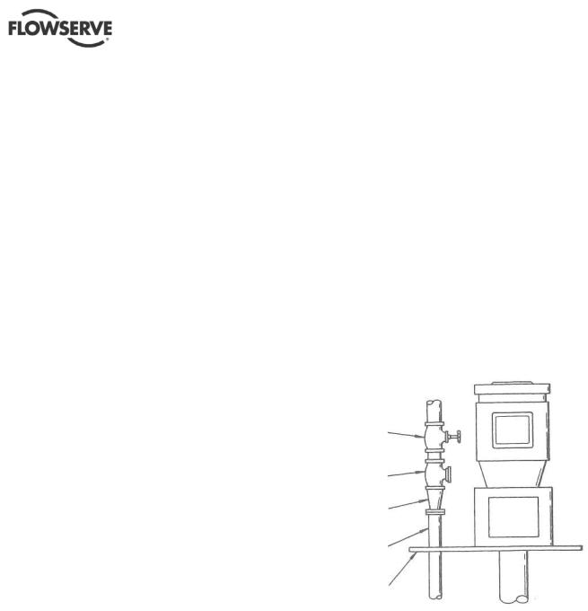
d)After the pump discharge, the increaser should be the first item in the discharge line, followed by the check valve and gate valve, respectively. See Figure 4-1.
e)It is recommended that pressure indicating devices be installed before and after the valves in the discharge line to verify the pump is not being run dry and that the discharge valves are not closed.
 The check valve is required to prevent back-flow through the pump on shut-down. This flow could cause the impeller to unscrew from the shaft and should be avoided.
 When fluid velocity in the pipe is high, for example, 3 m/s (10 ft/sec) or higher, a rapidly closing discharge valve can cause a damaging pressure surge. A dampening arrangement should be provided in the piping.
FIGURE 4-1
GATE
VALVE
CHECK
VALVE
CONCENTRIC
INCREASER
PUMP.
DISCHARGE
MOUNTING,
PLATE
4.6.2 Suction piping
ESP pumps typically only have strainers attached to the suction flange of the pump casing. An option for an extension from the suction flange is available and is called a tailpipe (see section 8 for cross-sectional drawing). A tailpipe is useful for applications where there is adequate NPSH at the lowest sump level but the discharge pressure is critical and must be maintained at a maximum value compared to using a longer column and shaft.
Page 17 of 64
ESP2 USER INSTRUCTIONS ENGLISH PCN-(71569292) 4-12
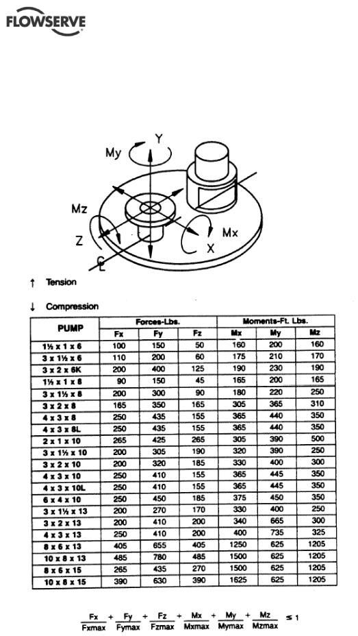
4.6.3 Allowable piping loads
Discharge piping should be constructed to fit to the ESP discharge piping flange. The ESP design can accommodate large piping loads without affecting the operation of the pump, but the installation
FIGURE 4-2 ESP2 nozzle loading
should not impose unnecessary loads to the discharge flange. The allowable piping loads are shown in Figure 4.2.
Page 18 of 64
ESP2 USER INSTRUCTIONS ENGLISH PCN-(71569292) 4-12
4.6.4 Final pump rotation check
After connecting the piping, rotate the pump drive shaft clockwise (viewed from motor end) by hand several complete revolutions to be sure there is no binding and that all parts are free. If piping caused unit to be in a bind, correct piping to relieve strain on the pump.
4.6.5 Auxiliary piping
Check to see if any other connections need to be made to pump, such as injection water to stuffing box for seal or packing lubrication (when furnished) and make the required connections.
4.6.6 Mechanical seal and packing
Pumps supplied with vapor proof construction or pressurized design are furnished with an upper stuffing box (4100) equipped to take mechanical seals or packing (see vapor proof and pressurized design cross-sections in section 8). Installation instructions are in section 5.1.
4.7 Electrical connections
 Electrical connections must be made by a qualified Electrician in accordance with relevant local national and international regulations.
 It is important to be aware of the EUROPEAN DIRECTIVE on potentially explosive areas where compliance with IEC60079-14 is an additional requirement for making electrical connections.
 It is important to be aware of the EUROPEAN DIRECTIVE on electromagnetic compatibility when wiring up and installing equipment on site.
Attention must be paid to ensure that the techniques used during wiring/installation do not increase electromagnetic emissions or decrease the electromagnetic immunity of the equipment, wiring or any connected devices. If in any doubt contact Flowserve for advice.
 The motor must be wired up in accordance with the motor manufacturer's instructions (normally supplied within the terminal box) including any temperature, earth leakage, current and other protective devices as appropriate. The identification nameplate should be checked to ensure the power supply is appropriate.
 See section 5.4, Direction of rotation before connecting the motor to the electrical supply.
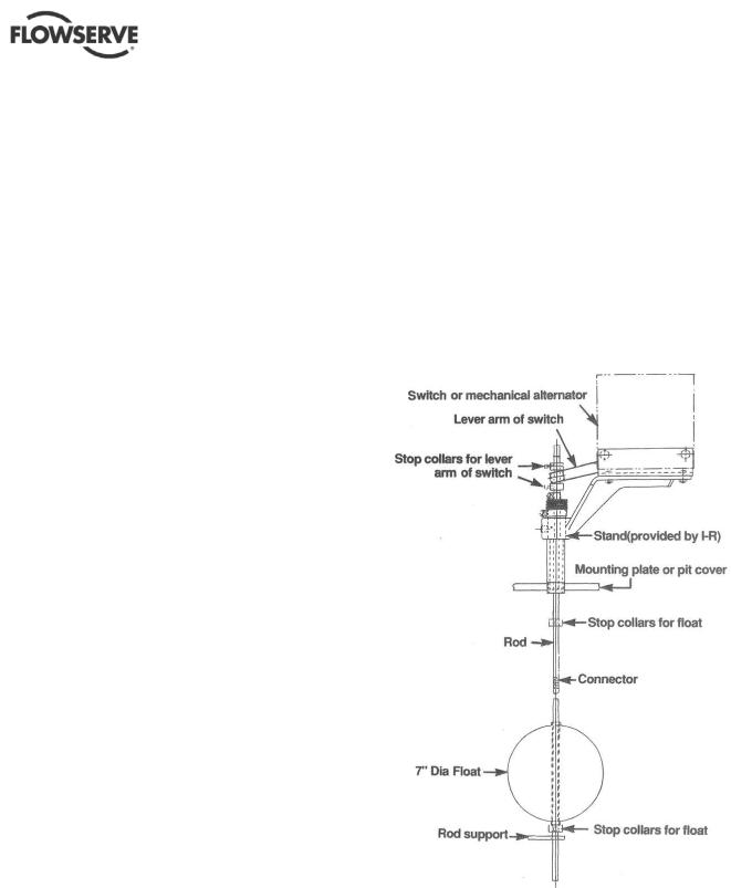
4.8 Level controls
Assemble float control equipment per Figure 4-3 below. Wire the float controls following the diagrams on the next several pages. The stops should be set in accordance with maximum and minimum liquid levels desired and required. Float rods are furnished in kits of a standard length. The rod might have to be cut off to fit the particular installation.
FIGURE 4-3
Some of the wiring diagrams are included on the following pages. If the wiring diagram needed is not included, contact control manufacturer for wiring instructions.
Page 19 of 64
Loading...