


Series F39 Pneumatic Actuator - WCENIM2036-00 05/15
USER INSTRUCTIONS
Worcester Controls/McCANNA Series F39 Pneumatic Actuator
FCD WCENIM2036-00 05/15 |
Installation |
|
Operation |
|
Maintenance |
|
|

Series F39 Pneumatic Actuator - WCENIM2036-00 05/15
 ®
®
Contents
Page
1 |
Safety |
2 |
|
2 |
Description |
2 |
|
3 |
Installation |
3 |
|
4 |
Air supply and electrical installation |
5 |
|
5 |
Air Consumption |
5 |
|
6 |
Electrical Supply (models with integral solenoid only) |
6 |
|
7 |
Installation of accessories |
6 |
|
8 |
Operation |
6 |
|
8.1 |
Basic Actuator – (N Model) |
6 |
|
8.2 |
Actuator With Factory-Supplied Solenoid |
6 |
|
8.3 |
Standard Stroke Times |
7 |
|
8.4 |
Manual Operation |
7 |
|
9 |
Maintenance |
8 |
|
10 |
Spare Parts |
8 |
|
11 |
Troubleshooting |
8 |
|
12 |
Rebuilding instructions |
9 |
|
12.1 Actuator disassembly |
9 |
||
12.2 Actuator reassembly |
11 |
||
13 |
Spring-return actuator |
13 |
|
14 |
Size 05 Exploded view/parts/materials |
14 |
|
15 |
Size 10-50 Exploded view/parts/materials |
15 |
|
1 SAFETY
STOP!
2
The safety terms DANGER, WARNING, CAUTION and NOTE are used in these instructions to highlight particular dangers and/or to provide additional information on aspects that may not be readily apparent.
DANGER: indicates that death, severe personal injury and / or substantial property damage will occur if proper precautions are not taken.
WARNING: indicates that death, severe personal injury and / or substantial property damage can occur if proper precautions are not taken.
CAUTION: indicates that minor personal injury and / or property damage can occur if proper precautions are not taken.
NOTE: indicates and provides additional technical information, which may not be very obvious even to qualified personnel. Compliance with other, not particularly emphasised notes, with regard to transport, assembly, operation and maintenance and with regard to technical documentation (e.g. in the operating instruction, product documentation or on the product itself) is essential, in order to avoid mistakes, which, in themselves, might directly or indirectly cause severe personal injury or property damage.
2 DESCRIPTION
Worcester Controls/McCANNA Series F39 actuators are pneumatic quarter-turn valve actuators. The design utilizes a double-rack, single pinion concept, with each rack integrally cast to a piston. On sizes 10-50, both pistons are supported and centered by large, stainless steel guide rods that are also used to control the rotation of actuator via externally mounted stroke adjustment screws. In double-acting units, both pistons are pressurized on both strokes of the actuator.
Standard units feature an extended top shaft for manual override capabilities and a completely modular design which allows simple attachment of a variety of accessories. All units allow the direct mounting a solenoid control block which properly directs supply air to the actuator. On double-acting actuators, the solenoid control block provides independently adjustable speed control for both opening and closing strokes of the actuator. On spring-re- turn actuators only the spring stroke is adjustable.
WARNING: series F39 actuators are electro-mechanical STOP! devices subject to normal wear and tear. Actuator life is dependent upon application and environmental conditions. If applied in hazardous services such as, but not limited to, media temperature extremes, toxins, flamma-
Series F39 Pneumatic Actuator - WCENIM2036-00 05/15
 ®
®
bles, or other services where improper or incomplete operation could produce a safety hazard, it is incumbent upon the system designer and the user to provide proper warning devices such as temperature sensors, oxygen sensors and flow sensors. Flowserve also recommends that the optional auxiliary limit switches be used for monitoring and/or electrical interlock.
CAUTION: When actuator is installed in outdoor conditions, water can enter the exhaust holes of the double-acting solenoid block, and then freeze. Flowserve suggests a cover be used, or mount the actuator such that the solenoid block is upside down.
Do not install F39S (spring-return) models with air connection in end cap or with integral solenoid vertical, without proper precautions to eliminate the ingress of water spray or rainfall. Exposed end cap or solenoid vent port will allow water to accumulate in spring chambers.
Flowserve recommends that all products which must be stored prior to installation be stored indoors, in an environment suitable for human occupancy. Do not store product in areas where exposure to relative humidity above 85%, acid or alkali fumes, radiation above normal background, ultraviolet light, or temperatures above 120 °F or below 40 °F may occur. Do not store within 50 feet of any source of ozone.
NOTE: included in all F39 actuator accessory and Repair kits is a rebuild/accessory addition label, which is to be marked with a permanent marker and then applied to the actuator after an accessory kit has been installed or an actuator has been repaired.
3 INSTALLATION
NOTE: The Series F39 actuator is normally installed with its major axis parallel to the pipe line (this is mandatory when mounting actuator to 90° V1 Diverter/Three-Way (D44 and T44) valves and CPT valves. The actuator can be oriented above, beside or beneath the valve without affecting its operation.
Sizes 10-35 Rev. R7 actuators may come with an ISO locating ring, used for optional ISO mounting.
Size 40-50 Rev. R7 actuators have an integral ISO location ring.
3.1Determine mode of operation desired (normally open or normally closed) of the valve.
3.2Determine desired quadrant for bracket attachment and direction of mounting of actuator (in-line or cross-line).
3.3Attach mounting bracket to actuator using four (4) cap screws and lock washers provided in mounting kit. To avoid any damage to the Series F39 actuator body, ONLY the proper length screws supplied with the mounting kit should be used. For small size top mount style valves, attach bracket such that bracket nameplate will be to side of valve.
3.4For mounting to 818/828 Series valves, insert ISO locating ring into groove on bottom of actuator before attaching to bracket. Ring can be permanently held in groove by applying Loctite® 638 to ring before inserting in groove.
NOTE: Size 05F39, if furnished with factory solenoid, shall be “cross-line” mounted (i.e. at 90 degrees to the pipe run) to ensure adequate clearance for air connections.
3.5Prepare valve for actuation:
CAUTION: Ball valves can trap pressurized media in the cavity. If it is necessary to remove any valve body bolts, stem nuts, or remove valve from the line, and if the valve is or has been in operation, make sure there is NO pressure to or in the valve and operate valve one full cycle.
3.5.1Valve models 45 (2½”–6”), 59 (2”–4”), 51/52 (½”–10”), 151/301 (3”–6”), 82/83 (½”–10”), 818/828 (2”–8”), 94 (½”–6”), 44 (¼”–2”), 59 (¼”–1½”), WK70/WK74 and H71 (½”–2”):
NOTE: For above listed valves, it is not necessary to remove any valve body bolts or remove valve from line in order to mount actuator.
3.5.2Rotate valve ball and stem to position necessary to achieve desired operation. If any valve information is marked on stop plate or handle, it will be necessary to transfer this information to the bracket nameplate.
3.5.3For ¼”–2” 44, ½”–2” WK70/WK74, ¼”–1½” 59, and ½”–1½” H71 series top-mount style valves, and ½”–2” 51/52, ½”–1½” 82/83 series valves with high-cycle stem packing as standard, remove handle nut, lockwasher, handle, separate stop plate (if any), retaining nut and stop pin(s). Add the two additional Belleville washers with their larger diameter sides touching each other. Add the self-locking nut to the stem and tighten while holding the stem flats with wrench. Tighten until Belleville washers are flat — the nut will “bottom” — and then back nut off 1/3 of a turn. The two additional Belleville washers and the self-locking nut are included in the mounting kit.
CAUTION: Due to the design of the self-locking stem nut, resistance will be felt as it threads onto the stem assembly. Ensure the Belleville washers are fully flattened before backing off.
3
Series F39 Pneumatic Actuator - WCENIM2036-00 05/15
 ®
®
3.5.4For 2” 59, H71, 82/83, and 2½” 45, 82/83 valves, and valves 3” and larger with square stem, remove handle assembly, retaining nut, stop and stop screws. Replace with valve stem spacer or, if valve has graphite stem packing, with two Belleville washers (except 8”,10” 82/83 and 10” 51/52), and replace retaining nut.
NOTE: Belleville washers are installed with their larger diameter sides touching each other. Do not use stem spacer when Belleville washers are used. Using a wrench to prevent stem from turning, tighten retaining nut until stem packing is fully compressed or Bellevilles, if used, are fully flattened, then back off nut 1/6 turn. Excessive tightening causes higher torque and shorter seal life.
NOTE: Large valves with V51 high-cycle stem packing option installed, identified by two Belleville washers installed and handle assembly, stop and stop screws removed, and 818/828 series valves, do not require stem area disassembly.
3.5.5For 2”–8” 818/828 valves, remove handle assembly, locking plates and hardware, and stop screw (if any). Do not remove stop plate (2”–6” sizes) or spacer (8” size).
3.5.6For ½”–2” 94 valves, remove handle (if any). Do not remove gland plate or gland bolts.
3.5.7For 3”–6” 94 and 2”–8” E818/828 valves, remove handle assembly, stop, and spacer (if any). Do not remove gland plate or gland bolts.
3.6Attach bracket/actuator assembly to valve as follows:
3.6.1Center coupling on valve stem.
3.6.2Lower mounting bracket/actuator assembly over coupling and onto valve, making sure that female star drive actuator shaft engages in the correct orientation with the coupling.
3.6.3Secure bracket to valve using cap screws and lockwashers, or bolts and nuts provided in mounting kit. Tighten securely. For small size top-mount style valves, bracket nameplate will be to side of valve.
3.6.4Install set screws (if any) in coupling and tighten securely.
3.6.5Determine if mode of operation (air to open or close/fail open or closed) is as desired; if not:
•Air to Open or Close - On all sizes of F39 double-acting and spring-return actuators, the female drive shaft is a star drive. This allows selection of either mode of operation by indexing the coupling (including valve ball and stem) 90° to the actuator shaft, while keeping the actuator in an in-line orientation.
•Fail Open or Fail Close - The normal method of mounting is to have the actuator in line with the pipe line and the valve and actuator in the “FAIL-CLOSED” (Clockwise to close) position. “FAIL-OPEN” can be achieved using the method above but the actuator will then work
as Clockwise to open).
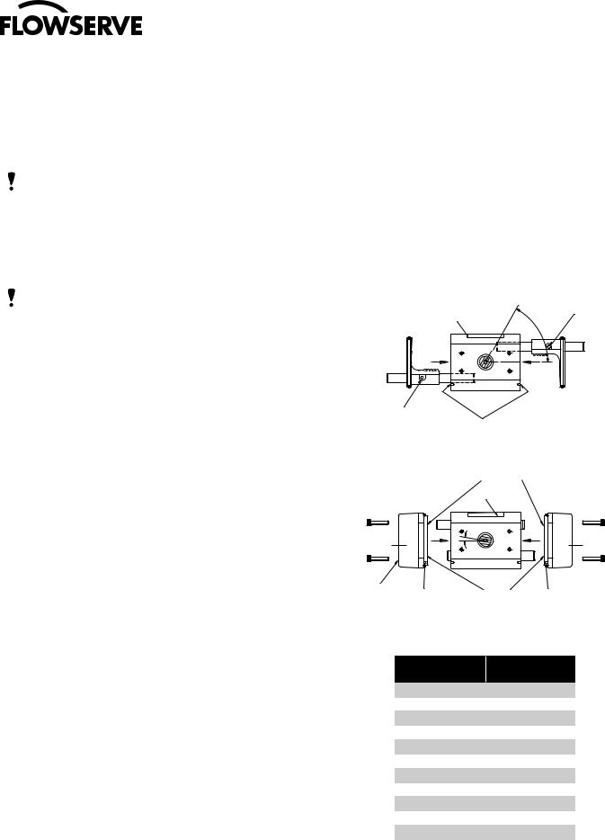
•For “FAIL-OPEN” but with Clockwise to close operation, the pistons in the actuator will need to be removed and reassembled from the opposite ends of the actuator (keeping the guide rods the same sides relative to the body). This will result in a slight offset of pinion position on some sizes. See below:
Position of pinion |
|
|
flats and groove |
Blank support rod |
|
(60º approx.) |
||
(without cross hole) |
||
Label |
||
|
Inlet support rod |
Label |
|
|
(with cross hole) |
Foolproof pin |
||
|
|||
|
|
location holes |
|
|
|
Bores containing |
|
|
|
bearings only |
|
|
|
Label |
Inlet |
|
# |
Limit Stop |
End Cap |
|
End Cap |
|
|
|
||
Inlet port |
Foolproof pin |
|
Bores containing Foolproof pin |
|
|
||
|
|
|
bearings and |
|
|
|
0-rings |
Actuator |
Pinion Offset |
Size |
Angle # |
05 |
0° |
10 |
10° |
15 |
2° |
20 |
2° |
25 |
2° |
30 |
2° |
33 |
2° |
35 |
2° |
40 |
0° |
42 |
0° |
45 |
0° |
50 |
12° |
4

Series F39 Pneumatic Actuator - WCENIM2036-00 05/15
 ®
®
3.6.6Determine position indication. Buttons on position indicator are set up to show valve closed on in-line mounting, i.e., pistons together on actuator. If different indication is required:
•Check which visual indication is required.
•Check that indicator, when located on actuator shaft, will show correct indication.
•To change indication, on size 10 to 20 push out (remove) red and white buttons and reassemble in opposite positions. For sizes 25 and above remove the complete indicator and orientate to the correct position.
•Locate indicator on actuator shaft flats. Press firmly until location nibs snap into recess on actuator shaft.
4 AIR SUPPLY AND ELECTRICAL INSTALLATION
4.1Air Supply:
The Series F39 Actuator is factory lubricated. For optimum operation, the use of filtered and lubricated air is recommended.
4.2Air Supply Pressure:
Standard double-acting actuators require 40–120 psig supply air. Spring-return actuators require 80–120 psig supply air. Spring-return actuators can also be set up to operate on supply air pressures ranging from 40–80 psig by using fewer springs. See “Rebuilding Instructions”, Spring-Return Actuator, paragraph 1 on page 13 for proper number and location of springs for reduced supply air pressures.
WARNING: Air pressure greater than 120 psi must not be STOP! applied.
4.3Air Supply Connections:
4.3.1No Integral Solenoid:
Double-Acting (N Models) – Connect air supply lines to both NPT (1/8” on size 05, ¼” on sizes 10–50) ports.
Spring-Return (SN Models) – Connect air supply line to the outboard NPT (1/8” on size 05, ¼” on sizes 10–50) port.
For sizes 10–50, the ports are on the solenoid end cap. The solenoid end cap is the one on the right end of the actuator when looking at the nameplate. For 05 size only, the ports are on the solenoid block interface plate on back of actuator when looking at the nameplate. For size 05 spring-return it is on the back and near center of actuator.
4.3.2With Integral Solenoid:
Connect air supply line to the NPT (1/8” on four-way double-acting blocks, ½” on threeway spring-return blocks) port on the solenoid block.
4.4Recommended Tubing Sizes:
In order to provide sufficient flow of supply air to the Series F39 actuator, the following tubing sizes are recommended:
Actuator Size |
Runs Up To |
Runs Over |
|||
4 Ft. Long |
4 Ft. Long |
||||
|
|||||
|
|
|
|
||
05, 10, 15, 20, 25 |
1 |
/ |
¼ |
||
|
8 |
|
|
||
30, 33, 35, 40, 42, 45 |
¼ |
3 |
/ |
||
|
|
|
8 |
||
50 |
¼ |
½ |
|||
|
|
|
|
|
|
5.Air Consumption
The following chart shows the amount of pressurized (80 psig) air consumed per stroke in cubic feet. To determine the total amount of air consumed per complete cycle for double-acting actuators, simply add the volumes for both the opening and closing strokes together; for spring return units, the total volume of air consumed is the volume shown for the opening stroke.
Actuator Size |
Air consumption cu. ft. |
||
|
|
||
Opening Stroke |
Closing Stroke |
||
|
|||
|
|
|
|
05F39 |
.01 |
.01 |
|
|
|
|
|
10F39 |
.04 |
.05 |
|
|
|
|
|
15F39 |
.08 |
.09 |
|
|
|
|
|
20F39 |
.16 |
.17 |
|
|
|
|
|
25F39 |
.28 |
.30 |
|
|
|
|
|
30F39 |
.43 |
.47 |
|
|
|
|
|
33F39 |
.65 |
1.1 |
|
|
|
|
|
35F39 |
.90 |
1.3 |
|
|
|
|
|
40F39 |
1.3 |
1.4 |
|
|
|
|
|
42F39 |
1.7 |
3.3 |
|
|
|
|
|
45F39 |
3.1 |
4.6 |
|
|
|
|
|
50F39 |
5.5 |
7.0 |
|
|
|
|
|
5
 Loading...