Flowserve NRS 1-3b User Manual [de, en, fr, es]

NRS 1-3 b
Betriebsanleitung 808228-01
Schaltverstärker NRS 1-3 b
Installation Instructions 808228-01
Level Switch NRS 1-3 b
Instructions de montage et de mise en service 808228-01
Commutateur-amplificateur NRS 1-3 b
Instrucciones de montaje y servicio 808228-01
Amplificador de maniobra NRS 1-3 b

NRS 1-3 b
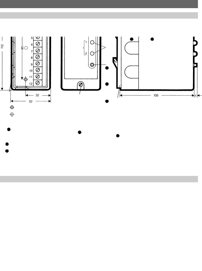
Maße / Dimensions / Dimensions / Dimensiones
Unterteil mit Anschlußklemmen |
Frontansicht |
Seitenansicht |
Base with terminals |
Front view |
Side view |
Partie inférieure avec bornier de raccordement |
Vue de face |
Vue de côté |
Base con bornes de conexión |
Vista frontal |
Vista lateral |
|
8 |
9 |
1
2
3
5
4
10
6
7
Fig. 1: Dimensiones de instalación del NRS 1-3 b, profundidad 106 mm
Anschlußplan / Wiring Diagram / Schéma de raccordement*) / Esquema de conexión
*) Attention: Pour l’exécution avec panneau frontal en français appliquer le schéma de raccordement indiqué dans le capot de l’appareil.
interne Verriegelung wirksam link: internal interlocking provided
shunt verrouillage interne en service para enclavamiento interior
Fig. 2: Anschlußplan Schaltverstärker NRS 1-3 b, gezeichnete Kontaktstellungen: stromlos bzw. Alarm
Fig. 2: Wiring diagram for level switch type NRS 1-3 b, drawn position of contacts: relays deenergized, i. e. alarm
Fig. 2: Schéma de raccordement du commutateur-amplificateur type NRS 1-3 b, contacts représentés en position repos ou alarme Fig. 2: Esquema de conexión del amplificador de maniobra NRS 1-3 b, posición de contactos representada: sin corriente o alarma

DEUTSCH
Gefahr
Die Klemmleiste des NRS 1-3 steht während des Betriebs unter Spannung.
Schwere Verletzungen durch elektrischen Strom sind möglich.
Vor Arbeiten im Gerät Anlage spannungsfrei schalten.
Aufgabe
Prüfbarer Zweikanal-Wasserstandbegrenzer in Verbindung mit GESTRA Niveau-Mehr- fachelektrode ER 5 . . . oder Niveau-Elektrode ER 16.
Einbau
1. Mit Schnappbefestigung
Gerät auf 35-mm-Normschiene aufrasten.
2. Ohne Schnappbefestigung
Haubenschrauben lösen und Haube vom Unterteil abziehen. Schnappbefestigung abschrauben. Im Unterteil die vormarkierten Stellen mit Bohrer 4,3 durchbohren. Unterteil mit zwei Schrauben M 4 auf Grundplatte montieren.
Elektrischer Anschluß
Anschluß gemäß Anschlußplan (siehe links oder Haubenunterseite des Schaltverstärkers), Netzspannung wie auf Typenschild angegeben. Als Elektrodenzuleitung wird geschirmtes Kabel I-Y (St) Y 2 x 2 x 0,6 o. ä. empfohlen,
Länge max. 100 m. Schirm nur an Klemme 12 anschließen, nicht jedoch auch elektrodenseitig. Der Schirm darf keine galvanische Berührung mit Schutzleiterpotential haben.
Zum Einführen der Kabel seitliche Kabeldurchführungen im Unterteil durchstoßen oder herausziehen. Nach Anschluß Haube wieder aufstecken und Schrauben anziehen.
Prüfungen
1.Bei angeschlossener, jedoch ausgetauchter Elektrode müssen beide Lampen A1, A2 leuchten.
2.Bei eingetauchter Elektrode oder Verbinden der Meßspitze mit dem Elektrodengehäuse durch einen Draht dürfen Lampen A1, A2 nicht leuchten. Wird zusätzlich Taste „Test“ betätigt, müssen die Lampen wieder aufleuchten.
3.Die Elektroden-Speisespannung beträgt 11 VAC ± 20 %, meßbar zwischen der Elektrodenspitze und dem Masseanschluß
mit einem hochohmigen Instrument ( 100 kΩ/V) bei nicht eingetauchter Elektrode.
4.Sind die Klemmen 9 und 10 gebrückt, ist die interne Verriegelung aktiviert, d. h. nach Wiedereintauchen der Elektrode wird so lange Wassermangel signalisiert, bis die Entriegelungstaste gedrückt ist.
Achtung
Vor jedem Abziehen der Haube muß das Gerät spannungsfrei geschaltet werden.
Entstörung induktiver
Verbraucher
Beim Abschalten induktiver Verbraucher entstehen Spannungsspitzen, die ein Mehrfaches der Netzspannung erreichen können. Dadurch werden
1.die Funktion von Steuer-, Meßund Regelanlagen teilweise erheblich beeinträchtigt und
2.die Kontaktlebensdauer des Steuerrelais durch Lichtbögen reduziert.
Es wird daher empfohlen, induktive Verbraucher mit handelsüblichen RC-Kombinationen zu beschalten (z. B. 0,1 µF/100 Ω).
Zu Bild 1:
1Entriegeln RESET
2MIN/NW
3TEST
4Schrauben zum Lösen der Haube vom Unterteil
5Kabeldurchführungen
6Montagebohrungen,
mit Bohrer 4,3 aufbohren
7Montagebohrung für Schnappbefestigung
8Unterteil
9Haube
10Schnappbefestigung für Tragschiene TS 35 x 15 DIN 46 277
ENGLISH
Danger
The terminal strip of the NRS 1-3 is live during operation. This presents the danger of electric shock. Cut off power supply before fixing or removing the housing cover.
Purpose
Two-channel low-water-level alarm with test button used in combination with GESTRA multiple level control electrode type ER 5 . . .
or level control electrode type ER 16.
Installation
1. With mounting clip
Snap unit onto 35 mm supporting rail.
2. Without mounting clip
Loosen cover screws and unplug unit from its base. Unscrew mounting clip. Drill the holes in the base marked 4.3 mm. Fasten base with two screws M 4 onto mounting panel.
Wiring
Wiring should be carried out in accordance with wiring diagram (see diagram opposite or inside cover of plug-in unit). The mains voltage is indicated on the name plate. For wiring to the electrode screened cable, e. g. 2 x 2 x 0.6 mm2 is recommended. The max.
length must not exceed 100 m. The screen should only be connected to terminal 12 of the NRS 1-3, but not at the electrode. The screen must not have contact with any metal part of the plant.
To introduce cable, remove cable entries in the base. After wiring replace cover and tighten screws.
Performance Tests
1.With the electrode connected, but exposed, both lamps MIN/LW 1 and 2 2 must light up.
2.If the electrode is immersed or its measuring tip connected to the electrode body with the aid of a wire, lamps 1 and 2 must not light up. After pushing the button “Test”, the lamps should light up again.
3.The electrode supply voltage is 11 VAC
± 20 %. It can be measured with the electrode exposed between the electrode tip
and the earth connection with the aid of a high-impedance voltmeter ( 100 kΩ/V).
4.If the terminals 9 and 10 are linked, the internal interlocking is activated, i. e. on reimmersion of the electrode the level switch continues to signal low-level alarm unless the “Reset” button has been pressed.
Note
Before unplugging cover of NRS 1-3 cut off power.
Relay Arc Suppression for Inductive Loads
When switching off inductive loads voltage peaks are produced that may reach several times the mains voltage. The result is:
1.The operation of control and measuring systems may be impaired by interference caused by the voltage peaks.
2.The life of the relay contacts is reduced by the electric arcs formed.
We therefore recommend that inductive loads are provided with commercial arc suppressor RC combinations (e. g. 0.1 µF/100 Ω).
Concerning Figure 1:
1RESET
2MIN/LW
3TEST
4Screws to fasten cover to base
5Cable entries
6Holes to be drilled to 4.3 mm diameter for installation of unit in boiler panel
7Hole drilled for mounting clip
8Base
9Cover
10 Mounting clip for 35 mm supporting rail
 Loading...