


®
Pump Division
Types: MNV and MNZ
(Vertical long shafted)
CENTRIFUGAL PUMPS
USER INSTRUCTIONS:
INSTALLATION, OPERATION, MAINTENANCE
PCN = 71569188 1104 (E) |
(incorporating MNV/MNZ.IOM) |
 These instructions should be read prior to installing operating, using and maintaining this equipment.

MNV & MNZ USER INSTRUCTIONS ENGLISH 71569188 11/04
 ®
®
CONTENTS
|
|
PAGE |
CONTENTS............................................................... |
2 |
|
1 INTRODUCTION AND SAFETY........................... |
3 |
|
1.1 |
General ........................................................... |
3 |
1.2 |
CE marking and approvals.............................. |
3 |
1.3 |
Disclaimer ....................................................... |
3 |
1.4 |
Copyright......................................................... |
3 |
1.5 |
Duty conditions ............................................... |
3 |
1.6 |
Safety.............................................................. |
4 |
1.7 |
Nameplate and warning labels ....................... |
8 |
1.8 |
Noise level ...................................................... |
9 |
1.9 |
Specific machine performance...................... |
10 |
2 TRANSPORT AND STORAGE........................... |
10 |
|
2.1 |
Consignment receipt and unpacking ............ |
10 |
2.2 |
Handling........................................................ |
10 |
2.3 |
Lifting............................................................. |
10 |
2.4 |
Storage.......................................................... |
11 |
2.5 |
Recycling and end of product life.................. |
12 |
3 DESCRIPTION .................................................... |
12 |
|
3.1 |
Nozzle configurations.................................... |
13 |
3.2 |
Name nomenclature...................................... |
14 |
3.3 |
Design of major parts.................................... |
14 |
3.4 |
Performance and operating limits ................. |
15 |
4 INSTALLATION................................................... |
16 |
||
4.1 |
|
Location ........................................................ |
16 |
4.2 |
|
Part assemblies ............................................ |
16 |
4.3 |
|
Foundation .................................................... |
16 |
4.4 |
|
Grouting ........................................................ |
17 |
4.5 |
|
Initial alignment ............................................. |
18 |
4.6 |
|
Piping ............................................................ |
19 |
4.7 |
|
Electrical connections ................................... |
21 |
4.8 |
|
Final shaft alignment check .......................... |
21 |
4.9 |
|
Protection systems........................................ |
21 |
5 COMMISSIONING, START-UP, OPERATION AND |
|||
SHUTDOWN.................................................... |
22 |
||
5.1 |
|
Pre-commissioning procedure ...................... |
22 |
5.2 |
|
Pump Lubrication .......................................... |
22 |
5.3 |
|
Impeller clearance......................................... |
24 |
5.4 |
|
Direction of rotation....................................... |
24 |
5.5 |
|
Guarding ....................................................... |
25 |
5.6 |
|
Priming and auxiliary supplies ...................... |
25 |
5.7 |
|
Starting the pump.......................................... |
25 |
5.8 |
|
Running or operation .................................... |
26 |
5.9 |
|
Stopping and shutdown................................. |
28 |
5.10 |
Hydraulic, mechanical and electrical duty... |
28 |
|
6 MAINTENANCE .................................................. |
28 |
||
6.1 |
|
Maintenance schedule.................................. |
29 |
6.2 |
|
Spare parts.................................................... |
35 |
6.3 |
|
Suggested spares and consumable items.... |
36 |
6.4 |
Tools required ............................................... |
36 |
|
6.5 |
|
Fastener torques........................................... |
36 |
6.6 |
|
Renewal clearances...................................... |
36 |
|
PAGE |
|
6.7 Disassembly .................................................. |
37 |
|
6.8 |
Examination of parts...................................... |
39 |
6.9 Assembly ....................................................... |
40 |
|
7 FAULTS; CAUSES AND REMEDIES.................. |
41 |
|
8 PARTS LIST AND DRAWINGS........................... |
43 |
|
8.1 |
MNV cross section and parts list ................... |
43 |
8.2 |
MNZ cross section and parts list ................... |
45 |
9 CERTIFICATION ................................................. |
46 |
|
10 OTHER RELEVANT DOCUMENTATION AND |
|
|
MANUALS........................................................ |
46 |
|
10.1 |
Supplementary user instructions ................. |
46 |
10.2 Change notes .............................................. |
46 |
|
INDEX |
|
|
|
PAGE |
|
Alignment of shafting (see 4.3, 4.5 and 4.7) |
|
|
CE marking and approvals (1.2) ................................ |
3 |
|
Clearances (see 6.6, Renewal clearances) ............. |
36 |
|
Commissioning and operation (see 5) ..................... |
22 |
|
Configurations (3.1).................................................. |
13 |
|
Direction of rotation (5.4).......................................... |
24 |
|
Dismantling (see 6.7, Disassembly)......................... |
37 |
|
Duty conditions (1.5) .................................................. |
3 |
|
Electrical connections (4.7)...................................... |
21 |
|
Examination of parts (6.8)........................................ |
39 |
|
Faults; causes and remedies (7.0)........................... |
41 |
|
General assembly drawings (see 8) ........................ |
43 |
|
Grouting (4.4) ........................................................... |
17 |
|
Guarding (5.5) .......................................................... |
24 |
|
Handling (2.2)........................................................... |
10 |
|
Hydraulic, mechanical and electrical duty (5.10) ..... |
28 |
|
Lifting (2.3) ............................................................... |
10 |
|
Location (4.1) ........................................................... |
16 |
|
Lubrication schedule (see 5.2, Pump lubricants)..... |
22 |
|
Maintenance schedule (6.1)..................................... |
29 |
|
Piping (4.6)............................................................... |
19 |
|
Priming and auxiliary supplies (5.6) ......................... |
25 |
|
Reassembly (see 6.9, Assembly) ............................ |
40 |
|
Replacement parts (see 6.3 and 6.4)....................... |
36 |
|
Safety, protection systems (see 1.6 and 4.9) |
|
|
Sound level (see 1.8, Noise level) ............................. |
9 |
|
Specific machine performance (1.9) ........................ |
10 |
|
Starting the pump (5.7) ............................................ |
25 |
|
Stopping and shutdown (5.9) ................................... |
26 |
|
Storage (2.4) ............................................................ |
11 |
|
Supplementary user instructions (10.1) ................... |
46 |
|
Tools required (6.4).................................................. |
36 |
|
Torques for fasteners (6.5) ...................................... |
36 |
|
Page 2 of 47

MNV & MNZ USER INSTRUCTIONS ENGLISH 71569188 11/04
 ®
®
1 INTRODUCTION AND SAFETY
1.1 General
 These instructions must always be kept close to the product's operating location or directly with the product.
Flowserve's products are designed, developed, and manufactured with state-of-the-art technologies in modern facilities. The unit is produced with great care and commitment to continuous quality control, utilizing sophisticated quality techniques, and safety requirements.
Flowserve is committed to continuous quality improvement and being at service for any further information about the product in its installation and operation or about its support products, repair and diagnostic services.
These instructions are intended to facilitate familiarization with the product and its permitted use. Operating the product in compliance with these instructions is important to help ensure reliability in service and avoid risks. The instructions may not take into account local regulations; ensure such regulations are observed by all, including those installing the product. Always coordinate repair activity with operations personnel, and follow all plant safety requirements and applicable safety and health laws and regulations.
 These instructions should be read prior to installing, operating, using and maintaining the equipment in any region worldwide. The equipment must not be put into service until all the conditions relating to safety noted in the instructions, have been met.
and Approvals. To confirm the Approvals applying and if the product is CE marked, check the serial number plate markings and the Certification. (See section 9, Certification.)
1.3 Disclaimer
Information in these User Instructions is believed to be reliable. In spite of all the efforts of Flowserve Pump Division to provide sound and all necessary information the content of this manual may appear insufficient and is not guaranteed by Flowserve as to its completeness or accuracy.
Flowserve manufactures products to exacting International Quality Management System Standards as certified and audited by external Quality Assurance organizations. Genuine parts and accessories have been designed, tested, and incorporated into the products to help ensure their continued product quality and performance in use. As Flowserve cannot test parts and accessories sourced from other vendors the incorrect incorporation of such parts and accessories may adversely affect the performance and safety features of the products. The failure to properly select, install, or use authorized Flowserve parts and accessories is considered to be misuse. Damage or failure caused by misuse is not covered by Flowserve's warranty. In addition, any modification of Flowserve products or removal of original components may impair the safety of these products in their use.
1.4 Copyright
All rights reserved. No part of these instructions may be reproduced, stored in a retrieval system or transmitted in any form or by any means without prior permission of Flowserve Pump Division.
1.2 CE marking and approvals
It is a legal requirement that machinery and equipment put into service within certain regions of the world shall conform with the applicable CE Marking Directives covering Machinery and, where applicable, Low Voltage Equipment, Electromagnetic Compatibility (EMC), Pressure Equipment Directive (PED) and Equipment for Potentially Explosive Atmospheres (ATEX).
Where applicable the Directives and any additional Approvals cover important safety aspects relating to machinery and equipment and the satisfactory provision of technical documents and safety instructions. Where applicable this document incorporates information relevant to these Directives
1.5 Duty conditions
This product has been selected to meet the specifications of your purchaser order. The acknowledgement of these conditions has been sent separately to the Purchaser. A copy should be kept with these instructions.
 The product must not be operated beyond the parameters specified for the application. If there is any doubt as to the suitability of the product for the application intended, contact Flowserve for advice, quoting the serial number.
If the conditions of service on your purchase order are going to be changed (for example liquid pumped, temperature or duty) it is requested that the user seeks Flowserve’s written agreement before start up.
Page 3 of 47

MNV & MNZ USER INSTRUCTIONS ENGLISH 71569188 11/04
 ®
®
1.6 Safety
1.6.1 Summary of safety markings
These User Instructions contain specific safety markings where non-observance of an instruction would cause hazards. The specific safety markings are:
 This symbol indicates electrical safety instructions where non-compliance will involve a high risk to personal safety or the loss of life.
 This symbol indicates safety instructions where non-compliance would affect personal safety and could result in loss of life.
 This symbol indicates “hazardous and toxic fluid” safety instructions where non-compliance would affect personal safety and could result in loss of life.
 This symbol indicates safety instructions where non-compliance will involve some risk to safe operation and personal safety and would damage the equipment or property.
 This symbol indicates explosive atmosphere zone marking according to ATEX. It is used in safety instructions where non-compliance in the hazardous area would cause the risk of an explosion.
 This sign is not a safety symbol but indicates an important instruction in the assembly process.
1.6.2 Personnel qualification and training
All personnel involved in the operation, installation, inspection and maintenance of the unit must be qualified to carry out the work involved. If the personnel in question do not already possess the necessary knowledge and skill, appropriate training and instruction must be provided.
If required the operator may commission the manufacturer/supplier to provide applicable training.
Always coordinate repair activity with operations and health and safety personnel, and follow all plant safety requirements and applicable safety and health laws and regulations.
1.6.3 Safety action
This is a summary of conditions and actions to prevent injury to personnel and damage to the environment and to equipment. For products used in potentially explosive atmospheres section 1.6.4 also applies.
 NEVER DO MAINTENANCE WORK WHEN THE UNIT IS CONNECTED TO POWER
 GUARDS MUST NOT BE REMOVED WHILE THE PUMP IS OPERATIONAL
 DRAIN THE PUMP AND ISOLATE PIPEWORK BEFORE DISMANTLING THE PUMP
The appropriate safety precautions should be taken where the pumped liquids are hazardous.
 FLUORO-ELASTOMERS (When fitted.) When a pump has experienced temperatures over 250 ëC (482 ëF), partial decomposition of fluoroelastomers (example: Viton) will occur. In this condition these are extremely dangerous and skin contact must be avoided.
 HANDLING COMPONENTS
Many precision parts have sharp corners and the wearing of appropriate safety gloves and equipment is required when handling these components. To lift heavy pieces above 25 kg (55 lb) use a crane appropriate for the mass and in accordance with current local regulations.
 THERMAL SHOCK
Rapid changes in the temperature of the liquid within the pump can cause thermal shock, which can result in damage or breakage of components and should be avoided.
 APPLYING HEAT TO REMOVE IMPELLER There may be occasions when the impeller has either been shrunk fit onto the pump shaft or has become difficult to remove due to products that are corrosive in nature.
If you elect to use heat to remove the impeller, it must be applied with a great care and before applying heat ensure any residual hazardous liquid trapped between the impeller and pump shaft is thoroughly drained out through the impeller keyway to prevent an explosion or emission of toxic vapor.
Impeller design vary and so are the heat, applying location and the duration of heat application. Contact your nearest Flowserve service center for help.
Page 4 of 47

MNV & MNZ USER INSTRUCTIONS ENGLISH 71569188 11/04
 ®
®
 HOT (and cold) PARTS
If hot or freezing components or auxiliary heating supplies can present a danger to operators and persons entering the immediate area action must be taken to avoid accidental contact. If complete protection is not possible, the machine access must be limited to maintenance staff only, with clear visual warnings and indicators to those entering the immediate area.
 Bearing housings must not be insulated to avoid drive motor and bearing heat up.
If the temperature is greater than 68 °C (175 °F) or below 5 °C (20 °F) in a restricted zone, or exceeds local regulations, action as above shall be taken.


 HAZARDOUS LIQUIDS
When the pump is handling hazardous liquids care must be taken to avoid exposure to the liquid by appropriate siting of the pump, limiting personnel access and by operator training. If the liquid is flammable and/or explosive, strict safety procedures must be applied.
Gland packing must not be used when pumping hazardous liquids.
 PREVENT EXCESSIVE EXTERNAL PIPE LOAD
Do not use pump as a support for piping. Do not mount expansion joints, unless allowed by Flowserve in writing, so that their force, due to internal pressure, acts on the pump flange.
 ENSURE CORRECT LUBRICATION (See section 5, Commissioning, start-up, operation and shutdown.)
 START THE PUMP WITH OUTLET VALVE PARTLY OPENED
(Unless otherwise instructed at a specific point in the User Instructions.)
This is recommended to minimize the risk of overloading and damaging the pump motor at full or zero flow. Pumps may be started with the valve further open only on installations where this situation cannot occur. The pump outlet control valve may need to be adjusted to comply with the duty following the run-up process. (See section 5, Commissioning start-up, operation and shutdown.)
 NEVER RUN THE PUMP DRY
 INLET VALVES TO BE FULLY OPEN WHEN PUMP IS RUNNING
Running the pump at zero flow or below the recommended minimum flow continuously will cause damage to the seal.
 DO NOT RUN THE PUMP AT ABNORMALLY HIGH OR LOW FLOW RATES Operating at a flow rate higher than normal or at a flow rate with no backpressure on the pump may overload the motor and cause cavitation. Low flow rates may cause a reduction in pump/bearing life, overheating of the pump, instability and cavitation/ vibration.
1.6.4 Products used in potentially explosive atmospheres
 Measures are required to:
∙Avoid excess temperature
∙Prevent build up of explosive mixtures
∙Prevent the generation of sparks
∙Prevent leakages
∙Maintain the pump to avoid hazard
The following instructions for pumps and pump units when installed in potentially explosive atmospheres must be followed to help ensure explosion protection. Both electrical and non-electrical equipment must meet the requirements of European Directive 94/9/EC.
1.6.4.1 Scope of compliance
 Use equipment only in the zone for which it is appropriate. Always check that the driver, drive coupling assembly, seal and pump equipment are suitably rated and/or certified for the classification of the specific atmosphere in which they are to be installed.
Where Flowserve has supplied only the bare shaft pump, the Ex rating applies only to the pump. The party responsible for assembling the pump set shall select the coupling, driver and any additional equipment, with the necessary CE Certificate/ Declaration of Conformity establishing it is suitable for the area in which it is to be installed.
The output from a variable frequency drive (VFD) can cause additional heating affects in the motor and the ATEX Certification for the motor must state that it is covers the situation where electrical supply is from the VFD. This particular requirement still applies even if the VFD is in a safe area.
Page 5 of 47

MNV & MNZ USER INSTRUCTIONS ENGLISH 71569188 11/04
 ®
®
1.6.4.2 Marking
An example of ATEX equipment marking is shown below. The actual classification of the pump will be engraved on the nameplate.
II 2 GD c IIC 135 ºC (T4)
Equipment Group I = Mining
II = Non-mining
Category
2 or M2 = High level protection
3 = normal level of protection
Gas and/or Dust G = Gas; D= Dust
c = Constructional safety
(in accordance with prEn13463-5)
Gas group (Equipment Category 2 only) IIA – Propane (typical)
IIB – Ethylene (typical)
IIC – Hydrogen (typical)
Maximum surface temperature (Temperature Class)
(See section 1.6.4.3.)
1.6.4.3 Avoiding excessive surface temperatures
 ENSURE THE EQUIPMENT TEMPERATURE CLASS IS SUITABLE FOR THE HAZARD ZONE
Pumps have a temperature class as stated in the ATEX Ex rating on the nameplate. These are based on a maximum ambient of 40 °C (104 °F); refer to Flowserve for higher ambient temperatures.
The surface temperature on the pump is influenced by the temperature of the liquid handled. The maximum permissible liquid temperature depends on the temperature class and must not exceed the values in the table that follows.
The temperature rise at the seals and bearings and due to the minimum permitted flow rate is taken into account in the temperatures stated.
Temperature |
Maximum |
Temperature limit of liquid |
|
surface |
handled (* depending on |
||
class to |
|||
temperature |
material and construction |
||
prEN 13464-5 |
|||
permitted |
variant - check which is |
||
|
|||
|
|
lower) |
|
T6 |
85 °C (185 °F) |
Consult Flowserve |
|
T5 |
100 °C (212 °F) |
Consult Flowserve |
|
T4 |
135 °C (275 °F) |
115 °C (239 °F) * |
|
T3 |
200 °C (392 °F) |
180 °C (356 °F) * |
|
T2 |
300 °C (572 °F) |
275 °C (527 °F) * |
|
T1 |
450 °C (842 °F) |
400 °C (752 °F) * |
The responsibility for compliance with the specified maximum liquid temperature is with the plant operator.
 Temperature classification “Tx” is used when the liquid temperature varies and the pump could be installed in different hazarous atmospheres. In this case the user is responsible for ensuring that the pump surface temperature does not exceed that permitted in the particular hazardous atmosphere.
If an explosive atmosphere exists during the installation, do not attempt to check the direction of rotation by starting the pump unfilled. Even a short run time may give a high temperature resulting from contact between rotating and stationary components.
Wherever there is any risk of the pump being run against a closed valve generating high liquid and casing external surface temperatures, it is recommended that users fit an external surface temperature protection device.
Avoid mechanical, hydraulic or electrical overload by using motor overload trips, temperature monitor or a power monitor and make routine vibration monitoring checks.
In dirty or dusty environments, regular checks must be made and dirt removed from areas around close clearances, bearing housings and motors.
1.6.4.4 Preventing the build up of explosive mixtures
 ENSURE THE PUMP IS PROPERLY FILLED AND VENTED AND DOES NOT RUN DRY
Ensure the pump and relevant suction and discharge pipeline system is totally filled with liquid at all times during the pump operation, so that an explosive atmosphere is prevented. In addition it is essential to make sure that seal chambers, auxiliary shaft seal systems and any heating and cooling systems are properly filled.
If the operation of the system cannot avoid this condition, fitting of an appropriate dry run protection device is recommended.
To avoid potential hazards from fugitive emissions of vapor or gas to atmosphere, the surrounding area must be well ventilated.
Page 6 of 47

MNV & MNZ USER INSTRUCTIONS ENGLISH 71569188 11/04
 ®
®
1.6.4.5 Preventing sparks
 To prevent a potential hazard from mechanical contact, the coupling guard must be non-sparking and anti-static for Category 2.
To avoid the potential hazard from random induced current generating a spark, the earth contact on the baseplate must be used.
Avoid electrostatic charge: do not rub non-metallic surfaces with a dry cloth; ensure cloth is damp.
The coupling must be selected to comply with 94/9/EC and correct alignment must be maintained.
1.6.4.6 Preventing leakage
 The pump must only be used to handle liquids for which it has been approved to have the correct corrosion resistance.
Avoid entrapment of liquid in the pump and associated piping due to closing of suction and discharge valves, which could cause dangerous excessive pressures to occur if there is heat input to the liquid. This can occur if the pump is stationary or running.
Bursting of liquid containing parts due to freezing must be avoided by draining or protecting the pump and ancillary systems.
Where there is the potential hazard of a loss of a seal barrier fluid or external flush, the fluid must be monitored.
If leakage of liquid to atmosphere can result in a hazard, the installation of a liquid detection device is recommended.
1.6.4.7 Maintenance to avoid the hazard
 CORRECT MAINTENANCE IS REQUIRED TO AVOID POTENTIAL HAZARDS WHICH GIVE A RISK OF EXPLOSION
The responsibility for compliance with maintenance instructions is with the plant operator.
To avoid potential explosion hazards during maintenance, the tools, cleaning and painting materials used must not give rise to sparking or adversely affect the ambient conditions. Where there is a risk from such tools or materials, maintenance must be conducted in a safe area.
It is recommended that a maintenance plan and schedule is adopted to include the following. (See section 6, Maintenance.)
a)Any auxillary systems installed must be monitored, to ensure they function correctly.
b)Gland packings must be adjusted correctly to give visible leakage and concentric alignment of the gland follower to prevent excessive temperature of the packing or the follower.
c)Check for any leaks from gaskets and seals. The correct functioning of the shaft seal must be checked regularly.
d)Chck bearing lubricant level,and verify if the hours run show a lubricant change is required.
e)Check the duty condition is in the safe operating range for the pump.
f)Check vibration, noise level and surface temperarture at the bearings to confirm satisfactory operation.
g)Check that dirt and dust are removed from areas around close clearances, bearing housings and motors.
h)Check coupling alignment and re-align if necessary.
Page 7 of 47
MNV & MNZ USER INSTRUCTIONS ENGLISH 71569188 11/04
 ®
®
1.7 Nameplate and warning labels
1.7.1 Nameplate
For details of nameplate, see the Declaration of Conformity /Flowserve documentation provided or contact Flowserve for help.
1.7.2 Warning labels
Oil lubricated units only
Page 8 of 47

MNV & MNZ USER INSTRUCTIONS ENGLISH 71569188 11/04
 ®
®
1.8 Noise level
Whenever pump noise level exceeds 85 dBA, attention must be given to prevailing Health and Safety Legislation, to limit the exposure of plant operating personnel to the noise. Typical safety level requires to limit the sound level of 90 dBA for 8 hours of exposure and the allowable dBA value increases 5 dBA for each halving of exposure time. The usual approach is to control exposure time to the noise or to enclose the machine to reduce emitted sound.
You may have already specified a limiting noise level when the equipment was ordered, however if no noise requirements were defined then machines above a certain power level will exceed 85 dBA. In such situations, consideration must be given to the fitting of an acoustic enclosure to meet local regulations.
1.8.1 Typical sound levels for MNV & MNZ pumps
Typical sound pressure levels measured in dB, and are A-weighted.
Motor |
RPM |
Motor Only |
Pump only |
Combination |
Frame |
|
Sound |
Sound |
of pump and |
Size. |
|
Pressure |
Pressure |
motor |
NEMA |
|
(dBA ) |
(dBA ) |
Sound |
|
|
|
|
pressure |
|
|
|
|
(dBA) |
180 |
1800 |
60.0 |
65 |
70 |
|
1200 & slower |
55.0 |
55 |
63 |
210 |
1800 |
60.0 |
65 |
69 |
|
1200 & slower |
55.0 |
56 |
63 |
250 |
1800 |
70.0 |
77 |
77 |
|
1200 & slower |
60.0 |
68 |
69 |
280 |
1800 |
70.0 |
77 |
77 |
|
1200 & slower |
60.0 |
68 |
69 |
320 |
1800 |
65.0 |
77 |
77 |
|
1200 & slower |
65.0 |
69 |
69 |
360 |
1800 |
65.0 |
77 |
78 |
|
1200 & slower |
65.0 |
68 |
69 |
400 |
1800 |
70.0 |
77 |
78 |
|
1200 & slower |
65.0 |
68 |
69 |
440 |
1800 |
70.0 |
77 |
78 |
|
1200 & slower |
65 |
68 |
69 |
Sound pressure values indicated for the motor are extracted from typical motor manufacturer’s data at no load conditions and are not guaranteed. They may vary depending on the type of motor, enclosure used, and the manufacturer. The sound pressure values for the pump are estimated levels in free field measured 1 meter from the nearest major pump surface and at a height of 1.5 meters above the floor. using speed, flow rate, motor horsepower, number of impeller vanes, and other variables. Therefore values indicated are for reference only and could exceed the estimated values by as much as 8~10 dBA depending upon factors such as installed conditions, building acoustics, foundation, piping, operating conditions, surrounding machinery. It is highly recommended to take actual field measurement of sound pressure values, apply enclosures and safety measures mandated by the local authorities and prevailing safety regulations. For all other pump and motor frame size combinations, the sound levels have to measured and safety measures have to be adopted.
For units driven by equipment other than electric motors or units contained within enclosures, see the accompanying information sheets and manuals.
Page 9 of 47
MNV & MNZ USER INSTRUCTIONS ENGLISH 71569188 11/04
 ®
®
1.9 Specific machine performance
For performance parameters see section 1.5, Duty conditions. When the contract requirement specifies these to be incorporated into User Instructions these are included here. In cases where performance data has been supplied separately to the purchaser these should be obtained and retained with these User Instructions, if required.
2 TRANSPORT AND STORAGE
2.1 Consignment receipt and unpacking
Immediately after receipt of the equipment it must be checked against the delivery and shipping documents for its completeness and that there has been no damage in transportation.
Any shortage and or damage must be reported immediately to Flowserve Pump Division and must be received in writing within one month of receipt of the equipment. Claims made later than this specified time period will not be accepted.
Check any crate, boxes, and wrappings for any accessories or spare parts that may be packed separately with the equipment or attached to sidewalls of the box or equipment.
Each product has a unique serial number. Check that this number corresponds with that advised and always quote this number in correspondence as well as when ordering spare parts or further accessories.
2.2 Handling
Boxes, crates, pallets or cartons may be unloaded using forklift vehicles or slings dependent on their size and construction.
2.3 Lifting
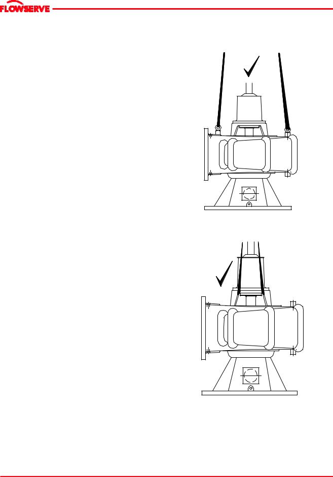
 To avoid distortion, the pump unit should be lifted as shown in sections 2.3.1.
It is strongly recommended to lift the pump using appropriate equipments and proven procedures. It is strongly recommended to employ experts for the task to avoid injury or loss of life.
 A crane must be used for all pump sets in excess of 25 kg (55 lb). Fully trained personnel must carry out lifting, in accordance with local regulations.
2.3.1 Lifting of pump together with the suction elbow/nozzle
(only MNZ configuration is shown in this illustration)
Use stuffing box head and /or lifting eyes (if provided) on the casing for lifting. Make sure to balance the weight such that there is no tilting to any one side.
Page 10 of 47
MNV & MNZ USER INSTRUCTIONS ENGLISH 71569188 11/04
 ®
®
2.3.2 Lifting of driver
Use driver lifting lugs/ or follow driver manufacturer’s User Instructions.
 A crane must be used for all pump sets in excess of 25 kg (55 lb). Fully trained personnel must carry out lifting, in accordance with local regulations. The driver and pump weights to be noted before lifting is attempted.
2.4 Storage
 Store the pump in a clean, dry location away from vibration. Leave piping connection covers in place to keep dirt and other foreign material out of pump casing. Turn pump at intervals to prevent brinelling of the bearings and the seal faces (if fitted), from sticking.
2.4.1 Inspection before storage
a)Inspect the preservative coating/painted surfaces on the various parts. Touch up whereever necessary.
b)Inspect all covers over pump openings and piping connections. If found damaged, remove the covers and inspect interiors of the opening for any deposits of foreign materials or water.
c)If necessary, clean and preserve the interior parts as noted above to restore the parts to the "as shipped" condition. Replace covers and fasten securely.
2.4.2 Short term storage (less than 6 months)
When it is necessary to store a pump for a short time before it can be installed, place it in a dry location and protect it thoroughly from moisture.
When protective flanges are bolted to the suction and discharge nozzles at the factory, they should not be removed. Protect the bearings and the shaft against moisture, dirt, or other foreign matter. To prevent rusting in or seizing, lubricate the unit; see Section 5.2, Pump Lubricants. Rotate the pump shaft a minimum of 5 revolutions every two weeks to keep the bearings coated with lubricant and to minimize the effects of brinelling.
 MNV and MNZ standard pumps are grease lubricated. Oil lubricated anti-friction bearings are factory lubricated to prevent rusting for a short period of time only. It is important to fill the recommended oil lubricant to proper level immediately upon receiving the equipment.
2.4.3 Long term storage (6 months and over)
 More thorough precautions are required if the pump is scheduled to be stored for an extended period of time. Contact Flowserve before long-term storage is attempted for specific storage requirements and warranty information.
The following is a general procedure and could vary depending upon the pump design and specific application.
 The storage area should be a clean and dry. The storage location not be subjected to rapid changes in temperature, light (no direct lighting) or humidity, and relatively free of ground transmitted vibration due to heavy construction and/or machinery.
A temperature range of 5 o to 50 oC ( 40 o to 120o F) with non-condensing humidity is recommended.
a)Drain fluid from the pump, rotate the pump rotor once in the proper direction and blow the liquid end dry with air.
b)Coat the interior surfaces of the liquid end with rust inhibitor by brushing, spraying or fogging. Rotate the pump shaft one turn in the proper direction while coating.
c)Remove the packing and seal cage from the stuffing box to prevent corrosion due to condensation. Coat the interior machined surfaces of stuffing box with a rust inhibitor. This step may be omitted if the pumps are stored prior to initial use.
d)For grease lubricated bearing frames, fill the cavity between the bearing covers and bearings with a good grade of NGLI No. 2 lithium base grease to prevent contamination of the bearings. Ensure the bearings are thoroughly packed with grease. Lubrication quality and quantity must be checked every six months and replaced or replenished as necessary.
e)Coat all threaded openings with rust inhibitor and plug. Coat machined surfaces of exposed flanges with rust inhibitor and then cover with fiberboard or wood flange covers. Desiccant bags should be secured to the covers prior to putting them in place and must not contact metal surfaces.
f)Coat exposed, unpainted, and machined surfaces with a rust inhibitor.
Page 11 of 47

MNV & MNZ USER INSTRUCTIONS ENGLISH 71569188 11/04
 ®
®
g)Cover openings in the stuffing box head between the casing and bearing frame with plastic, taped in place, to prevent entrance of contaminants into the stuffing box and line bearing area.
h)Cover the entire pump with a clear plastic sheet for protection from dust, dirt moisture, etc. and to allow for visual inspection. The cover should be open near the top to allow for ventilation.
i)Rotate the pump shaft a minimum of 5 revolutions every two weeks to keep the bearings coated with lubricant and to minimize the effects of brinelling.
j)Refer to the vendors instruction manuals for extended storage procedure for motors, controls, coupling, etc.,
k)Prior to start up or installation, an Flowserve representative should be hired to inspect all equipment to determine if any damage or deterioration of parts has occurred and that the equipment is in "as shipped" condition.
2.5 Recycling and end of product life
At the end of the service life of the product or its parts, the relevant materials and parts should be recycled or disposed of using an environmentally acceptable method and local regulations. If the product contains substances that are harmful to the environment, these should be removed and disposed of in accordance with current regulations. This also includes the liquids and or gases that may be used in the "seal system" or other utilities.


 Make sure that hazardous substances are disposed of safely and that the correct personal protective equipment is used. The safety specifications must be in accordance with the current regulations at all times.
3 DESCRIPTION
The MNV/MNZ type pumps are single stage, volute type, dry pit, centrifugal pumps designed for handling sewage, storm water, dry dock and industrial waste applications with end suction side discharge mix flow non-clog design.
It should be noted that unscreened raw sewage may introduce some chances of clogging and therefore clogging may be totally avoided, if appropriate level of screening is applied.
∙Pump type MNV (with the suction elbow)
∙Pump type MNZ (with the suction nozzle)
These are end suction side discharge mix flow nonclog pump. The information contained in this book covers long shafted pumps where the pump and driver are installed separately connected by one or multiple shafting using universal joints (some exceptional cases may have rigid or geared couplings). Type MNV is fitted with a suction elbow and MNZ with a suction nozzle.
Page 12 of 47

MNV & MNZ USER INSTRUCTIONS ENGLISH 71569188 11/04
 ®
®
3.1 Nozzle configurations
The MNV and MNZ pumps are configured with various nozzle positions, designated A-H as shown (Example: for counter clock-wise rotation).
A B C
3.1.1 Long shafting with U-joints.
(Example shown is MNZ pump assembly).
 Shaft guards are supplied if ordered. It is the responsibility of the operators of drive shaft and universal joints to provide and install guards or safety devices, which may be required by recognized safety standards.
GUARD
D E F
U SHAFTING
 TUBING
G H
SHAFT
GUARD 
Page 13 of 47

MNV & MNZ USER INSTRUCTIONS ENGLISH 71569188 11/04
 ®
®
3.2 Name nomenclature
The pump size will be engraved on the nameplate typically as below:
24-MNV/MNZ-47
Nominal discharge branch size.
Type/Configuration – see sec. 3.0.
Nominal impeller diameter. (Size in inches only)
The typical nomenclature above is the general guide to the MNV/MNZ configuration description. Identify the actual pump size and serial number from the pump nameplate. Check that this agrees with the applicable certification provided.
3.3 Design of major parts
3.3.1 Pump casing & stuffing box head
The pump casing with its integrally cast discharge nozzle is of the volute type. It is machined to provide a rabbet fit for the stuffing box head and suction head. The heads are removable and are bolted to and centered in the casing. The casing and suction head are each provided with one hand hole for inspection and cleaning of the pump without dismantling. The pump has its main casing gasket axial to the shaft allowing maintenance to the rotating element by separating the impeller assembly from the casing. Suction and discharge branches remain undisturbed
3.3.2 Impeller and wearing rings
The impeller is a solids handling type capable of passing trash and solids of limited size. The impeller hub is keyed to the shaft and held in position by an impeller nut which is set screwed to the impeller to prevent its backing off. A pair of replaceable wearing rings (optional) between the rotating impeller and the stationary suction head are provided for impeller wear resistance.
3.3.2.1 Impeller and wearing ring arrangement
IMPELLER
IMPELLER |
WEARING RING |
SUCTION HEAD
WEARING RING
 SUCTION HEAD
3.3.3 Shaft and shaft sleeve
The pump shaft is sized to transmit the rated loads encountered with liberal safety factors, and is accurately machined over its full length. Generous fillets are used to minimize stress concentrations. It is protected from wear at the stuffing box by a removable shaft sleeve.
3.3.4 Pump bearings and lubrication
MNV & MNZ pumps are equipped with anti-friction bearings of the tapered roller type. The line and thrust bearings are arranged in opposed mounting and can be furnished with grease as standard and custom built oil lubricated pumps.
3.3.5 Bearing housing
Bearings are mounted in a removable cast iron bearing frame. The frame casting offers solid support and location to the bearings and two grease nipples enable grease lubricated bearings to be replenished between major service intervals.
3.3.6 Stuffing box housing
The stuffing box housing cast integrally with the back head and has designed number of sealing options. For applications requiring Mechanical Seals refer to the Mechanical Seal Manufacturer's instructions.
Packing within the pump stuffing box seals the pump against leakage along the shaft at the point where it passes through the stuffing box. It should be packed with rings of braided, non-asbestos packing and a seal cage. It is equipped with a split removable packing gland.
Page 14 of 47
MNV & MNZ USER INSTRUCTIONS ENGLISH 71569188 11/04
 ®
®
The number of packing rings list is provided in section 6.1.8.1. Place two rings of packing below the seal cage and the remaining rings above the seal cage.
PUMP SHAFT
PACKING GLAND |
|
|
SEAL WATER |
|
|
CONNECTION |
|
|
SEAL CAGE |
|
|
PACKING |
STUFFING BOX |
|
HEAD |
||
|
||
SHAFT SLEEVE |
|
|
|
IMPELLER |
3.3.9 Intermediate shafting
Steel flexible shafting with universal joint couplings is usually used with MNV/MNZ pump installations. For operating instructions, refer to the U shaft manufacturer's User Instructions. See below for illustrations of driver and intermediate U-joint shafting.
 The stuffing box is not packed when the pump is shipped
A water supply of approximately 0.113 to 0.227 m3/h (0.5 to 1.0 gpm) is to be introduced to the seal water connection to provide for packing lubrication and sealing. A steady "trickle" of water from the stuffing box will indicate proper adjustment. The sealing water supply pressure should be 0.35 to 0.69 bar (5 to 10 psi) above the pump discharge pressure. When grease sealing is used, a similar grease pressure should be maintained. A slight leakage of liquid from the stuffing box is to be expected and the gland MUST NOT be tightened to the point of stopping the leakage.
3.3.7 Shaft seal
The mechanical seal(s) attached to the pump shaft seals the pumped liquid from the environment. Gland packing may be fitted as an option. See section 6.1.9 for mechanical seal maintenance information.
3.3.8 Driver
The driver is normally an electric motor. Different drive configurations may be fitted such as internal combustion engines, turbines, hydraulic motors etc., driving via couplings, belts, gearboxes, drive shafts. All metal flexible couplings are normally used for connecting pump and drive shafts. For operating instructions, refer to the coupling manufacturer's User Instructions.
3.3.10 Accessories
Accessories may be fitted when specified by the customer
3.4 Performance and operating limits
This product has been selected to meet the specifications of your purchase order. See section 1.5.
The following data is included as additional information to help with your installation. It is typical, and factors such as temperature, materials, and seal type may influence this data. If required, a definitive statement for your particular application can be obtained from Flowserve.
3.4.1 Operating limits
Pumped liquid temperature |
5 ºC (40 ºF) to +80 ºC (176 ºF) |
limits* |
|
Maximum ambient |
5 ºC (40 ºF) to +40 ºC (104 ºF) |
temperature* |
|
Maximum pump speed |
refer to the nameplate |
*Subject to written agreement from Flowserve. Special designs and materials may be available for pumps operating above and below these specified limits. Contact Flowserve for upgrade options available for your specific application.
3.4.2 Pump and impeller data
Details of impeller diameter (trim), wearing ring diameter, are normally provided with the pump along with the test curve data. If not found with the pump, please contact Flowserve representative.
Page 15 of 47
 Loading...