


|
USER INSTRUCTIONS |
Automax XCL/XML UltraSwitch™ |
Installation |
Switchbox |
Operation |
FCD AXENIM0120-13-A4 - (02/15) |
Maintenance |
|
|
Experience In Motion

Automax XCL/XML Switch Box User Instructions FCD AXENIM0120-13-A4 02/15
Contents
1 |
Introduction |
3 |
|
|
|
|
|
2 |
Installation |
3 |
|
|
|
|
|
|
2.1 |
Mounting to Actuator |
3 |
|
|
|
|
|
2.2 |
Wiring Instructions |
3 |
|
|
|
|
|
2.3 |
Special Hazardous Location Instructions |
3 |
|
|
|
|
3 |
Configuring the Unit |
4 |
|
|
|
|
|
|
3.1 |
Adjusting Limit Switches |
4 |
|
|
|
|
|
3.2 |
Cam Fine Adjustment |
5 |
|
|
|
|
|
3.3 |
Adjusting UltraDome Position Indicator |
5 |
|
|
|
|
|
3.4 |
Calibrating 4-20 mA Transmitter |
5 |
|
|
|
|
4 |
Specifications |
6 |
|
|
|
|
|
|
4.1 |
Switch Option Specifications |
6 |
|
|
|
|
|
4.2 |
Analog Feedback Option Specifications |
7 |
|
|
|
|
5 |
Hazardous Location Approvals |
7 |
|
|
|
||
6 Product Nomenclature |
8 |
||
|
|
|
|
7 |
Materials |
10 |
|
|
|
||
8 Dimensions |
10 |
||
|
|
|
|
|
8.1 Max Safe Gaps |
10 |
|
|
|
|
|
|
8.2 |
Drawings |
11 |
|
|
|
|
2

Automax XCL/XML Switch Box User Instructions FCD AXENIM0120-13-A4 02/15
1 Introduction
Automax UltraSwitch™ limit switch enclosures provide local and remote position indication for automated valves. They generally feature a visual indicator with “red=closed” and “green=open” for intuitive local position determination. The UltraSwitch is available with a number
of limit switch options for remote indication in a variety of electrical applications. The device may also be used as a junction box for direct installation of solenoid valves.
2 Installation
2.1 Mounting to Actuator
UltraSwitches may be installed to valves or valve actuators with a variety of mounting hardware. For best results, specify the NAMUR shaft option and NAMUR mounting hardware when installing to NAMUR compliant actuator. These options allow direct coupling to actuators without the need to use additional mounting kits, reducing dead band.
Simply bolt the bracket to the actuator and bolt the UltraSwitch to the bracket, leaving the bolts finger tight. For NAMUR applications, the UltraSwitch shaft features an integral alignment pin. This pin must engage the tapped hole in the actuator shaft. For non-NAMUR applications, make sure to properly install a coupler between the UltraSwitch and actuator. Once the UltraSwitch is installed with fasteners loosely tightened, stroke the actuator two or three times to align the bracket, then tighten all fasteners.
2.2 Wiring Instructions
UltraSwitch enclosures feature pre-wired switches. All user connections are made at a numbered terminal strip. Both external bonding and internal grounding locations have been provided for use in installation. A wiring diagram is located inside the cover and indicates which terminal numbers correspond to switch contacts: normally open, normally closed, common, etc. Simply follow the wiring diagram and electric code to connect switches to your system.
For field wiring: ensure that any excess wire lengths or loops are routed away from any moving parts and are short enough, or secured to ensure a ¼” clearance between the wire and the inside surface of the switch box cover.
NOTE: For all magnetically-tripped proximity switches, the top switch (top and third switches for 4-switch versions) should only be used to indicate the clockwise position: the bottom switch (second and fourth switches for 4-switch versions) should only be used to indicate the counter-clockwise position. Any deviation from these settings may result in erratic indication.
Solenoids may also be wired through the UltraSwitch enclosure. At least two auxiliary terminals are included as standard.
A ground screw is also included. Simply wire the solenoid to auxiliary terminals, then connect power leads to the opposite terminal side. Be sure to properly ground the solenoid at provided ground terminal. UltraSwitch XCL series enclosures include two ¾” NPT conduit entries and the XML series includes two M25x1.5 conduit entries. Installation shall be per National Electric Code, local codes, and manufacturers’ instructions.
2.3 Special Hazardous Location Instructions
Connecting cables must be rated for ambient temperatures above 100°C (212°F). Therefore select appropriately-rated cable.
a WARNING: To prevent ignition of hazardous atmospheres, conduit runs must have sealing fitting located within 18 inches of the enclosure to meet NEC regulations. See Solenoid nameplate for additional electrical rating.
For ATEX and IECEx installations, an appropriately-rated Cable Gland is required.
In all cases, environmental seals must be used to protect against ingress of water through the conduit.
Any unused conduit entry must have a suitably-rated blanking element.
Modification of the product is not permitted. If equipment is modified, then the equipment can no longer be used in explosive atmospheres.
a CAUTION:
•Substitution of components may impair suitability for Zone 2 Increased Safety.
•Do not disconnect equipment unless power has been switched off or the area is non-hazardous. To prevent ignition of hazardous atmospheres, keep unit tightly closed while circuits are live.
•Due to the risk of static electricity, cleaning this housing by rubbing should be done in a non-hazardous area. In this instance, the unit must first be removed and then taken to a non-hazardous area.
•To avoid the risk of potential electrostatic charging hazard, clean only with a damp cloth. All grounding and bonding installation requirements must be in Automaxance with the governing hazardous location standards corresponding to the specific environment and application the device will be installed in.
•All installation, inspection, and maintenance of the equipment must be performed by trained and authorized personnel. In addition, for equipment certified for use in hazardous areas, all installation, inspection, maintenance and repair must be done by trained personnel.
•Only Flowserve replacement parts must be used in order to not invalidate certification.
• Modification of the product including label and markings is not |
3 |
permitted. |
|
flowserve.com
Automax XCL/XML Switch Box User Instructions FCD AXENIM0120-13-A4 02/15
Special Conditions For Safe Use
(see section 8.1 with max safe gaps)
a CAUTION (specific for different certificates):
cCSAus EX:
aCAUTION: To prevent ignition of hazardous atmospheres, keep unit tightly closed while circuits are live. Disconnect supply circuit before opening.
aAVERTISSEMENT: ouvrir le circuit avant d’enlever le couvercle bien ferme’ lorsque les circuitssont sous tension.
INMETRO Ex d:
“ATENÇÃO-NÃO ABRA QUANDO ENERGIZADO”
“ATENÇÃO-RISCO POTENCIAL DE CARGA ELECTROSTÁTICA - LIMPE SOMENTE COM UM PANO ÚMIDO”
“ATENÇÃO-UTILIZE CABOS APROPIADOS PARA A TEMPERATURADE 110 ºC”
3 Configuring the Unit
cCSAus NI:
aWARNING: Explosion hazard - substitution of components may impair suitability for class i, division 2.
a AVERTISSEMENT: risque d’explosion - la substitution de composants peut rendre ce material inacceptable pour les emplacements de class i, division 2.
aWARNING: Explosion hazard - do not disconnect equipment unless power has been switched off or the area is non-hazardous.
aAVERTISSEMENT: ouvrir le circuit avant d’enlever le couvercle bien ferme lorsque les circuits sont sous tension.
cCSAus IS:
aWARNING: Substitution of components may impair intrinsic safety.
aWARNING: To prevent ignition of flammable or combustible atmospheres, disconnect power before servicing. Refer to control drawing x00525c for entity parameters and installation.
ATEX/IECEx/KOSHA Ex d:
a WARNING: Potential electrostatic charging hazard, clean only with a damp cloth. Danger of propagating discharge.
aCAUTION: To prevent ignition of hazardous atmospheres, keep unit tight while circuits are live. Disconnect supply circuit before opening.
aAVERTISSEMENT: ouvrir le circuit avant d’enlever le couvercle bien ferme’ lorsque les circuits sont sous tension.
aWARNING: Connecting cables must be rated for ambient temperatures above 100°C (212°F). Therefore select appropriately-rated cable.
4 a WARNING: To prevent ignition of hazardous atmospheres, conduit runs must have sealing fitting located within 18 inches of the enclosure. See nameplate for version with solenoid for additional electrical rating.
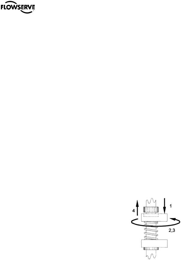
3.1 Adjusting Limit Switches
UltraSwitch enclosures feature quick-set cams which are used to trip the limit switches. These cams are easily adjusted without tools.
a CAUTION: Disconnect power before removing cover when installed in hazardous locations. Remove cover and set aside. Rotate actuator/valve to full clockwise (CW) position. Adjust cam(s) associated with CW as follows:
1.Push or pull cam against spring to disengage it from splines.
2.Rotate cam CW, breaking contact with switch (or moving magnet away from switch).
3.Continue rotating cam CW until switch trips.
4.Release cam and reengage it with splines.
5.Rotate actuator/valve to full counterclockwise (CCW) position. Adjust cam(s) associated with CCW as described insteps 1 through 4, except rotate cam(s) CCW.
NOTE: Factory setting is top switch = CW (closed), second switch = CCW (open), third switch = CW, and fourth switch = CCW.
 Loading...