


USER INSTRUCTIONS
LPS Pneumatic Heavy-Duty Actuator Series |
Installation |
Single Acting & Double Acting |
Operation |
FCD LFENIM0001-02-AQ |
Maintenance |
|
|
Experience In Motion

LPS Series Heavy-Duty Actuators FCD LFENIM0001-02-AQ – 5/15
Contents
1 |
Standard Information |
4 |
|
Using Flowserve Valves, Actuators and Accessories Correctly |
4 |
||
|
1.1 |
Terms Concerning Safety |
4 |
|
1.2 |
General Usage |
5 |
|
1.3 |
Protective Clothing |
5 |
|
1.4 |
Qualified Personnel |
5 |
|
1.5 |
Other Requirements for In-plant Installation |
6 |
|
1.6 |
Spare Parts |
6 |
|
1.7 |
Service/Repair |
6 |
|
1.8 |
Actuator Lifting and Handling |
6 |
|
1.9 |
Storage |
9 |
|
1.10 |
Valve and Actuator Variations |
10 |
|
1.11 |
Unpacking |
10 |
2 |
Installation Instructions |
11 |
|
|
2.1 |
Valve and Actuator Check |
11 |
|
2.2 |
Connection With Valve and Mounting Kit |
12 |
|
2.3 |
Travel-stop Bolts and Accessories |
13 |
|
2.4 |
Grounding System |
13 |
|
2.5 |
Initial Operation |
14 |
|
2.6 |
Fail Open and Fail Close Configuration |
15 |
3 |
Field Conversion |
16 |
|
|
Field Conversion From Fail CW to Fail CCW or Vice Versa (for Spring Return Actuators) |
16 |
|
|
3.1 |
Actuator Disassembled From the Valve |
16 |
|
3.2 |
Actuator Connected to the Valve (and the valve can be stroked) |
17 |
4 |
Maintenance Instructions |
19 |
|
|
4.1 |
General Disassembly Instructions |
20 |
|
4.2 |
Spring Container Maintenance |
20 |
|
4.3 |
Pneumatic Cylinder Maintenance |
22 |
|
4.4 |
Scotch Yoke Housing Maintenance |
23 |
|
4.5 |
Spare Parts |
24 |
5 |
Troubleshooting |
25 |
|
6 |
Disposal of Decommissioned Actuators |
27 |
|
7 |
Annex |
|
28 |
2

LPS Series Heavy-Duty Actuators FCD LFENIM0001-02-AQ – 5/15
Figures
Figure 1: Lifting Lug for Spring Can Lifting Only |
7 |
Figure 2: Correct Lifting of Pneumatic Single Acting Actuator |
7 |
Figure 3: Use of Eyebolt for the Scotch Yoke Housing Cover |
7 |
Figure 4: Vent Valve Correct Position |
7 |
Figure 5: Lifting Lug on the Pneumatic Cylinder |
8 |
Figure 6: Correct Lifting of LPS-15, LPS-20 and LPS-25 Pneumatic Single Acting Actuator Models |
8 |
Figure 7: Single Acting Actuator Center of Gravity Position and Lifting Arrangement |
8 |
Figure 8: Double Acting Actuator Center of Gravity Position and Lifting Arrangement |
9 |
Figure 9: Actuator’s Safe Packed Position on Wooden Pallet |
9 |
Figure 10: Fail CW Plate, According to EN 15714-3 Standard |
11 |
Figure 11: Nameplate Sample |
11 |
Figure 12: Standard Nameplate Position |
11 |
Figure 13: Air Supply Plate |
11 |
Figure 14: Grounding Kit Detail |
13 |
Figure 15: Grounding Kit Assembled |
13 |
Figure 16: Grounding Kit – Exploded Lettered View |
14 |
Figure 17: Single Acting Actuator Configuration: Fail Close – Fail Clockwise |
15 |
Figure 18: Single Acting Actuator Configuration: Fail Open – Fail Counter Clockwise |
15 |
Figure 19: Double Acting Actuator Configuration – Close Position |
15 |
Figure 20: Double Acting Actuator Configuration – Open Position |
15 |
Figure 21: Single Acting LPS With Valve |
15 |
Figure 22: Double Acting LPS With Valve |
15 |
Figure 23: Single Acting Actuator |
20 |
Figure 24: Spring Can Exploded View |
21 |
Figure 25: Exploded View of Pneumatic Cylinder |
22 |
Figure 26: Exploded View of Housing |
23 |
Figure 27: Exploded View of Assembling Kit |
23 |
Figure 28: LPS Model Selection Table |
28 |
Figure 29: Weight Selection Table – Single Acting and Double Acting Versions |
28 |
Figure 30: Mounting Interface Dimensions |
30 |
Figure 31: Actuator Orientation/Installation |
31 |
Tables
Table 1: Spare Parts List for Standard ON/OFF Applications |
24 |
Table 2: Tightening Torques for Screws Without Lubricant (Tie Rods Excluded) |
29 |
Table 3: Tightening Torque Table for Standard Cylinder (Without Ped Certification) |
29 |
Table 4: Tightening Torque Table for PED Certified Cylinder Tie Rods Without Lubricant |
29 |
3
flowserve.com

LPS Series Heavy-Duty Actuators FCD LFENIM0001-02-AQ – 5/15
1 Standard Information
Using Flowserve Valves, Actuators and Accessories Correctly
The following instructions are designed to assist in unpacking, installing and performing maintenance as required on the LPS Actuator Series. Product users and maintenance personnel should thoroughly review this bulletin prior to installing, operating or performing any maintenance.
In most cases Flowserve actuators and accessories are designed for specific applications with regard to medium, pressure and temperature. For this reason they should not be used in other applications without first contacting the manufacturer.
1.1 Terms Concerning Safety
The safety terms DANGER, WARNING, CAUTION and NOTE are used in these instructions to highlight particular dangers and/or to provide additional information on aspects that may not be readily apparent.
c |
DANGER: indicates that death, severe personal injury and/or substantial property damage will occur if proper |
|
precautions are not taken. |
aWARNING: indicates that death, severe personal injury and/or substantial property damage can occur if proper precautions are not taken.
aCAUTION: indicates that minor personal injury and/or property damage can occur if proper precautions are not taken.
NOTE: indicates and provides additional technical information, which may not be very obvious, even to qualified personnel.
Compliance with other, not particularly emphasized notes, with regard to transport, assembly, operation and maintenance and with regard to technical documentation (e.g., in the operating instruction, product documentation or on the product itself) is essential, in order to avoid faults, which in themselves might directly or indirectly cause severe personal injury or property damage.
4

LPS Series Heavy-Duty Actuators FCD LFENIM0001-02-AQ – 5/15
1.2 General Usage
To prolong actuator life, use only clean, dry pneumatic supply fluids. Lubricated fluids are not required for LPS actuators. Pay attention to follow positioner and other control prescriptions, regarding supply fluid instrument air.
The LPS actuator standard ambient temperature range is: -29°C to 100°C (-20°F to 212°F). Low temperature -60°C (-76°F) and High temperature 160°C (320°F) ranges (polar, cold, arid and tropical temperature requirements in accordance with IEC 60721) are available with different materials of construction. In any case, please refer to the temperature range located in the actuator nameplate.
NOTE: For PED certified applications the standard operating temperature range is -20°C to 100°C (-4°F to 212°F). For lower temperature applications the range can be extended to -40°C to +100°C (-40°F to 212°F) or -50°C to +100°C (-58°F to 212°F) with different materials of construction. In any case, please refer to the temperature range located in the actuator nameplate.
It is the end user’s responsibility to guarantee that the ambient temperature is in according with the actuator nameplate indications.
aWARNING: It is recommended not to exceed the minimum and maximum allowable temperatures indicated on the actuator nameplate. More factors like the valve and pipe temperatures, sun direct exposure and other environmental conditions shall be considered, not to exceed the temperature range.
aWARNING: It is recommended not to exceed the allowable pressure range of the supply fluids, as stated in the actuator nameplate. It is very important to make the standard maintenance at all safety components. In case of PED certified cylinders the value of design pressure of the cylinder is indicated on, specific and separate
nameplate: it is necessary to verify that the supply line to the actuator does not exceed the design pressure stated in the cylinder nameplate.
NOTE: The standard supply fluids are instrument air and nitrogen. Different types of fluids may be used only after Flowserve verification. In case of PED certified cylinders the type of fluid is indicated on the specific nameplate on the cylinder.
aWARNING: Only use the recommended type of fluid that is indicated on the nameplate (PED cylinders) and/or in the contract.
NOTE: The supply fluid must be properly filtered. In case of positioner and/or other components installed on the control panel, take care that the cleanliness, the filtration and the hydration of the supply fluid are in accordance with the requirements of these accessories indicated on their own maintenance and user manuals.
1.3 Protective Clothing
Flowserve products are often used in dangerous applications (e.g., extremely high pressures, flammable, combustible, toxic or corrosive media). When performing service, inspection or repair operations, always ensure that the valve and actuator are depressurized and that the valve has been cleaned and is free from harmful substances. In such cases pay particular attention to personal protection equipment (protective clothing, gloves, glasses, etc.).
1.4 Qualified Personnel
Only qualified personnel should perform installation, operation or maintenance activities. Qualified personnel are people who, on account of their training, experience, instruction and their knowledge of relevant standards, specifications, accident prevention regulations and operating conditions, have been authorized by those responsible for the safety of the plant to perform the necessary work and who can recognize and avoid possible dangers.
5
flowserve.com

LPS Series Heavy-Duty Actuators FCD LFENIM0001-02-AQ – 5/15
1.5 Other Requirements for In-plant Installation
• Pipelines must be correctly aligned to ensure that the valve is not fitted under tension.
• If not expressly agreed, fire protection is not supplied along with the acuator and it must be provided by the user.
1.6 Spare Parts
Use only Flowserve brand original spare parts. Flowserve cannot accept responsibility for any damages that occur from using spare parts or fastening materials from other manufacturers. If Flowserve products (especially sealing materials) have been in storage for long periods, check these for corrosion or deterioration before using these products. A table with the list of the main spare parts for standard ON/OFF applications with the interval times can be found in Paragraph 4.5 at Table 1.
1.7 Service/Repair
To avoid injury to personnel or damage to products, safety terms must be strictly adhered to. Modifying this product, substituting non-factory parts, or using maintenance procedures other than as outlined in this instruction could drastically affect performance and be hazardous to personnel and equipment, and may void existing warranties.
Between actuator and valve there are moving parts. To avoid injury, Flowserve provides pinch-point-protection in the form of cover plates, especially where side-mounted positioners are fitted. These protections are according to Machine Directive 2006/42/EC recommendations. If these plates are removed for inspection, service or repair special attention is required. After completing work the cover plates must be refitted.
In addition to the operating instructions and the obligatory accident prevention directives valid in the country of use, all recognized regulations for safety and good engineering practices must be followed.
aWARNING: Before products are returned to Flowserve for repair or service, Flowserve must be provided with a certificate which confirms that the product has been decontaminated and is clean. Flowserve will not accept deliveries if a certificate has not been provided (a form can be obtained from Flowserve).
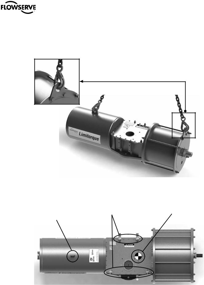
1.8 Actuator Lifting and Handling
Only Allen wrenches and hexagonal wrenches of the few sizes are required for the overall operations. The lifting equipment consists on commercial chains and slings of adequate dimensions.
In order to prevent damage to actuator accessories, before starting the lifting operations, ensure that the lifting tools, like chain and clevis hook, are in the correct position and don’t interfere with the control panel and related tubing.
aCAUTION: Lifting and handling of the actuator should be done by qualified personnel and in compliance with the laws and regulations in force.
aWARNING: The lifting lugs or eyebolts are appropriate for actuator lifting only. They are not designed to support the combined weight of the valve and actuator assembly together. During the lifting operations do not stand under the actuator. The actuator should be handled with appropriate lifting equipment. The weight of the actuator is reported on the packing slip and on the overall-dimensions drawing furnished with the documents accompanying the actuator.
For actuator weight, please, refer to Figure 29 in the Annex section. For the general actuator dimensions please refer to LPS technical bulletin LFENTB0001, available on www.flowserve.com.
6

LPS Series Heavy-Duty Actuators FCD LFENIM0001-02-AQ – 5/15
a WARNING: ONLY for LPS-30 model and larger sizes
Figure 1: Lifting Lug for
Spring Can Lifting Only
c |
DANGER: For lifting and handling, use the eyebolts on |
|
the housing. The eyebolt on the spring can is only for the |
|
mounting/dismounting steps or eventually for balancing |
|
the actuator. |
Figure 2: Correct Lifting of Pneumatic Single Acting Actuator
Figure 3: Use of Eyebolt for the Scotch Yoke |
Figure 4: Vent Valve Correct Position |
Housing Cover |
7 |
|
|
|
flowserve.com |
LPS Series Heavy-Duty Actuators FCD LFENIM0001-02-AQ – 5/15
a WARNING: ONLY for LPS-15, LPS-20 and LPS-25 model sizes
c |
DANGER: For lifting and handling, use the appropriate lifting lug located |
|
on the pneumatic cylinder and the lifting lug on the spring can. |
Figure 5: Lifting Lug on the
Pneumatic Cylinder
Figure 6: Correct Lifting of LPS-15, LPS-20 and LPS-25 Pneumatic Single Acting Actuator Models
Lifting Lug for Spring Can |
Eyebolts for Actuator Lifting |
Center of Mass |
and Actuator Balancing |
|
|
8 |
Figure 7: Single Acting Actuator Center of Gravity Position and Lifting Arrangement |

LPS Series Heavy-Duty Actuators FCD LFENIM0001-02-AQ – 5/15
Center of Mass
Eyebolts for
Actuator Lifting
Figure 8: Double Acting Actuator Center of Gravity Position and Lifting Arrangement
aWARNING: For lifting and handling use the appropriate lifting arrangement, as shown in Figure 2 and Figure 6. Do not lift the actuator with the valve assembled.
a WARNING: After transportation, inspect the components to look for any damage.
1.9 Storage
In many cases Flowserve products are manufactured from stainless steel. Products not manufactured from stainless steel are typically provided with an epoxy resin coating or with other painting systems as agreed with the customer. This means that Flowserve products are well protected from corrosion. Nevertheless, in order to maintain good working conditions and a good finish, until the actuator is installed in the plant, it is necessary to follow a few rules during the storage period:
1.9.1Flowserve products must be stored adequately in a clean, dry environment.
1.9.2Ensure that plastic caps are fitted to protect the pneumatic connections and the cable entries, to prevent the ingress of foreign materials. These caps should not be removed until the product is actually mounted into the system.
1.9.3If the storage is outdoors, or if long-term storage is necessary (more than four months), the plastic protection plugs must be replaced with metal plugs, because the plastic plugs are not weatherproof, whereas the metal ones guarantee weatherproof protection.
1.9.4The actuator must be placed on a wooden pallet, in order to not damage the coupling base and avoid the other surfaces resting on the ground.
In case of long-term storage (more than four months), additionally perform the following measures:
a.Coat the coupling parts (spool piece base, flanges, bushings, joints) with protective oil or grease.
b.If possible, blank off the spool piece base flange with a protection disk.
c.Provide a tarpaulin cover or some other means of protection, especially if the storage is outdoors.
d.It is important to periodically operate the actuator with filtered, dehydrated and lubricated air while in storage.
Figure 9: Actuator’s Safe Packed Position on Wooden Pallet |
9 |
|
flowserve.com

LPS Series Heavy-Duty Actuators FCD LFENIM0001-02-AQ – 5/15
1.10 Valve and Actuator Variations
These instructions cannot claim to cover all details of all possible product variations, nor can they provide information for every possible example of installation, operation or maintenance. If there are any uncertainties in this respect particularly in the event of missing product-related information, clarification must be obtained via the appropriate Flowserve sales office.
1.11 Unpacking
1.11.1Each delivery includes a packing slip. When unpacking, check all delivered actuators and accessories using this packing slip.
1.11.2Report transportation damage to the carrier immediately.
1.11.3In case of discrepancies, contact your nearest Flowserve location.
1.11.4If necessary, retouch minor damage to the paint coating which may have occurred during transport or storage.
NOTE: Ensure that the addendum “ATEX/PED/Machinery Directive Manual” accompanies this manual, when the actuator is under one (or more) of the following European Directives:
•2006/42/EC - Machinery Directive
•94/9/EC - ATEX Directive
•97/23/EC - PED Directive
If “ATEX/PED/Machinery Directive Manual” is not in your hands, contact Flowserve.
NOTE: When the actuator has SIL requirements according to IEC 61508, ensure that the “LPS Series Functional Safety Manual” accompanies this manual and is referred to for equipment usage.
10
 Loading...