


GESTRA Steam Systems
PA 46
PA 47
MPA 46
MPA 47
Installation Instructions 818447 00
Rapid Action Intermittent Valve for Removing Boiler Sludge PA 46, PA 47, MPA 46, MPA 47

Contents |
|
|
Page |
Important Notes |
|
Usage for the intended purpose............................................................................................................... |
4 |
Safety note.............................................................................................................................................. |
4 |
Danger.................................................................................................................................................... |
4 |
Classification pursuant to Article 9 of the Pressure Equipment Directive (PED) 97/23/EC.......................... |
5 |
Classification pursuant to Annex 1 of ATEX Directive 94/9/EC................................................................... |
5 |
Explanatory Notes |
|
Scope of supply....................................................................................................................................... |
6 |
Description.............................................................................................................................................. |
7 |
Function.................................................................................................................................................. |
7 |
Technical Data |
|
End connection........................................................................................................................................ |
8 |
Pressure ratings...................................................................................................................................... |
8 |
Materials................................................................................................................................................. |
8 |
Pressure & temperature ratings............................................................................................................... |
8 |
Corrosion resistance................................................................................................................................ |
9 |
Sizing...................................................................................................................................................... |
9 |
Name plate/ marking............................................................................................................................... |
9 |
Capacity chart PA 46, PA 47, MPA 46, MPA 47....................................................................................... |
10 |
Control pressure chart MPA 46, MPA 47................................................................................................ |
11 |
Design |
|
PA 46, PA 47......................................................................................................................................... |
12 |
MPA 46, MPA 47.................................................................................................................................... |
13 |
Key........................................................................................................................................................ |
14 |
Installation |
|
PA 46, PA 47, MPA 46, MPA 47.............................................................................................................. |
15 |
Flanged design...................................................................................................................................... |
15 |
Socket-weld design............................................................................................................................... |
15 |
Butt-weld design .................................................................................................................................. |
16 |
Heat treatment of welds ....................................................................................................................... |
16 |
Mounting of hand lever ......................................................................................................................... |
16 |
Commissioning |
|
PA 46, PA 47, MPA 46, MPA 47 ............................................................................................................. |
16 |
Operation |
|
Duration and frequency of intermittent boiler blowdown........................................................................ |
17 |

Contents - continued - |
|
|
Page |
Emergency operation MPA 46, MPA 47 |
|
Danger.................................................................................................................................................. |
17 |
Fit hand lever for emergency operation.................................................................................................. |
17 |
Maintenance |
|
Danger.................................................................................................................................................. |
17 |
Replacing stuffing box PA 46, PA 47...................................................................................................... |
18 |
Replacing stuffing box, valve seat and valve plug PA 46, PA 47.............................................................. |
19 |
Replacing stuffing box MPA 46, MPA 47................................................................................................ |
20 |
Replacing stuffing box, valve seat and valve plug MPA 46, MPA 47........................................................ |
21 |
Retightening stuffing box....................................................................................................................... |
22 |
Replacing control membrane in diaphragm actuator MPA 46, MPA 47................................................... |
22 |
Torques................................................................................................................................................. |
23 |
Tools..................................................................................................................................................... |
23 |
Single parts of stuffing box, valve plug, valve seat................................................................................. |
24 |
Mounting/removing valve seat............................................................................................................... |
25 |
Mounting/removing control membrane.................................................................................................. |
26 |
Key........................................................................................................................................................ |
27 |
Retrofitting |
|
Danger.................................................................................................................................................. |
27 |
Mounting diaphragm actuator............................................................................................................... |
27 |
Mounting forkhead................................................................................................................................ |
28 |
Tools..................................................................................................................................................... |
28 |
Torques................................................................................................................................................. |
28 |
Spare Parts |
|
Spare parts list...................................................................................................................................... |
29 |
Parts for retrofitting |
|
List of parts for retrofitting..................................................................................................................... |
30 |
Decommissioning |
|
Danger.................................................................................................................................................. |
30 |
Disposal................................................................................................................................................ |
30 |
Annex |
|
Declaration of Conformity...................................................................................................................... |
31 |

Important Notes
Usage for the intended purpose
PA 46, PA 47, MPA 46, MPA 47:
Use the rapid-action intermittent valves*) only for removing boiler water containing accumulated non-metallic sediments from steam boilers within the admissible pressure und temperature ratings.
Use only compressed air (at room temperature) or pressurized water (at room temperature) as control fluid for the GESTRA diaphragm actuator in accordance with the specified pressure/temperature ratings.
Application in potentially explosive atmospheres as classified according to Annex I of ATEX Directive 94/9/EC.
*) Please note:
In British English an intermittent valve for removing boiler sludge is referred to as “(intermittent) bottom blowdown valve”.
In American English the term “(intermittently operating) blowoff valve” is used, but only in conjunction with a slow-opening valve (ASME code).
Safety Note
The equipment must only be installed and commissioned by qualified and competent staff. Retrofitting and maintenance work must only be performed by qualified staff
who – through adequate training – have achieved a recognised level of competence.
Danger
The valve is under pressure during operation.
When loosening flanged connections, sealing plugs or stuffing boxes, hot water and steam may escape.
Before carrying out installation and maintenance work make sure the system is depressurized.
Isolate the valve from both upstream and downstream pressure. Depressurize control lines!
The valve becomes hot during operation.
This presents the risk of severe burns to hands and arms.
Before carrying out installation and maintenance work make sure that the valve is cold.
Risk of severe burns and scalds to the whole body!
Before carrying out any maintenance work on the valve or loosening flanged connections, stuffing box unions or sealing plugs make sure that all connected lines are depressurized (zero bar) and cooled down to room temperature (20 °C).
During operation moving internals can pinch one’s hands or fingers, causing severe injuries. Do not touch the valve during operation! The intermittent valves for removing boiler sludge MPA 46, MPA 47 are time controlled and can open and close abruptly.
Sharp edges on internals present a danger of cuts to hands. Always wear industrial gloves when replacing the packing, valve seat or valve plug!
Important Notes - continued -
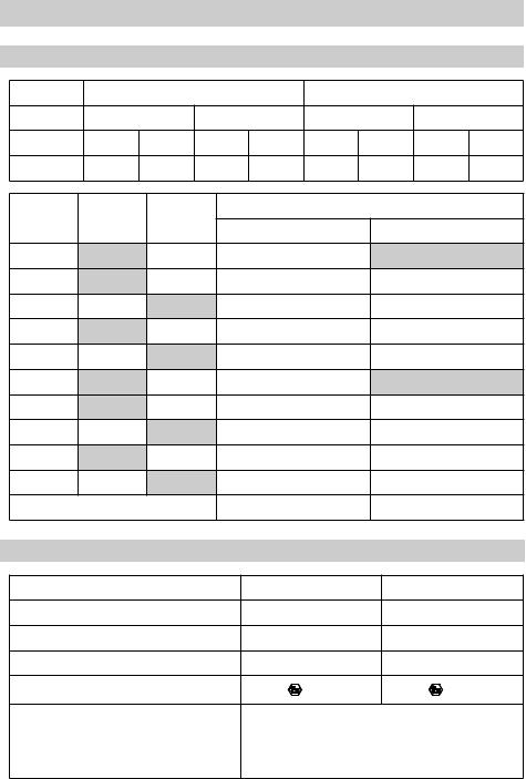
Classification pursuant to Article 9 of the Pressure Equipment Directive (PED) 97/23/EC
Type |
|
PA 46, PA 47 |
|
|
MPA 46, MPA 47 |
|
||
Fluid |
Gas, steam |
|
Liquid |
Gas, steam |
Liquid |
|
||
Fluid group |
1 |
2 |
1 |
2 |
1 |
2 |
1 |
2 |
Application |
no |
yes |
no |
yes |
no |
yes |
no |
yes |
Type |
PN |
CLASS |
|
|
Nominal size DN |
|
|
|
Exception pursuant to article 3.3 |
|
Category I |
|
|||||
|
|
|
|
|
||||
MPA 46 |
|
CL 150 |
|
20, 25, 32, 40, 50 |
|
|
|
|
MPA 46 |
|
CL 300 |
|
20, 25, 32 |
|
|
40, 50 |
|
MPA 46 |
PN 40 |
|
|
20, 25, 32 |
|
|
40, 50 |
|
MPA 47 |
|
CL 400 |
|
25 |
|
|
40, 50 |
|
MPA 47 |
PN 63 |
|
|
25 |
|
|
40, 50 |
|
PA 46 |
|
CL 150 |
|
20, 25, 32, 40, 50 |
|
|
|
|
PA 46 |
|
CL 300 |
|
20, 25, 32 |
|
|
40, 50 |
|
PA 46 |
PN 40 |
|
|
20, 25, 32 |
|
|
40, 50 |
|
PA 47 |
|
CL 400 |
|
25 |
|
|
40, 50 |
|
PA 47 |
PN 63 |
|
|
25 |
|
|
40, 50 |
|
|
CE Marking |
|
|
no |
|
|
0525 |
|
Classification pursuant to Annex 1 of ATEX Directive 94/9/EC |
|
|
|
|||||
Type |
|
|
|
PA 46, PA 47 |
|
MPA 46, MPA 47 |
||
Equipment group |
|
|
II |
|
|
II |
|
|
Equipment category |
|
|
2 |
|
|
2 |
|
|
Potentially explosive atmosphere (1999/92/EC) |
1, 2, 21, 22 |
|
1, 2, 21, 22 |
|
||||
CE Marking / EX Marking |
|
|
II 2 G/D c X |
|
II 2 G/D c X |
|||
The equipment itself does not generate inadmissibly high
Marking “X” surface temperatures. The user must make sure that the operating fluid does not generate inadmissibly high surface
temperatures.

Explanatory Notes
Scope of supply
PA 46
1 Intermittent valve for removing boiler sludge PA 46
1 Hand lever
1 Installation manual
PA 47
1 Intermittent valve for removing boiler sludge PA 47
1 Hand lever
1 Installation manual
MPA 46
1 Intermittent valve for removing boiler sludge MPA 46
1 Installation manual
MPA 47
1 Intermittent valve for removing boiler sludge MPA 47
1 Installation manual
Retrofitting kit for PA 46, PA 47
1 Diaphragm actuator
1 Spacer disc
1 Installation manual
Hand lever for emergency operation
1 Hand lever for emergency operation
1 Forkhead G 10 x 20, DIN 71752
1 Hexagon-head cap screw
Spare Parts
1 Kit according to spare parts list (see page 29)

Explanatory Notes - continued -
Description
Intermittent valves for manual or automatic and programme-controlled removing of boiler sludge from land or marine installations, particularly if these installations are operated without constant supervision in accordance with TRD 604. Sludge sediments, which are accumulated precipitates from boiler water that settle at the bottom of the boiler, will be removed from the steam boiler with the the aid of valves PA and MPA. These valves give the boiler a short blow at regular intervals, thereby discharging accumulated sludge and sediments.
■PA 46 and PA 47 are designed for manual operation (diaphragm actuator can be retrofitted).
■MPA 46 and MPA 47 feature a diaphragm actuator for compressed air or pressurized water.
Function
The intermittent valves for removing boiler sludge PA 46 and PA 47 are openend by means of a hand lever. A pressure pin forces the spring-loaded valve plug out of the valve seat. The large crosssectional area of the orifice creates a suction effect, giving a short-term high water flow which will discharge the precipitated sludge and sediments and - if installed - move them to a mixing cooler (= blowdown receiver). The intermittent valve for removing boiler sludge must be completely opened for about 2 seconds with the aid of the hand lever in order to give the boiler a short and highly effective blow.
The intermittent valves for removing boiler sludge MPA 46 and MPA 47 are openend by the diaphragm actuator. The guide pin of the diaphragm actuator acts upon the pressure pin, which in turn forces the spring-loaded valve plug out of the valve seat. The large cross-sectional area of the orifice creates a suction effect, giving a short-term high water flow which will discharge the precipitated sludge and sediments and - if installed - move them to a mixing cooler (= blowdown receiver). Compressed air (at room temperature) or pressurized water (at room temperature) can be used as control fluid for the diaphragm actuator in accordance with the specified pressure and temperature ratings (see diagram on page 11).
The duration of the bottom blowdown, i. e. the time when the valve is open, should be approx.
2 seconds. The time period when the valve remains closed and hence the frequency of the bottom blowdown must be established as a function of the size and capacity of the steam boiler. We recommend that approx. 10 per cent of the total amount of boiler water to be removed is discharged via the intermittent valve for removing boiler sludge.
The duration and frequency of the bottom blowdown must be established individually by the user as a function of the size and capacity of the steam boiler, the boiler water quality and the corresponding load.

Technical Data
Connections
Type |
|
|
Standard |
|
|
On request |
|
||
|
|
|
|
|
|
Flanges to Class 150, 300 |
|
||
(M)PA 46 |
|
Flanges to DIN, PN 40 |
|
Butt-weld ends for DIN and ASME pipes |
|||||
|
|
|
|
|
Socket-weld ends for DIN and ASME pipes |
||||
|
|
|
|
|
|
|
|
||
|
|
|
|
|
|
Flanges to Class 400 |
|
||
(M)PA 47 |
|
Flanges to DIN, PN 63 |
|
Butt-weld ends for DIN and ASME pipes |
|||||
|
|
|
|
|
Socket-weld ends for DIN and ASME pipes |
||||
|
|
|
|
|
|
|
|
|
|
|
|
|
|
|
|
|
|
|
|
Pressure Ratings |
|
|
|
|
|||||
(M)PA 46 |
|
|
|
EN – PN 40 |
|
Class 150, 300 |
|||
|
|
|
|
|
|
|
|
|
|
(M)PA 47 |
|
|
|
EN – PN 63 |
|
Class 400 |
|
||
|
|
|
|
|
|
|
|
|
|
|
|
|
|
|
|
|
|
|
|
Materials |
|
|
|
|
|
|
|
|
|
|
|
|
|
|
|
|
|
|
|
Designation |
|
|
DIN EN |
|
DIN |
|
ASTM |
||
|
|
|
|
|
|
|
|
||
Body *) PA..., MPA... |
|
P250GH (1.0460) |
C 22.8 (1.0460) |
|
A 105 |
||||
|
|
|
|
|
|
|
|
||
Stuffing box union *) |
|
P250GH (1.0460) |
C 22.8 (1.0460) |
|
A 105 |
||||
|
|
|
|
|
|
|
|
|
|
Sealing plug *) |
|
42CrMo4 (1.7225) |
|
|
|
A193 B7 |
|||
|
|
|
|
|
|
|
|
||
Gasket |
|
X5CrNi18-10 (1.4301) |
X 5 CrNi 18 10 (1.4301) |
|
|
||||
|
|
|
|
|
|
|
|
||
Seat, hardened |
|
X46Cr13 (1.4034) |
X 46Cr 13 (1.4034) |
|
|
||||
|
|
|
|
|
|
|
|
||
Valve cone, hardened |
|
X39CrMo17-1 (1.4122) |
X 35 CrMo 17 (1.4122) |
|
|
||||
|
|
|
|
|
|
|
|
||
Disk springs |
|
51CrV4 (1.8159) |
50 CrV 4 (1.8159) |
|
|
||||
|
|
|
|
|
|
|
|
||
Compression springs |
|
DIN EN 10270-1-SH |
DIN 17223-C |
|
|
||||
|
|
|
|
|
|
|
|
|
|
Diaphragm actuator |
|
|
|
|
StW 23 (1.0334) |
|
|
||
|
|
|
|
|
|
|
|
|
|
Packing |
|
|
|
|
PTFE-silk |
|
|||
|
|
|
|
|
|
|
|
||
Control membrane |
|
|
|
|
EPDM |
|
|||
|
|
|
|
|
|
|
|
|
|
Pressure / Temperature Ratings
Acc. to EN 1092-1 for 1.0460 acc. to PED and AD 2000 or A 105 acc. to PED
|
Ratings according to |
max. pressure [bar] at t = |
Control |
Control |
||||
|
100 °C |
200 °C |
300 °C |
ts/p max |
fluid |
pressure |
||
|
|
|
||||||
|
PN 40 1.0460 |
EN 1092-1 |
37.3 |
30.2 |
25.8 |
234/29 |
|
|
|
|
|
|
|
|
|
|
|
(M)PA 46 |
PN 40 A105 |
EN 1092-1 |
40 |
37.9 |
33.5 |
246/36 |
|
|
|
|
|
|
|
|
Water |
|
|
Class 150 A105 |
ASME B16.34 |
17.7 |
14.0 |
10.2 |
198/14 |
|
||
|
|
|||||||
|
or |
|
||||||
|
|
|
|
|
|
|
Max. |
|
|
|
|
|
|
|
|
||
|
Class 300 A105 |
ASME B16.34 |
46.4 |
43.9 |
38.9 |
254/41 |
com- |
|
|
8 bar |
|||||||
|
|
|
|
|
|
|
pressed |
|
|
PN 63 1.0460 |
EN 1092-1 |
58.8 |
47.6 |
40.6 |
257/44 |
|
|
|
air |
|
||||||
|
|
|
|
|
|
|
|
|
(M)PA 47 |
PN 63 A105 |
EN 1092-1 |
63 |
59.6 |
52.7 |
271/55 |
|
|
|
|
|
|
|
|
|
|
|
|
Class 400 A105 |
ASME B16.34 |
61.8 |
58.4 |
51.7 |
270/54 |
|
|
|
|
|
|
|
|
|
|
|
Technical Data - continued -
Corrosion resistance
If the unit is used for the intended purpose, its safety is not impaired by corrosion.
Sizing
The housing must not be subjected to sharp increases in pressure. The dimensional allowances for corrosion reflect the latest state of technology.
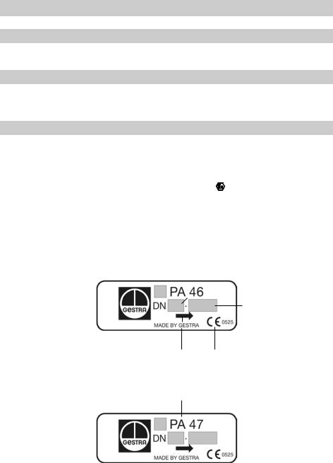
Name plate / Marking
According to EN 19 the name plate and the housing indicate the valve type and design:
■ Type designation |
PA 46, PA 47: |
Design with hand lever |
|
|
MPA 46, MPA 47: |
Design with diaphragm actuator |
|
■ Marking according to ATEX: |
Marking: |
II 2G/D c X |
|
■ Stamp on valve body, e. g. |
4 |
indicates term and year of production |
|||
04 |
|||||
(Example: 4th quarter 2004) |
|
|
|
|
|
|
|
Code letter “M” for |
Nominal size |
||
|
|
diaphragm actuator |
|
|
|
|
|
|
|
||
|
|
|
|
|
|
|
|
|
|
|
|
PN / CL
Direction of flow |
CE marking if required |
Type of equipment

Technical Data - continued -
Capacity chart PA 46, PA 47, MPA 46, MPA 47
Calculation of the amount of boiler water to be discharged according to the following formula:
A = |
Q · S |
|
|
|
|
K – S |
|
Example |
|
||
|
|
|
|||
Conductivity of |
|
Conductivity of |
|
||
feedwater: |
S [µS/cm] |
feedwater: |
S = 20 µS/cm |
||
Admissible conductivity |
|
Admissible conductivity |
|
||
of boiler water: |
K [µS/cm] |
of boiler water: |
K = 4000 µS/cm |
||
Boiler capacity: |
Q [kg/h] |
Boiler capacity: |
Q = 2000 kg/h |
||
Amount of boiler water |
|
Amount of boiler water |
A ≈ 10 kg/h |
||
to be discharged: |
A [kg/h] |
to be discharged: |
|||
|
|
|
|
How to read chart fig. 1 |
|
|
|
|
|
Boiler pressure: |
25 bar |
|
|
|
|
Nominal size of intermittent valve for removing boiler |
|
|
|
|
|
sludge |
DN 32 |
Fig. 1 |
|
Capacity: |
.5 kg/s |
||
10
 Loading...