


NRG 16-40

1
NRG 16-40
NRG 17-40
NRG 19-40
NRG 111-40
Installation Instructions 810590-03
Level Electrode NRG 16-40
Level Electrode NRG 17-40
Level Electrode NRG 19-40
Level Electrode NRG 111-40
GESTRA Steam Systems
GESTRA

2
Contents
Usage for the intended purpose ..............................................................................................................4
Safety note .............................................................................................................................................
4
Danger ...................................................................................................................................................4
Attention .................................................................................................................................................4
PED (Pressure Equipment Directive) ........................................................................................................
4
ATEX (Atmosphère Explosible) .................................................................................................................
4
Important Notes
Page
Explanatory Notes
Scope of supply ......................................................................................................................................
5
Description .............................................................................................................................................5
Function .................................................................................................................................................6
System components ...............................................................................................................................
6
Design .................................................................................................................................................... 6
NRG 16-40, NRG 17-40, NRG 19-40, NRG 111-40, step 1 ..................................................................... 15
NRG 16-40, NRG 17-40, NRG 19-40, NRG 111-40, step 2 ..................................................................... 15
Attention ...............................................................................................................................................15
Note .....................................................................................................................................................15
Tools ..................................................................................................................................................... 15
Examples of installation NRG 16-40, NRG 17-40, NRG 19-40 ...............................................................16
Examples of installation NRG 111-40 .................................................................................................. 17
Key .......................................................................................................................................................18
Installation
NRG 16-40, NRG 17-40, NRG 19-40, NRG 111-40 ..................................................................................
7
Corrosion resistance ...............................................................................................................................
8
Sizing .....................................................................................................................................................8
Name plate / marking .............................................................................................................................
8
Dimensions 16-40, NRG 17-40, NRG 19-40 ............................................................................................9
Dimensions NRG 111-40 ......................................................................................................................10
Technical Data
NRG 16-40, NRG 17-40, NRG 19-40 ..................................................................................................... 11
NRG 111-40 .........................................................................................................................................
12
Key .......................................................................................................................................................14
Design
NRG 16-40, NRG 17-40, NRG 19-40, NRG 111-40 ................................................................................13
Key .......................................................................................................................................................14
Functional Elements

3
Emergency operation of water-level limiting system..............................................................................25
Attention ...............................................................................................................................................25
Emergency Operation
Danger .................................................................................................................................................27
Disposal................................................................................................................................................27
Decommissioning
Wiring
NRG 16-40, NRG 17-40, NRG 19-40, NRG 111-40 ................................................................................19
Aligning terminal box ............................................................................................................................ 19
Note .....................................................................................................................................................19
Wiring diagram ..................................................................................................................................... 20
Attention ...............................................................................................................................................21
Tools ..................................................................................................................................................... 21
Contents continued
Page
Basic Settings
CAN Bus ...............................................................................................................................................
22
Node ID ................................................................................................................................................
22
Attention ...............................................................................................................................................22
Factory set default values .....................................................................................................................
22
Water-level limiting system ...................................................................................................................23
Factory set default node IDs ..................................................................................................................23
Assigning / changing node ID ................................................................................................................23
Attention ...............................................................................................................................................23
Setting code switch ..............................................................................................................................24
Commissioning
Wiring check .........................................................................................................................................25
Apply mains voltage
..............................................................................................................................25
Operation
Low-level limiter water-level limiting system ........................................................................................25
Note .....................................................................................................................................................25
Malfunctions
Fault finding list for troubleshooting ...................................................................................................... 26
Annex
Declaration of conformity ......................................................................................................................27
4
Important Notes
Danger
When loosening the electrode steam or hot water might escape.
This presents the danger of severe scalding. It is therefore essential not to remove
the electrode unless the boiler pressure is verified to be zero.
The electrode is hot during operation. This presents the danger of severe burns to hands
and arms. Installation and maintenance work should only be carried out when the
system is cold.
If the internal ceramic insulation breaks, hot steam can escape through the lateral vent
hole on the electrode body. This presents the risk of severe scalding. Do not stay near
the electrode during operation.
Usage for the intended purpose
Use level electrodes type NRG 16-40, NRG 17-40, NRG 19-40 and NRG 111-40 in conjunction with level
switch NRS 1-40 or NRS 1-40.1 only as low-water level limiters (low-level alarms).
Safety note
The equipment must only be installed and commissioned by qualified staff.
Maintenance and service work must only be performed by adequately trained persons who have
a recognized level of competence.
PED (Pressure Equipment Directive)
The equipment fulfills the requirements of the Pressure Equipment Directive (PED) 97/23/EC.
Applicable in fluids of group 1 and 2. With CE marking (apart from equipment according to section 3.3).
Attention
The name plate indicates the technical specification of the equipment.
Do not commission or operate equipment without a name plate.
ATEX (Atmosphère Explosible)
According to the European Directive 94/9/EC the equipment must
not be used in explosion-risk areas.

5
Explanatory Notes
Scope of supply
NRG 16-40
1 Level electrode type NRG 16-40
1 S. S. joint ring D 27 x 32 mm to DIN 7603 (made of 1.4301), bright annealed
1 Terminating resistor 120
Ω
1 Installation manual
NRG 17-40
1 Level electrode type NRG 17-40
1 S. S. joint ring D 27 x 32 mm to DIN 7603 (made of 1.4301), bright annealed
1 Terminating resistor 120
Ω
1 Installation manual
NRG 19-40
1 Level electrode type NRG 19-40
1 S. S. joint ring D 27 x 32 mm to DIN 7603 (made of 1.4301), bright annealed
1 Terminating resistor 120
Ω
1 Installation manual
NRG 111-40
1 Level electrode type NRG 111-40
1 S. S. joint ring D 33 x 39 mm to DIN 7603 (made of 1.4301), bright annealed
1 Terminating resistor 120
Ω
1 Installation manual
Description
The level electrode NRG 1...-40 works according to the conductivity measurement principle.
The NRG 1...-40 is designed for use in conductive liquids to detect the minimum liquid level:
■ One level with one switchpoint.
The NRG 1...-40 is used in combination with switching controller NRS 1-40 or NRS 1-40.1 or further
system components. NRG 1...-40 in conjunction with the associated control equipment constitutes a
water level limiter with periodic self-testing routine (SMART function) in accordance with TRD 604,
sheet 1 and 2 and EN regulations. The level data are transferred from the electrode NRG 1...-40 to the
control unit via a CAN bus using the CANopen protocol.

6
Explanatory continued
Function
The conductivity of the liquid is used to signal the liquid level. Some liquids are conductive, which
means that they allow an electric current to flow through them. For the safe functioning of this device
a minimum conductivity of the liquid to the monitored is required.
The conductivity measurement method can detect two conditions: electrode rod submerged or
exposed, meaning switchpoint reached (or exceeded) or not yet reached. Before installation, the length
of the electrode rod must be cut to the required switching levels, e. g. cut-out of the burner circuit or
interruption of the burner-protection circuit.
The system incorporates an additional electrode that provides automatic monitoring of the electrical
resistance path between the measuring electrode and the earth. When the measured value falls below
the admissible resistance value the burner shutdown is endorsed by interruption of the burner
protection circuit.
At regular intervals, the level electrode NRG 1...-40 sends a data telegram to the switching controller
NRS 1-40. The data transfer is effected by means of a CAN bus according to DIN ISO 11898 using the
CANopen protocol.
One switching controller type NRS 1-40 or NRS 1-40.1 can be used for two level electrodes
NRG 1...-40 (low-level limiting system
).
System components
NRS 1-40
Digital switching controller for low-level limiter NRG 1...-40
Functions: Low-level alarm (
min)
Data exchange: CAN bus to DIN ISO 11898 using CANopen protocol.
NRS 1-40.1
Digital control equipment for level electrodes NRG 1...-40 (low water), one level electrode
NRG 1...-41 (high level) and a safety temperature limiter TRG 5-6... / TRV 5-40.
Functions:
min alarm, max alarm, max temperature (freely configurable combinatons)
Data exchange: CAN bus to DIN ISO 11898 using CANopen protocol.
URB 1, URB 2
Control terminal and display unit
Functions: Parameterization and visual display (LCD)
Data exchange: CAN bus to DIN ISO 11898 using CANopen protocol
Design
NRG 16-40, NRG 17-40, NRG 19-40:
Screwed ¾", EN ISO 228-1. Fig. 2
NRG 111-40:
Screwed 1", EN ISO 228-1. Fig. 3

7
NRG 16-40, NRG 17-40, NRG 19-40, NRG 111-40
Type Approval Nº
TÜV · SWB / SHWS · 02-403
EG BAF-MUC 02 02 103881 002
Service pressure
NRG 16-40, PN 40 NRG 17-40, PN 63 NRG 19-40, PN 160 NRG 111-40, PN 320
32 bar g (464 psig) 60 bar g (870 psig) 100 barg (1450 psig) 183 bar g (2652 psig)
at 238°C at 275°C at 311 °C at 357°C
Connection
Screwed ¾" BSP, EN ISO 228-1 (NRG 16-40, NRG 17-40, NRG 19-40)
Screwed 1" BSP, EN ISO 228-1 (NRG 111-40)
Materials
Terminal box: Die cast aluminium 3.2161 (G AlSi8Cu3)
Stem: S. S. 1.4571 (X6CrNiMoTi17 12 2)
Measuring electrode: S. S. 1.4401 (X5CrNiMo17 12 2)
Electrode insulation: Gylon
®
(NRG 16-40, NRG 17-40, NRG 19-40)
Electrode insulation: PEEK (NRG 111-40)
Lengths supplied
500 mm, 1000 mm, 1500 mm, 2000 mm, 2500 mm, 3000 mm
Sensitivity of response
> 0.5
µS/cm at 25°C.
Supply voltage
18 – 36 V DC (coming from NRS 1-40 / NRS 1-40.1)
Current consumption
35 mA
Fuse
Electronic thermal fuse T
max
= 85 °C, hysteresis 2K
Hysteresis
-2 K
Electrode voltage
2 V
ss
Data exchange
CAN bus to DIN ISO 11898, CANopen protocol
Indicators and adjustors
One 10-pole code switch for node ID and baud rate settings
One wire link (for switching between electrode 1 and electrode 2)
Electric connection
M 12 sensor connector, 5 poles, A-coded,
M 12 sensor jack, 5 poles, A-coded
Protection
IP 65 to DIN EN 60529
Max. admissible ambient temperature
70 °C
Weight
approx. 2.5 kg
Technical Data
8
Corrosion resistance
When used for its intended purpose the safe functioning of the electrode will not be impaired by
corrosion.
Technical Data continued
Sizing
The electrode body must not be subjected to sharp increases in pressure. Welds and flanges of the
electrode are designed to withstand dynamic loading (bending and alternating stress). The dimensional
allowances for corrosion reflect the latest state of technology.
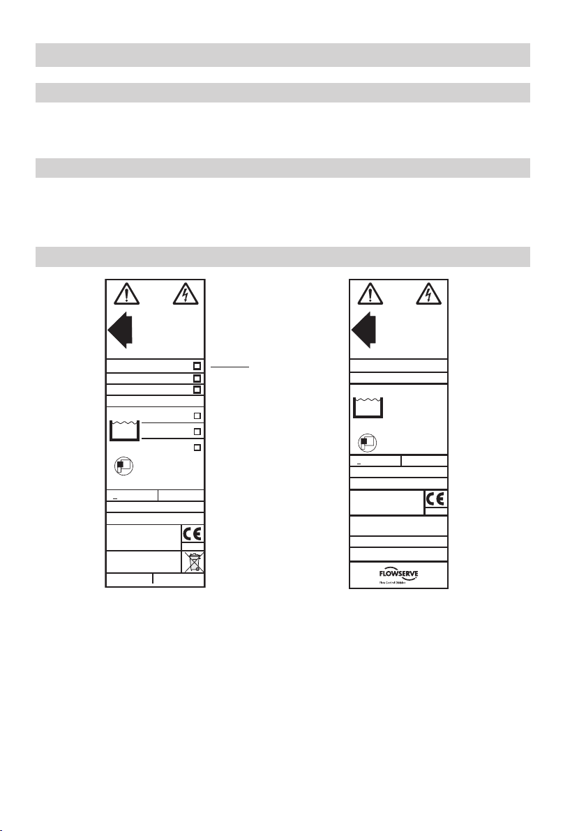
Name plate / marking
Fig. 1
Designation of
the equipment
TÜV . SWB / SHWS.
02 - 403
0525
GESTRA AG
Münchener Str. 77
D-28215 Bremen
18-36 V DC0,5 µS/cm>
Betriebsanleitung beachten
See installation instructions
Voir instructions de montage
Tmax = 70 °C (158 °F)
IN/OUT: CAN-Bus
PN 63
PN 160
PN 40
PmaPmax
TmaTmax
NRG 17 - 40
NRG 19 - 40
NRG 16 - 40
G 3 /4 1.4571 IP65
60 bar (876 psi)
275 °C (527 °F)
32 bar (464 psi)
238 °C (460 °F)
100 bar (1450 psi)
311 °C (592 °F)
Node ID: _ _ _ _ __
VS-Nr.: 08 Mat-Nr.: 392084
0525
GB Reg. Design 2 053 113
US Pat. 5 719 342, 5805 052,
Design 383 403
18-36 V DC0,5 µS/cm>
Tmax = 70 °C (133 °F )
IN/OUT: CAN-Bus
PmaxPmax
TmaxTmax
NRG 111 - 40
G 1 1.4529 IP65
180 bar (2611 psi)
357 °C (675 °F)
Node ID: __ __ __
Münchener Str. 77, D-28215 Bremen
SER Nr.:
GESTRA AG
TÜV .
SWB / SHWS . 02 - 403
Betriebsanleitung beachten
See installation instructions
Voir instructions de montage
9
PROD UCT
DESI GNA WARD
MIN
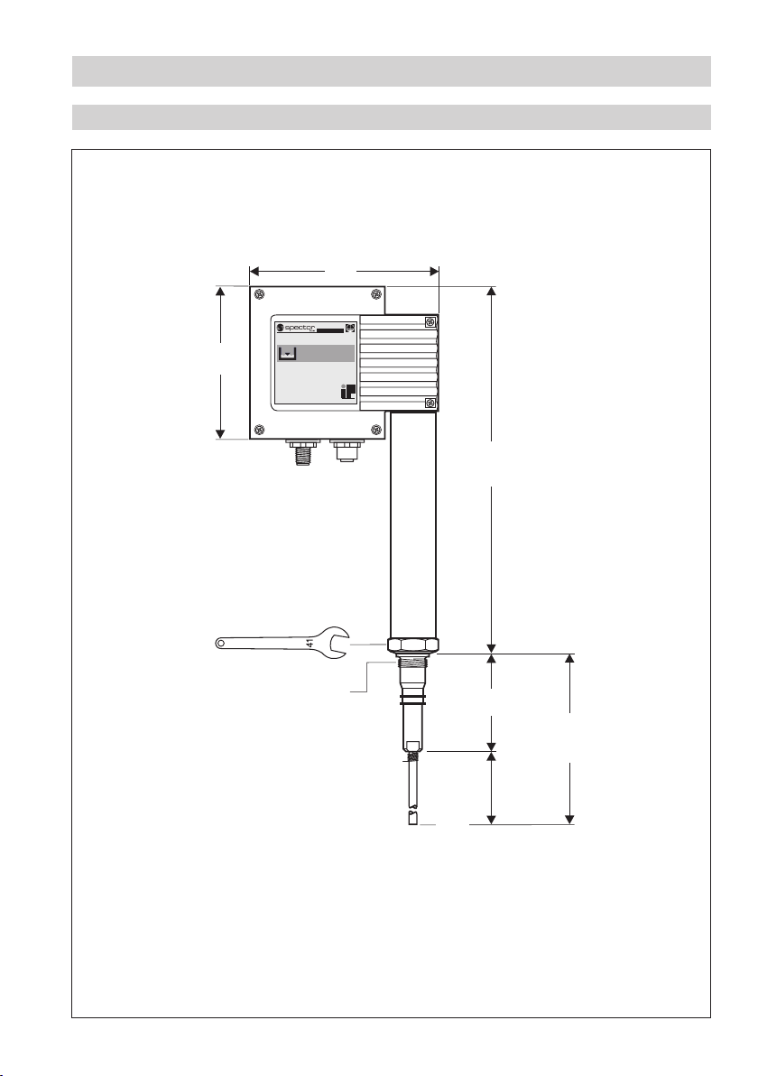
Fig. 2
¾" BSP, EN ISO 228-1
500, 1000, 1500,
2000, 2500, 3000
140
337.5
85
≥ 185
b = 70
Technical Data continued
Dimensions NRG 16-40, NRG 17-40, NRG 19-40
175
mm
A.F.
 Loading...