


Automax Logix 3200IQ Digital Positioner
Installation, Operation and Maintenance Instructions
Flowserve Corporation |
1350 N. Mountain Springs Parkway |
1978 Foreman Dr. |
Flow Control Division |
Springville, Utah 84663-3004 |
Cookville, TN 38501 |
www.flowserve.com |
Phone: 801 489 2233 |
Phone: 931 432 4021 |
|
|
|
Logix 3200IQ Digital Positioner
Terms Concerning Safety
The safety terms DANGER, WARNING, CAUTION and NOTE are used in these instructions to highlight particular dangers and/or to provide additional information on aspects that may not be readily apparent.
 DANGER: indicates that death, severe personal injury and/or substantial property damage will occur if proper precautions are not taken.
 WARNING: indicates that death, severe personal injury and/or substantial property damage can occur if proper precautions are not taken.
 CAUTION: indicates that minor personal injury and/or property damage can occur if proper precautions are not taken.
NOTE: indicates and provides additional technical information, which may not be very obvious even to qualified personnel. Compliance with other, not
particularly emphasized notes, with regard to transport, assembly, operation and maintenance and with regard to technical documentation (e.g., in the operating instruction, product documentation or on the product itself) is essential, in order to avoid faults, which in themselves might directly or indirectly cause severe personal injury or property damage.
General Information
The following instructions are designed to assist in unpacking, installing and performing maintenance as required on Automax Logix® 3200IQ digital positioners. Series 3000 is the term used for all the positioners herein; however, specific numbers indicate features specific to model (i.e., Logix 3200 indicates that the positioner has HART® protocol). See Logix 3200IQ Product Specification Sheet (AXAPS3200-00) for a breakdown of specific model numbers. Product users and maintenance personnel should thoroughly review this bulletin prior to installing, operating, or performing any maintenance on the valve.
To avoid possible injury to personnel or damage to valve parts, WARNING and CAUTION notes must be strictly followed. Modifying this product, substituting non-factory parts or using maintenance procedures other than outlined could drastically affect performance and be hazardous to personnel and equipment, and may void existing warranties.
 WARNING: Standard industry safety practices must be adhered to when working on this or any process control product. Specifically, personal protective and lifting devices must be used as warranted.
Table of Contents
Terms Concerning Safety . . . . . . . . . . . . . . . . . . . . . . . . . . 1 General Information. . . . . . . . . . . . . . . . . . . . . . . . . . . . . . 1
Logix 3200IQ Positioner Overview . . . . . . . . . . . . . . . . . . . 2
Specifications . . . . . . . . . . . . . . . . . . . . . . . . . . . . . . . . . . 2
Positioner Operation . . . . . . . . . . . . . . . . . . . . . . . . . . . . . 3
Detailed Sequence of Positioner Operations . . . . . . . . . . . . 4 Mounting the Positioner . . . . . . . . . . . . . . . . . . . . . . . . . . 5
Tubing Positioner to Actuator . . . . . . . . . . . . . . . . . . . 6
Wiring and Grounding Guidelines. . . . . . . . . . . . . . . . . . . . 6
4-20 mA Command Input Wiring . . . . . . . . . . . . . . . . 6 Grounding Screw . . . . . . . . . . . . . . . . . . . . . . . . . . . . 7 Compliance Voltage . . . . . . . . . . . . . . . . . . . . . . . . . . 7 Cable Requirements . . . . . . . . . . . . . . . . . . . . . . . . . . 8
Intrinsically Safe Barriers . . . . . . . . . . . . . . . . . . . . . . 8
Startup . . . . . . . . . . . . . . . . . . . . . . . . . . . . . . . . . . . . . . . 8 Logix 3200IQ Local Interface Operation. . . . . . . . . . . . 8 Initial DIP Switch Settings. . . . . . . . . . . . . . . . . . . . . . 8 Description of Configuration DIP Switch Settings . . . . 9
Description of Cal DIP Switch Settings . . . . . . . . . . . 10
QUICK-CAL Operation . . . . . . . . . . . . . . . . . . . . . . . . 11 Manual Jog Calibration Operation . . . . . . . . . . . . . . . 11 Local Control of Valve Position . . . . . . . . . . . . . . . . . 11 Factory Reset . . . . . . . . . . . . . . . . . . . . . . . . . . . . . . 11
Command Source Reset . . . . . . . . . . . . . . . . . . . . . . 11
Logix 3200IQ Status Condition . . . . . . . . . . . . . . . . . 11 Version Number Checking. . . . . . . . . . . . . . . . . . . . . 13 SoftTools™ Configuration and Diagnostic Software and HART 275/375 Handheld Communicator . . . . . . . . . . 13
Maintenance and Repair. . . . . . . . . . . . . . . . . . . . . . . . . . 14
Driver Module Assembly . . . . . . . . . . . . . . . . . . . . . . 14 Regulator . . . . . . . . . . . . . . . . . . . . . . . . . . . . . . . . . 16 Checking or Setting Internal Regulator Pressure . . . . 17
Spool Valve . . . . . . . . . . . . . . . . . . . . . . . . . . . . . . . 17
Spool Valve Cover. . . . . . . . . . . . . . . . . . . . . . . . . . . 18
Stem Position Sensor . . . . . . . . . . . . . . . . . . . . . . . . 18
Main PCB Assembly . . . . . . . . . . . . . . . . . . . . . . . . . 20 Customer Interface Board . . . . . . . . . . . . . . . . . . . . . 21
Optional Hardware . . . . . . . . . . . . . . . . . . . . . . . . . . . . . . 22
Vented Design . . . . . . . . . . . . . . . . . . . . . . . . . . . . . 22
HART VHF Filter . . . . . . . . . . . . . . . . . . . . . . . . . . . . 22
HART Modem . . . . . . . . . . . . . . . . . . . . . . . . . . . . . . 23 4-20 mA Analog Output Board . . . . . . . . . . . . . . . . . 23
Exploded View . . . . . . . . . . . . . . . . . . . . . . . . . . . . . . . . 25
Parts List . . . . . . . . . . . . . . . . . . . . . . . . . . . . . . . . . 26
Logix 3200IQ Spare Parts Kits . . . . . . . . . . . . . . . . . . . . . 27 Logix 3200IQ Mounting Kits . . . . . . . . . . . . . . . . . . . . . . 28 Logix O.E.M. Mounting Kits . . . . . . . . . . . . . . . . . . . 28 NAMUR Accessory Mounting Kit Part Numbers . . . . . 28
Frequently Asked Questions . . . . . . . . . . . . . . . . . . . . . . . 29 Troubleshooting. . . . . . . . . . . . . . . . . . . . . . . . . . . . . . . . 30
FCD AXAIM3200-00 |
9/04 |
Page: 1 of 32 |
© 2004, Flowserve Corporation, |
Printed in USA |
|

Automax Logix 3200IQ Digital Positioner
Installation, Operation and Maintenance Instructions
Flowserve Corporation |
1350 N. Mountain Springs Parkway |
1978 Foreman Dr. |
Flow Control Division |
Springville, Utah 84663-3004 |
Cookville, TN 38501 |
www.flowserve.com |
Phone: 801 489 2233 |
Phone: 931 432 4021 |
|
|
|
Figure 1: Logix 3200IQ Digital Positioner
Positioner Overview
The Logix 3200IQ digital positioner is a two-wire
4-20 mA input digital valve positioner. The positioner is configurable through the local user interface. The Logix 3200IQ utilizes the HART protocol to allow two-way remote communications with the positioner. The Logix 3200IQ positioner can control both doubleand singleacting actuators with linear or rotary mountings. The positioner is completely powered by the 4-20 mA input signal. Start up current must be at least 3.6 mA without AO card or 3.85 mA with AO card.
Specifications
Table I: Electrical Specifications
Power Supply |
Two-wire, 4-20 mA |
10.0 to 30.0 VDC |
|
Compliance Voltage |
10.0 VDC @ 20 mA |
|
495 Ω @ 20 mA Typical |
Effective Resistance |
Add 20 Ω when HART |
|
communication active |
Communications |
HART Protocol |
Minimum Operating |
3.6 mA without AO board |
Current |
3.85 mA with AO board |
Maximum Voltage |
30.0 VDC |
|
|
Table II: SoftTools Suite Software Specifications
Computer |
Minimum Pentium processor running |
|
|||
|
Windows 95, 98, NT, 2000, XP, 32 MB |
|
|||
|
total memory (64 MB recommended), |
|
|||
|
30 MB available hard disk space, |
|
|||
|
CD-ROM drive |
|
|
||
Ports |
1 minimum available with 8 maximum |
|
|||
|
possible. (Can also communicate via |
|
|||
|
|
PCMCIA and USB connections) |
|
||
HART Modem |
RS-232/PCMCIA card/USB |
|
|||
HART Filter |
May be required in conjunction with |
|
|||
|
some DCS hardware |
|
|
||
HART MUX |
MTL 4840/ELCON 2700 |
|
|
||
Table III: Environmental Conditions |
|
||||
|
|
|
|
|
|
|
|
Standard |
|
-4° to 176°F |
|
Operating Temperature |
|
(-20° to 80°C) |
|
||
|
|
|
|||
Range |
|
Low |
|
-40° to 176°F |
|
|
|
|
(-40° to 80°C) |
|
|
|
|
|
|
|
|
Transport and Storage |
-40° to 176°F (-40° to 80°C) |
|
|||
Temperature Range |
|
||||
|
|
|
|
||
Operating Humidity |
0 to 100% non-condensing |
|
|||
|
|
|
|
|
|
Note: The air supply must conform to ISA Standard ISA 7.0.01 (a dew point at least 18 degrees Fahrenheit below ambient temperature, particle size below five microns – one micron recommended – and oil content not to exceed one part per million).
Table IV: Physical Specifications
Housing Material |
Cast, powder-painted aluminum, |
||
|
stainless steel |
||
Soft Goods |
Buna-N / Fluorosilicone |
||
Weight |
8.3 pounds (3.9 kg) aluminum |
||
20.5 pounds (9.3 kg) stainless steel |
|||
|
|||
Table V: Positioner Specifications |
|||
|
|
|
|
Deadband |
|
<0.1% full scale |
|
Repeatability |
|
<0.05% full scale |
|
Linearity |
|
<0.5% (rotary), <0.8%, |
|
|
(sliding stem) full scale |
||
|
|
||
Air Consumption |
|
<0.3 SCFM (0.5 Nm3/hr) |
|
|
@ 60 psi (4 barg) |
||
|
|
||
FCD AXAIM3200-00 |
9/04 |
Page: 2 of 32 |
© 2004, Flowserve Corporation, |
Printed in USA |
|

Automax Logix 3200IQ Digital Positioner
Installation, Operation and Maintenance Instructions
Flowserve Corporation |
1350 N. Mountain Springs Parkway |
1978 Foreman Dr. |
Flow Control Division |
Springville, Utah 84663-3004 |
Cookville, TN 38501 |
www.flowserve.com |
Phone: 801 489 2233 |
Phone: 931 432 4021 |
|
|
|
Table VI: 4 to 20 mA Analog Output Specifications
Potential Range |
40° to 95° |
|
of Rotation |
||
|
||
Power Supply Range |
12.5 to 40 VDC, (24 VDC typical) |
|
Maximum Load |
(Supply voltage - 12.5) / 0.02 |
|
Resistance (ohms) |
||
|
||
Current Signal Output |
4-20 mA |
|
Linearity |
1.0% F.S. |
|
Repeatability |
0.25% F.S. |
|
Hysteresis |
1.0% F.S. |
|
Operating Temperature |
-40° to 176°F, -40° to 80°C |
|
|
|
Table VII: Hazardous Area Certifications
Explosion Proof
Class I, Div 1, Groups A, B, C, D
Class II, Div 1,
Groups E, F, G
(See Figure 2 for installation requirements.)
CENELEC
|
|
|
|
II 1G EEx ia IIC T4, T5 |
Intrinsically Safe |
|
T4 Ta = -40°C to 80°C |
||
|
|
|
|
T5 Ta = -40°C to 35°C |
Flameproof |
|
II 2 GD EEx d IIB + H2 |
||
|
|
|
|
T5, Ta = -40°C to 80°C |
|
|
Compliant |
|
|
|
|
|
||
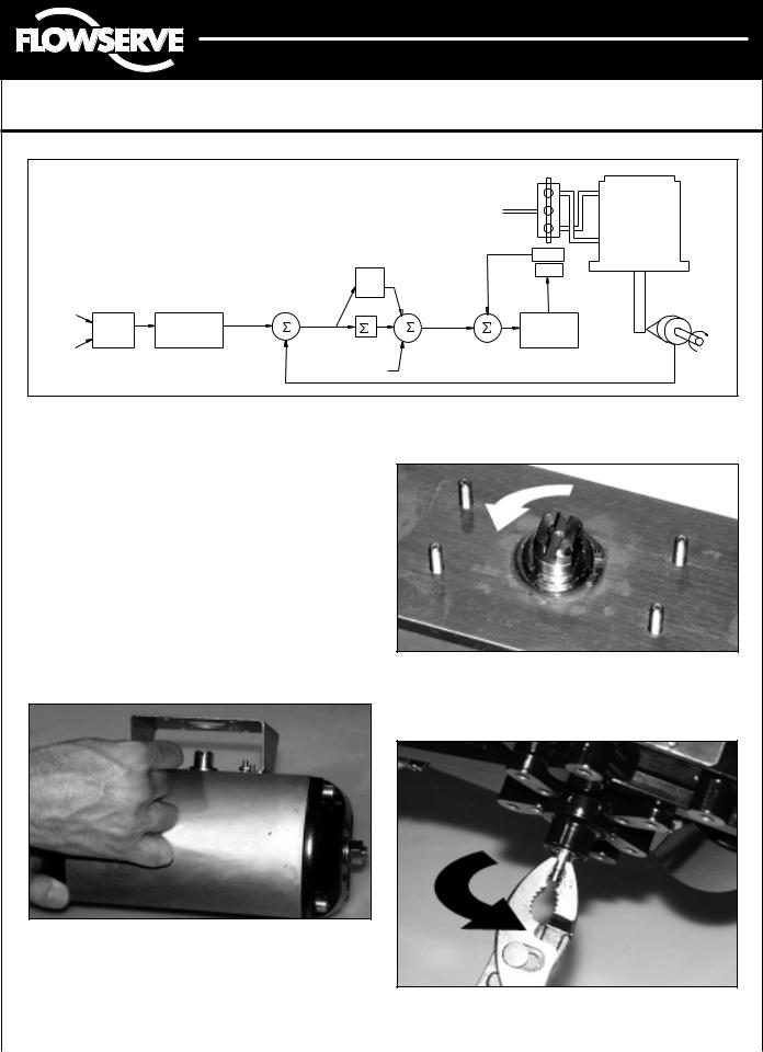
Positioner Operation
The Logix 3200IQ positioner is an electric feedback instrument. Figure 2 shows a Logix 3200IQ positioner installed on a double-acting actuator.
The Logix 3200IQ receives power from the two-wire, 4-20 mA input signal. However, since this positioner utilizes HART communications, two sources can be used for the command signal: Analog and Digital. In Analog source, the 4-20 mA signal is used for the command source. In Digital source, the level of the input 4-20 mA signal is ignored and a digital signal, sent via HART,
is used as the command source. The command source selection can be accessed with SoftTools software, the HART 275/375 communicator, or other host software.
The input signal in percent passes through a characterization/limits modifier block. The positioner no longer uses CAMs or other mechanical means to characterize the output of the positioner. This function is done in software, which allows for in-the-field customer adjustment. The positioner has three basic modes: Linear, Equal Percent (=%) and Custom characterization. In Linear mode, the input signal is passed straight through to the control algorithm in a
1:1 transfer. In Equal Percent (=%) mode, the input signal is mapped to a standard 30:1 rangeability =% curve.
If Custom characterization is enabled, the input signal is mapped to either a default =% output curve or a
custom, user-defined 21-point output curve. The custom
|
HART |
Analog Output Signal |
Main PCB |
Digital Position Algorithm |
|
|
Terminals |
|
|
|
|
|
Command |
|
|
|
|
|
Input Signal |
|
|
|
|
|
Spool Valve |
Pressure |
Air Supply |
|
|
Air-to-Open |
Exhaust |
Sensor Board |
|
|
|
Flame |
|
|
|
||
Configuration |
|
Arrestor |
|
|
|
|
Output 1 |
|
|
|
|
|
|
|
|
Flame |
|
|
|
|
|
Arrestor |
|
|
Output 2 |
|
|
|
|
|
|
|
|
|
LED |
|
|
|
|
Filter |
Display |
|
|
|
|
|
|
|
Flame |
|
|
|
|
|
Arrestor |
|
|
|
|
Steam |
Hall Effect |
|
|
|
|
Position |
|
|
|
Regulator |
|
Sensor |
Sensor |
|
|
|
|
|
Piezo Valve |
|
|
|
|
Figure 2: Logix 3200IQ Digital Positioner Schematic (air-to-open configuration)
FCD AXAIM3200-00 |
9/04 |
Page: 3 of 32 |
© 2004, Flowserve Corporation, |
Printed in USA |
|

Automax Logix 3200IQ Digital Positioner
Installation, Operation and Maintenance Instructions
Flowserve Corporation |
1350 N. Mountain Springs Parkway |
1978 Foreman Dr. |
Flow Control Division |
Springville, Utah 84663-3004 |
Cookville, TN 38501 |
www.flowserve.com |
Phone: 801 489 2233 |
Phone: 931 432 4021 |
|
|
|
user-defined 21-point output curve is defined using a handheld or PC software. In addition, two user-defined features, Soft Limits and MPC (Minimum Position Cutoff), may affect the final input signal. The actual command being used to position the stem, after any characterization or user limits have been evaluated, is called the Control Command.
The Logix 3200IQ uses a two-stage, stem-positioning algorithm. The two stages consist of an inner-loop, spool control and an outer-loop, stem position control. Referring again to Figure 1, a stem position sensor provides a measurement of the stem movement. The
Control Command is compared against the Stem Position.
If any deviation exists, the control algorithm sends a signal to the inner-loop control to move the spool up or down, depending upon the deviation. The inner-loop then quickly adjusts the spool position. The actuator pressures change and the stem begins to move. The stem movement reduces the deviation between Control Command and Stem Position. This process continues until the deviation goes to zero.
The inner-loop controls the position of the spool valve by means of a driver module. The driver module consists of a temperature-compensated hall effect sensor and a piezo valve pressure modulator. The piezo valve pressure
modulator controls the air pressure under a diaphragm by means of a piezo beam bender. The piezo beam deflects in response to an applied voltage from the inner-loop electronics. As the voltage to the piezo valve increases, the piezo beam bends, closing off against a nozzle causing the pressure under the diaphragm to increase. As the pressure under the diaphragm increases or decreases, the spool valve moves up or down respectively. The hall effect sensor transmits the position of the spool back to the inner-loop electronics for control purposes.
Detailed Sequence of Positioner Operations
A more detailed example explains the control function. Assume the unit is configured as follows:
•Unit is in Analog command source.
•Custom characterization is disabled (therefore characterization is Linear).
•No soft limits enabled. No MPC set.
•Valve has zero deviation with a present input signal of 12 mA.
•Loop calibration: 4 mA = 0% command, 20 mA = 100% command.
•Actuator is tubed and positioner is configured air-to-open.
Given these conditions, 12 mA represents a Command source of 50 percent. Custom characterization is disabled so the Command source is passed 1:1 to the Control Command. Since zero deviation exists, the Stem Position is also at 50 percent. With the stem at the desired position, the spool valve will be at a middle position that balances the pressures above and below the piston in the actuator. This is commonly called the null or balanced spool position.
Assume the input signal changes from 12 mA to 16 mA. The positioner sees this as a Command source of 75 percent. With Linear characterization, the Control Command becomes 75 percent. Deviation is the difference between Control Command and Stem Position: Deviation = 75% - 50% = +25%, where 50 percent is the present stem position. With this positive deviation, the control algorithm sends a signal to move the spool up from its present position. As the spool moves up, the supply air is applied to the bottom of the actuator and air is exhausted from the top of the actuator. This new pressure differential causes the stem to start moving towards the desired position of 75 percent. As the stem moves, the Deviation begins to decrease. The control algorithm begins to reduce the spool opening. This process continues until the Deviation goes to zero. At this point, the spool will be back in its null or balanced position. Stem movement will stop and the desired stem position is now achieved.
One important parameter has not been discussed to this point: Inner loop offset. Referring to Figure 3, a number called Inner loop offset is added to the output of the control algorithm. In order for the spool to remain in its null or balanced position, the control algorithm must output a non-zero spool command. This is the purpose of the Inner loop offset. The value of this number is equivalent to the signal that must be sent to the spool position control to bring it to a null position with zero deviation. This parameter is important for proper control and is optimized and set automatically during stroke calibration.
FCD AXAIM3200-00 |
9/04 |
Page: 4 of 32 |
© 2004, Flowserve Corporation, |
Printed in USA |
|
Automax Logix 3200IQ Digital Positioner
Installation, Operation and Maintenance Instructions
Flowserve Corporation |
1350 N. Mountain Springs Parkway |
1978 Foreman Dr. |
Flow Control Division |
Springville, Utah 84663-3004 |
Cookville, TN 38501 |
www.flowserve.com |
Phone: 801 489 2233 |
Phone: 931 432 4021 |
|
|
|
|
|
|
|
|
|
|
Air |
|
|
|
|
|
|
|
|
|
Supply |
|
|
|
|
|
|
|
|
|
|
Tubed |
|
|
|
|
|
|
|
|
|
ATO |
|
|
|
|
|
Control |
|
|
|
Sensor |
|
|
|
|
|
Algorithm |
|
|
|
||
|
|
|
|
|
|
|
|
||
|
|
|
|
Pmax |
|
Inner-Loop |
|
||
|
|
|
|
|
Output |
|
|
||
|
|
|
|
Pmin |
|
|
|
Piezo |
|
|
|
|
|
Gmult |
|
|
|
||
|
Input |
|
|
|
|
|
|
Valve |
|
4-20 mA |
|
|
|
|
|
|
Voltage |
||
Signal |
|
|
|
|
|
|
|||
(Analog |
|
Linear Mode |
CONTROL |
|
|
D/A |
– |
Inner |
|
Mode) |
|
Deviation |
+ |
Output |
|||||
Analog |
Characterization |
||||||||
|
+ |
I |
+ |
Percentage |
+ |
Loop |
|||
Command In |
Digital |
Soft Limits |
COMMAND |
– |
+ |
|
Spool |
||
|
|
|
|
Control |
|||||
(Digital |
|
MPC |
|
Integration |
|
|
|
||
|
|
|
Summer |
|
|
|
Stem |
||
Mode) |
|
|
|
|
|
|
|||
|
|
|
Inner |
|
|
|
|||
|
|
|
|
|
|
|
Position |
||
|
|
|
|
Loop |
|
|
|
Sensor |
|
|
|
|
|
Offset |
|
|
|
|
|
Figure 3: System Positioning Algorithm
Mounting the Positioner
 CAUTION: Positioner shaft is spring-loaded and features mechanical stops at each end of stroke. Failure to follow these procedures carefully may result in severe damage to positioner. Read through entire procedure before starting.
1.Attach positioner mounting bracket to actuator using fasteners supplied with bracket (Figure 4). Tighten bolts finger-tight only at this time.
2.Install coupler (if required – coupler is not required for NAMUR mounting) on actuator shaft, making sure it is centered.
Figure 5: Actuator Shaft
4.Carefully grasp positioner shaft with pliers as shown in Figure 6. Turn shaft to determine direction of rotation.
Figure 4: Linear Mark One Control Valve Mounting
3.Stroke the actuator to determine direction of rotation as shown in Figure 5. Pay specific attention to the slot
that will engage positioner shaft. |
Figure 6: Turn Positioner Shaft |
|
|
|
|
FCD AXAIM3200-00 |
9/04 |
Page: 5 of 32 |
© 2004, Flowserve Corporation, Printed in USA |
|
|
Automax Logix 3200IQ Digital Positioner
Installation, Operation and Maintenance Instructions
Flowserve Corporation |
1350 N. Mountain Springs Parkway |
1978 Foreman Dr. |
Flow Control Division |
Springville, Utah 84663-3004 |
Cookville, TN 38501 |
www.flowserve.com |
Phone: 801 489 2233 |
Phone: 931 432 4021 |
|
|
|
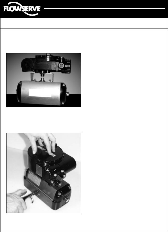
5.Making sure positioner shaft rotation matches actuator shaft rotation, place positioner on mounting bracket (Figure 7). Make sure shafts engage. Do not insert fasteners into positioner at this time.
Figure 7: Positioner on Mounting Bracket
6.Double-check actuator and positioner rotation. Hold positioner against bracket with fingertips as shown in Figure 8.
Figure 8: Check Positioner Shaft Alignment
 WARNING: Keep away from positioner sides, as positioner will suddenly rotate on bracket if not properly aligned and cause injury.
Slowly rotate the actuator. If the positioner shaft is properly aligned, the shaft will rotate freely. If not, the mechanical stops will grab, causing the positioner body to rotate on bracket.
7.If the shaft is not properly aligned, repeat steps 3-6. Otherwise, attach positioner to bracket with fasteners included with bracket. Tighten bolts finger-tight only at this time.
8.Stroke actuator/positioner several times to align shafts. Tighten all fasteners.
Tubing Positioner to Actuator
Proper tubing orientation is critical for the positioner to function correctly and have the proper failure mode. Referring to Figure 2, note that for air-to-open valves, the Output 1 port of the positioner manifold is tubed to the ‘open’ side of the actuator. The Output 2 port of the positioner manifold is tubed to the ‘closed’ side of the actuator. For air-to-close valves the above configuration is reversed.
Wiring and Grounding Guidelines
(See Figure 9)
 WARNING: This product has electrical conduit connections in either thread sizes 1/2" NPT or M20 which appear identical but are not interchangeable. Housings with M20 threads are stamped with the letters M20 above the conduit opening. Forcing dissimilar threads together will damage equipment, cause personal injury and void hazardous location certifications. Conduit fittings must match equipment housing threads before installation.
If threads do not match, obtain suitable adapters or contact a Flowserve representative.
4-20 mA Command Input Wiring
Verify polarity when making field termination connection. The Logix 3200 is reverse polarity protected. Wire 4-20 mA current source to the input terminal labeled 4-20 mA Input on the user interface board (see Figure 9). Never connect a voltage source directly across the Logix 3200IQ terminals. The current must always be limited for 4-20 mA operation. Minimum operating current is 3.6 mA.
The input loop current signal to the Logix 3200IQ digital positioner should be in shielded cable. Shields must be tied to a ground at only one end of the cable to provide a place for environmental electrical noise to be removed from the cable. In general, shield wire should be connected at the source.
FCD AXAIM3200-00 |
9/04 |
Page: 6 of 32 |
© 2004, Flowserve Corporation, |
Printed in USA |
|

Automax Logix 3200IQ Digital Positioner
Installation, Operation and Maintenance Instructions
Flowserve Corporation |
1350 N. Mountain Springs Parkway |
1978 Foreman Dr. |
Flow Control Division |
Springville, Utah 84663-3004 |
Cookville, TN 38501 |
www.flowserve.com |
Phone: 801 489 2233 |
Phone: 931 432 4021 |
|
|
|
NOTE: The Logix 3200IQ positioner carries an intrinsically safe barrier rating of 100 mA. Input currents should not exceed 100 mA.
HART |
ANALOG |
HART Terminals |
|
4-20 mA |
INPUT |
OUTPUT |
|
|
|
|
4-20 mA Feedback |
|
|
|
Terminals (Optional) |
|
|
|
Housing EARTH |
|
|
|
Terminal |
Field |
|
|
|
Terminators |
|
|
Connect Shield at Source |
|
|
|
|
|
|
|
Ground 4-20 mA Current Source |
|
|
|
Shielded Cable |
|
|
|
4-20 mA Current Source |
Figure 9: Field Termination
Grounding Screw
The green grounding screw, located inside the termination cap, should be used to provide the unit with an adequate and reliable earth ground reference. This ground should be tied to the same ground as the electrical conduit. Additionally, the electrical conduit should be earth grounded at both ends of its run.
 WARNING: The green grounding screw must not be used to terminate signal shield wires.
Compliance Voltage (See Figure 10)
Output compliance voltage refers to the voltage limit that can be provided by the current source. A current loop system consists of the current source, wiring resistance, barrier resistance (if present), and the Logix 3200IQ positioner impedance. The Logix 3200IQ digital positioner requires that the current loop system allows for a 10.0 VDC drop across the positioner at maximum loop current. The 10.0 VDC drop across the Logix 3200IQ positioner terminals is generated by the positioner from the 4-20 mA loop current input. The actual voltage at the terminals varies from 9.8 to 10.0 VDC depending on the current mA signal, HART communications and ambient temperature.
 WARNING: Never connect a voltage source directly across the positioner terminals. This could cause permanent circuit board damage.
Determine if the loop will support the Logix 3200IQ digital positioner by performing the following calculation.
Equation 1
Voltage = Compliance Voltage (@Currentmax) –
Currentmax • (Rbarrier+Rwire)
The calculated voltage must be greater than 10 VDC in order to safely support the Logix 3200IQ digital positioner.
Example:
DCS Compliance Voltage = 19 VDC
Rbarrier = 300 Ω
Rwire = 25 Ω
Currentmax = 20 mA
Voltage = 19 VDC – 0.020 A • (300 Ω + 25 Ω ) = 12.5 VDC
The voltage 12.5 VDC is greater than the required
10.0 VDC; therefore, this system will support the Logix 3200IQ digital positioner. The Logix 3200IQ positioner has a worst case input resistance equivalent to 500 Ω at a 20 mA input current.
|
|
If Present |
|
|
|
|
|
|
R |
R |
|
|
|
Current |
Compliance |
Barrier |
Wire |
10 VDC |
+ |
Logix |
|
|
|
||||
Source |
Voltage |
Current |
|
|
3200IQ |
|
|
|
– |
||||
|
|
|
|
|
Figure 10: Compliance Voltage
FCD AXAIM3200-00 |
9/04 |
Page: 7 of 32 |
© 2004, Flowserve Corporation, |
Printed in USA |
|
Automax Logix 3200IQ Digital Positioner
Installation, Operation and Maintenance Instructions
Flowserve Corporation |
1350 N. Mountain Springs Parkway |
1978 Foreman Dr. |
Flow Control Division |
Springville, Utah 84663-3004 |
Cookville, TN 38501 |
www.flowserve.com |
Phone: 801 489 2233 |
Phone: 931 432 4021 |
|
|
|
Cable Requirements
The Logix 3200IQ digital positioner utilizes the HART Communication protocol. This communication signal is superimposed on the 4-20 mA current signal. The two frequencies used by the HART protocol are 1200 Hz and 2200 Hz. In order to prevent distortion of the HART communication signal, cable capacitance and cable length restrictions must be calculated. The cable length must be limited if the capacitance is too high. Selecting a cable with lower capacitance/foot rating will allow longer cable runs. In addition to the cable capacitance, the network resistance also affects the allowable cable length.
In order to calculate the maximum network capacitance, use the following formula:
Equation 2
|
|
|
Cnetwork ( F) ≤ |
|
|
|
|
|
|
|
65 |
|
|
|
|
|
- 0.0032 |
|
|
|
|
|
|
|
|
|
|
|
|
|
|
|
|
|
|
|
|
||||
|
|
|
|
|
(Rbarrier + Rwire |
+ 390) |
|
|
|
|||||||||||
|
|
|
|
|
|
|
|
|
|
|
|
|
|
|
|
|
|
|
|
|
|
|
|
|
|
|
|
|
|
|
|
|
|
|
|||||||
|
Example: |
Rbarrier |
= |
300 Ω |
|
|
||||||||||||||
|
|
|
|
Rwire |
= |
50 Ω |
|
|
|
|
|
|
|
|
|
|||||
|
|
|
|
Ccable |
= |
22 pF = 0.000022 µ F |
|
|
||||||||||||
|
|
|
|
|
|
|
|
|
|
|
foot |
|
|
|
|
|
foot |
|
|
|
|
|
|
|
|
|
|
|
|
- 0.0032 = 0.08 µ F = Cmax network (µ f) |
|
||||||||||
|
|
65 |
|
|
|
|
|
|
|
|
||||||||||
|
|
(300 + 50 + 390) |
|
|
|
|
||||||||||||||
|
|
|
|
|
|
Cmax network (µ F) |
|
|
||||||||||||
|
Maximum Cable Length = |
|
|
|
||||||||||||||||
|
|
|
Ccable |
|
|
|
||||||||||||||
|
|
|
|
|
|
|
|
|
|
|
|
|
|
|
|
|||||
|
Maximum Cable Length = |
|
|
0.08 µ F |
= 3636 ft |
|
||||||||||||||
|
|
0.000022 µ F/foot |
|
|||||||||||||||||
|
|
|
|
|
|
|
|
|
|
|
|
|
|
|
|
|
|
|
|
|
To control cable resistance, 24 AWG cable should be used for runs less than 5000 feet. For cable runs longer than 5000 feet, 20 AWG cable should be used.
Intrinsically Safe Barriers
When selecting an intrinsically safe barrier, make sure the barrier is HART compatible. Although the barrier will pass the loop current and allow normal positioner control, if not compatible, it may prevent HART communication.
Startup
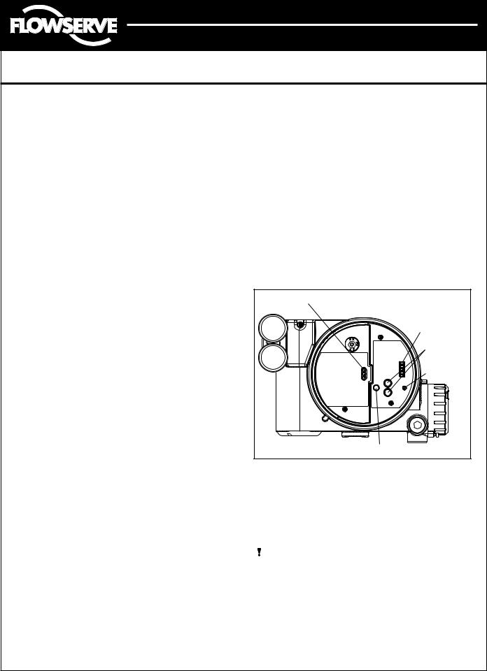
Logix 3200IQ Local Interface Operation
The Logix 3200IQ local user interface (Figure 11) allows the user to configure the basic operation of the positioner, tune the response and calibrate the positioner without additional tools or configurators. The Local interface consists of a QUICK-CAL button for automatic zero and span setting, along with two jog buttons (↑ and ↓ ) for spanning valve/actuators with no fixed internal stop in the open position. There is also a DIP switch block containing eight switches. Seven of the switches are for basic configuration settings and one is for calibration options.
There is also a rotary selector switch for adjusting the positioner gain settings. For indication of the operational status or alarm conditions there are also three LEDs on the local user interface.
LEDs |
DIP Switch Block |
Jog Buttons |
Rotary |
Selector |
Switch |
QUICK-CAL Button |
Figure 11: Local User Interface
Initial DIP Switch Settings
Before placing the unit in service, set the DIP switches in the Configuration and Cal boxes to the desired control options. A detailed description of each DIP switch setting follows.
NOTE: The Logix 3200IQ positioner reads the DIP switch settings each time the QUICK-CAL button is pressed. If a HART handheld or Flowserve PC software is used to configure and then calibrate the positioner, the DIP switches are not read. The auto-tune adjustment switch labeled “GAIN” is always live and can be adjusted at any time.
FCD AXAIM3200-00 |
9/04 |
Page: 8 of 32 |
© 2004, Flowserve Corporation, |
Printed in USA |
|

Automax Logix 3200IQ Digital Positioner
Installation, Operation and Maintenance Instructions
Flowserve Corporation |
1350 N. Mountain Springs Parkway |
1978 Foreman Dr. |
Flow Control Division |
Springville, Utah 84663-3004 |
Cookville, TN 38501 |
www.flowserve.com |
Phone: 801 489 2233 |
Phone: 931 432 4021 |
|
|
|
Description of Configuration DIP Switch Settings
The first seven DIP switches are for basic configuration. The function of each switch is described below.
Air Action
This must be set to match the configuration of the valve/actuator mechanical tubing connection and spring location since these determine the air action of the system.
ATO (air-to-open) – Selecting ATO if increasing output pressure from the positioner is tubed so it will cause the valve to open.
ATC (air-to-close) – Selecting ATC if increasing output pressure from the positioner is tubed so it will cause the valve to close.
Signal at Closed
Normally this will be set to 4 mA for an Air-to-open actuator and 20 mA for an Air-to-close actuator configuration.
4 mA – Selecting 4 mA will make the valve fully closed when the signal is 4 mA and fully open when the signal is 20 mA.
20 mA – Selecting 20 mA will make the valve fully closed when the signal is 20 mA and fully open when the signal is 4 mA.
=% Custom Linear
|
100 |
|
|
|
|
|
|
|
|
|
|
|
90 |
|
|
|
|
|
|
|
|
|
|
|
80 |
|
|
|
|
|
|
|
|
|
|
Command |
70 |
|
|
|
|
|
|
|
|
|
|
60 |
|
|
|
|
|
|
|
|
|
|
|
|
|
|
|
|
|
|
|
|
|
|
|
Control% |
50 |
|
|
|
|
|
|
|
|
|
|
40 |
|
|
|
|
|
|
|
|
|
|
|
|
|
|
|
|
|
|
|
|
|
|
|
|
30 |
|
|
|
|
|
|
|
|
|
|
|
20 |
|
|
|
|
|
|
|
|
|
|
|
10 |
|
|
|
|
|
|
|
|
|
|
|
0 |
|
|
|
|
|
|
|
|
|
|
|
0 |
10 |
20 |
30 |
40 |
50 |
60 |
70 |
80 |
90 |
100 |
% Command
Figure 12: Default Custom Characterization
Pos. Characterization
Linear – Select Linear if the actuator position should be directly proportional to the input signal.
Optional – Select Optional if another characteristic is desired, which is set in conjunction with the next switch, labeled Optional Pos. Char.
Optional Pos. Characterization
If the Pos. Characterization switch is set to optional then this switch is active with the following options:
=% – The =% option will characterize the actuator response to the input signal based on a standard 30:1 equal percent rangeability curve.
Custom – If Custom is selected, the positioner will be characterized to a custom table that must be set-up using a properly configured HART 275/375 handheld or other host software. Custom characterization can be thought of as a “soft CAM.” The user can define a characterization curve using 21 points. The control will linearly interpolate between points. Points do not have to be equally spaced in order to allow more definition at critical curve areas. The default values will linearize the output of a valve with an inherent =% characteristic (e.g., ball valves).
Table VIII: Characteristic Curve Data
% Command |
% Control Command |
|
||
=% |
Linear |
|
Custom |
|
|
|
|||
0 |
0 |
0 |
|
0 |
5 |
0.62 |
5 |
|
8.66 |
10 |
1.35 |
10 |
|
16.24 |
15 |
2.22 |
15 |
|
23.17 |
20 |
3.25 |
20 |
|
30.11 |
25 |
4.47 |
25 |
|
35.31 |
30 |
5.91 |
30 |
|
40.51 |
35 |
7.63 |
35 |
|
45.42 |
40 |
9.66 |
40 |
|
50.34 |
45 |
12.07 |
45 |
|
54.40 |
50 |
14.92 |
50 |
|
58.47 |
55 |
18.31 |
55 |
|
62.39 |
60 |
22.32 |
60 |
|
66.31 |
65 |
27.08 |
65 |
|
70.27 |
70 |
32.71 |
70 |
|
74.23 |
75 |
39.40 |
75 |
|
78.17 |
80 |
47.32 |
80 |
|
82.11 |
85 |
56.71 |
85 |
|
85.50 |
90 |
67.84 |
90 |
|
88.89 |
95 |
81.03 |
95 |
|
94.45 |
100 |
100.00 |
100 |
|
100.00 |
FCD AXAIM3200-00 |
9/04 |
Page: 9 of 32 |
© 2004, Flowserve Corporation, |
Printed in USA |
|
Automax Logix 3200IQ Digital Positioner
Installation, Operation and Maintenance Instructions
Flowserve Corporation |
1350 N. Mountain Springs Parkway |
1978 Foreman Dr. |
Flow Control Division |
Springville, Utah 84663-3004 |
Cookville, TN 38501 |
www.flowserve.com |
Phone: 801 489 2233 |
Phone: 931 432 4021 |
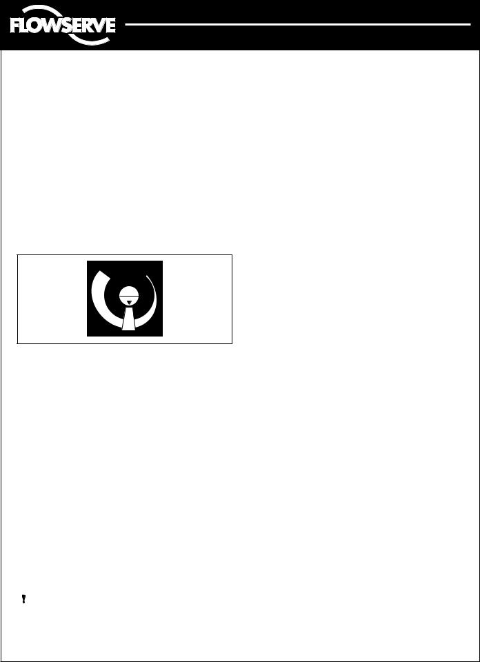
Auto Tune |
Configuration Switches |
|
This switch controls whether the positioner will auto tune itself every time the QUICK-CAL button is pressed or use preset tuning parameters.
On – On enables an auto tune feature that will automatically determine the positioner gain settings based on the current position of the adjustable GAIN switch setting and response parameters measured during the last QUICK-CAL. The GAIN switch is live, meaning the settings can be adjusted at any time by changing the rotary switch position. (Note that there is a small black arrow indicating the selection. The slot in the switch is NOT the indicator.)
GAIN
A
H B
G C
F D
E
Figure 13: Adjustable GAIN Switch
If the adjustable GAIN selector switch is set to “E” with the auto tune switch on, a Flowserve standard response tuning set will be calculated and used based on response parameters measured during the last QUICK-CAL.
If the adjustable GAIN selector switch is set to “D”, “C”, “B”, or “A” with the auto tune switch on, progressively lower gain settings will be used based on response parameters measured during the last QUICK-CAL.
If the adjustable GAIN selector switch is set to “F”, “G”, or “H” with the auto tune switch on, progressively higher gain settings will be calculated and used based on response parameters measured during the last QUICK-CAL.
Off – Off forces the positioner to use one of the factory preset tuning sets determined by the adjustable GAIN selector switch. Settings “A” through “H” are progressively higher gain predefined tuning sets. The GAIN selector switch is live and can be adjusted at any time to modify the tuning parameters.
NOTE: “E” is the default adjustable GAIN selector switch setting for all actuator sizes. Raising or lowering the gain setting is a function of the positioner/valve response to the control signal, and is not actuator size dependent.
Enabled – By selecting Enabled, the Logix 3200IQ will read all of the configuration switches each time a
QUICK-CAL is performed to determine the configuration.
Disabled – Selecting Disabled retains the last configuration in memory (from the last successful calibration) before the switch was set to Disabled. With this setting a QUICK-CAL only zeros and spans the positioner.
Stability Switch
This switch adjusts the position control algorithm of the positioner for use with low-friction control valves or high-friction automated valves.
Low-Friction Valves – Placing the switch to the left optimizes the response for low-friction, highperformance control valves. This setting provides for optimum response times when used with most low-friction control valves.
High-Friction Valves – Placing the switch to the right optimizes the response for valves and actuators with high friction levels. This setting slightly slows the response and will normally stop limit cycling that can occur on high-friction valves.
Description of Cal DIP Switch Settings
The eighth DIP switch selects between two calibration options. The function of the Cal DIP switch is described below.
Auto – Select Auto if the valve/actuator assembly has an internal stop in the open position. In Auto mode the positioner will fully close the valve and register the 0% position and then open the valve to the stop to register the 100% position when performing a self-calibration.
See detailed instructions in the next section on how to perform an auto positioner calibration.
Jog – Select Jog if the valve/actuator assembly has no physical calibration stop in the open position. In the Jog mode the positioner will fully close the valve for the 0% position and then wait for the user to set the open position using the Jog buttons labeled with the up and down arrows. See the detailed instructions in the next section on how to perform a manual calibration using the Jog buttons.
 WARNING: During the QUICK-CAL operation the valve may stroke unexpectedly. Notify proper personnel that the valve will stroke and make sure the valve is properly isolated.
FCD AXAIM3200-00 |
9/04 |
Page: 10 of 32 |
© 2004, Flowserve Corporation, |
Printed in USA |
|
 Loading...