


|
USER INSTRUCTIONS |
Limitorque ® SMB Series/SB Series |
Installation |
FCD LMENIM1401-04-AQ – 1/15 |
Operation |
|
Maintenance |
|
|
Experience In Motion

SMB Series/SB Series Installation and Maintenance FCD LMENIM1401-04-AQ – 01/15
Contents
1 |
Introduction |
6 |
||
|
|
|
||
|
2 Product Capabilities and Features |
7 |
||
|
|
|
||
|
3 |
Actuator Weights |
10 |
|
|
|
|
||
|
4 |
Installation Instructions |
11 |
|
|
|
|
|
|
|
|
4.1 |
Safety Precautions |
11 |
|
|
|
|
|
|
|
4.2 |
Safety Practices |
12 |
|
|
|
|
|
|
|
4.3 |
Actuator Preparation |
12 |
|
|
|
|
|
|
|
|
4.3.1 Mounting Base |
13 |
|
|
|
|
|
|
|
|
4.3.2 Stem Acceptance |
13 |
|
|
|
|
|
|
|
|
4.3.3 Terminal Connections |
14 |
|
|
|
|
|
|
|
4.4 |
Setting The Limit Switch |
14 |
|
|
|
|
|
|
|
|
4.4.1 Two-Train Geared Limit Switch |
15 |
|
|
|
|
|
|
|
|
4.4.2 Four-Train Geared Limit Switch |
18 |
|
|
|
|
|
|
|
4.5 |
Setting Torque Switch |
20 |
|
|
|
|
|
|
|
|
4.5.1 SMB-000 “Cam Style” Double Torque Switch |
20 |
|
|
|
|
|
|
|
|
4.5.2 SMB-000 and SMB-00 “C Style” Double Torque Switch |
23 |
|
|
|
|
|
|
|
|
4.5.3 SMB-0 through SMB-5 Double Torque Switch |
25 |
|
|
|
|
|
|
|
4.6 |
Position Indication |
27 |
|
|
|
|
|
|
|
|
4.6.1 Local Position Indicator |
27 |
|
|
|
|
|
|
|
|
4.6.2 Remote Position Indicator (50 ohm or 1000 ohm Potentiometer) |
27 |
|
|
|
|
|
|
|
|
4.6.3 Remote Position Indicator (Resistance-to-Current Signal Converter) |
28 |
|
|
|
|
|
|
|
4.7 |
Additional Electrical Components |
30 |
|
|
|
|
|
|
|
|
4.7.1 Reversing Starter |
30 |
|
|
|
|
|
|
|
|
4.7.2 Overload Relays |
30 |
|
|
|
|
|
|
|
|
4.7.3 Control Station |
31 |
|
|
|
||
|
5 |
Operation |
32 |
|
|
|
|
|
|
|
|
5.1 |
Motor Operation |
32 |
|
|
|
|
|
|
|
5.2 |
Manual Operation |
33 |
|
|
|
|
|
|
|
|
5.2.1 SMB-000 and SMB-00 |
33 |
|
|
|
|
|
|
|
|
5.2.2 SMB-0 through SMB-4 |
34 |
|
|
|
|
|
|
|
|
5.2.3 SMB-5 through SMB-5T |
34 |
|
|
|
||
|
6 |
Maintenance |
35 |
|
|
|
|
|
|
|
|
6.1 |
Routine Maintenance |
35 |
|
|
|
|
|
|
|
6.2 |
Major Maintenance |
36 |
|
|
|
|
|
|
|
6.3 |
Lubrication |
36 |
|
|
|
|
|
|
|
|
6.3.1 Lubrication Inspection |
36 |
|
|
|
|
|
|
|
|
6.3.2 Standard Lubricant |
37 |
|
|
|
|
|
|
|
|
6.3.3 Minimum Lubricant Qualities Required |
38 |
|
|
|
||
|
7 SMB Disassembly and Reassembly |
39 |
||
|
|
|
|
|
|
|
7.1 SMB-000 |
39 |
|
2 |
|
|
|
|
|
|
7.1.1 To Replace the Stem Nut Only |
39 |
|

SMB Series/SB Series Installation and Maintenance FCD LMENIM1401-04-AQ – 01/15
7.1.2 SMB-000 Disassembly |
40 |
7.1.3 SMB-000 Reassembly |
41 |
|
|
7.1.4 Gasket Instructions |
41 |
|
|
7.2 SMB-00 |
46 |
7.2.1 To Replace the Stem Nut Only |
46 |
|
|
7.2.2 SMB-00 Disassembly |
47 |
|
|
7.2.3 SMB-00 Reassembly |
48 |
7.2.4 Gasket Instructions |
49 |
|
|
7.3 SMB-0, 1, 2, 3 and 4 |
57 |
|
|
7.3.1 To Replace the Stem Nut Only |
57 |
7.3.2 SMB-0, 1, 2, 3 and 4 Disassembly |
58 |
|
|
7.3.3 Worm and Torque Spring Disassembly |
59 |
|
|
7.3.4 SMB-0, 1, 2, 3 and 4 Reassembly |
60 |
7.3.5 Gasket Instructions |
60 |
|
|
7.4 SMB-5 (Thrust and Torque) and SMB-5T (Torque Only) |
67 |
|
|
7.4.1 SMB-5 and SMB-5T Disassembly |
67 |
7.4.2 SMB-5 and SMB-5T Reassembly |
70 |
|
|
8 SB Disassembly and Reassembly |
80 |
|
|
8.1 SB-00 |
80 |
8.1.1 SB-00 Disassembly/Stem Nut Removal |
80 |
|
|
8.1.2 SB-00 Reassembly/Stem Nut Installation |
81 |
|
|
8.2 SB-0 |
84 |
8.2.1 SB-0 Disassembly/Stem Nut Removal |
84 |
|
|
8.2.2 SB-0 Reassembly/Stem Nut Installation |
85 |
|
|
8.3 SB-1 |
88 |
8.3.1 SB-1 Disassembly/Stem Nut Removal |
88 |
|
|
8.3.2 SB-1 Reassembly/Stem Nut Installation |
88 |
|
|
8.4 SB-2 |
91 |
8.4.1 SB-2 Disassembly/Stem Nut Removal |
91 |
|
|
8.4.2 SB-2 Reassembly/Stem Nut Installation |
92 |
|
|
8.5 SB-3 |
95 |
8.5.1 SB-3 Disassembly/Stem Nut Removal |
95 |
|
|
8.5.2 SB-3 Reassembly/Stem Nut Installation |
96 |
|
|
8.6 SB-4 |
99 |
8.6.1 SB-4 Disassembly/Stem Nut Removal |
99 |
|
|
8.6.2 SB-4 Reassembly/Stem Nut Installation |
99 |
|
|
9 Troubleshooting |
103 |
10 How to Order Parts |
104 |
|
|
11 EC Declaration of Conformity |
105 |
|
|
3
flowserve.com

SMB Series/SB Series Installation and Maintenance FCD LMENIM1401-04-AQ – 01/15
Figures
Figure 2.1 – Typical SMB (0 through 4) |
8 |
|
|
Figure 4.1 – Wiring Connections |
14 |
|
|
Figure 4.2 – Two-Train Geared Limit Switch – Rotor-Type |
16 |
|
|
Figure 4.3 – Four-Train Geared Limit Switch – Rotor Type |
18 |
|
|
Figure 4.4 – SMB-000 “Cam Style” Double Torque Switch |
21 |
|
|
Figure 4.5 – SMB-000 and SMB-00 “C Style” Double Torque Switch |
23 |
|
|
Figure 4.6 – SMB-0 through SMB-5 Double Torque Switch |
25 |
|
|
Figure 4.7 – Typical Connection for a 50-ohm Potentiometer |
29 |
|
|
Figure 4.8 – Typical Connection for a 1000-ohm Potentiometer |
29 |
|
|
Figure 4.9 – Typical Connection for R/I Signal Converter (Older Version) |
29 |
|
|
Figure 4.10 – Typical Connection for PT20SD R/I Converter |
30 |
|
|
Figure 4.11 – Typical Wiring Diagram – Built-in Reversing Starter and Control Station for a |
|
Three-Phase Power Supply |
31 |
|
|
Figure 7.1 – SMB-000 Parts Diagram – Side View |
42 |
|
|
Figure 7.2 – SMB-000 Parts Diagram – Top View |
43 |
|
|
Figure 7.3 – SMB-000 Exploded View |
44 |
|
|
Figure 7.4 – SMB-00 Parts Diagram – Motor End View |
50 |
|
|
Figure 7.5 – SMB-00 Parts Diagram – Top View |
51 |
|
|
Figure 7.6 – SMB-00 Parts Diagram – Side View |
52 |
|
|
Figure 7.7 – SMB-00 Parts Diagram – Side Mounted Handwheel Detail |
53 |
|
|
Figure 7.8 – SMB-00 Exploded View |
54 |
|
|
Figure 7.9 – SMB-0 through SMB-4 Parts Diagram – Top View |
61 |
|
|
Figure 7.10 – SMB-0 through SMB-4 Parts Diagram – Worm Shaft Side View |
62 |
|
|
Figure 7.11 – SMB-0 through SMB-4 Parts Diagram – Drive Sleeve Side View |
63 |
|
|
Figure 7.12 – SMB-0 through SMB-4 Exploded View |
64 |
|
|
Figure 7.13 – SMB-5 and 5T Parts Diagram |
73 |
|
|
Figure 7.14 – SMB-5 and 5T Parts Diagram– Top View |
74 |
|
|
Figure 7.15 – SMB-5 and 5T Parts Diagram – Declutch Housing Detail |
75 |
|
|
Figure 7.16 – SMB-5 and 5T Exploded View |
76 |
|
|
Figure 8.1 – SB-00 Parts Diagram |
82 |
|
|
Figure 8.2 – SB-0 Parts Diagram |
86 |
|
|
Figure 8.3 – SB-1 Parts Diagram |
89 |
|
|
Figure 8.4 – SB-2 Parts Diagram |
93 |
|
|
Figure 8.5 – SB-3 Parts Diagram |
97 |
|
|
Figure 8.6 – SB-4 Parts Diagram |
101 |
|
|
4

SMB Series/SB Series Installation and Maintenance FCD LMENIM1401-04-AQ – 01/15
Tables
Table 3.1 – Actuator Weights |
10 |
|
|
Table 4.1 – Mounting Base Dimensions |
13 |
|
|
Table 4.2 – Maximum Stem Acceptance |
13 |
|
|
Table 4.3– Terminal Connections |
14 |
|
|
Table 4.4 – Two-Train Geared Limit Switch Parts List |
17 |
|
|
Table 4.5 – Four-Train Geared Limit Switch Parts List |
19 |
|
|
Table 4.6 – SMB-000 “Cam Style” Double Torque Switch Parts List |
22 |
|
|
Table 4.7 – SMB-000 and SMB-00 “C Style” Torque Switch Parts list |
24 |
|
|
Table 4.8 – SMB-0 through SMB-5 Double Torque Switch Parts List |
26 |
|
|
Table 6.1 – Approximate Volume and Weights of Lubricants |
37 |
|
|
Table 7.1 – SMB-000 Parts List |
45-46 |
|
|
Table 7.2 – SMB-00 Parts List |
55-57 |
|
|
Table 7.3 – SMB-0 through SMB-4 Parts List |
65-67 |
|
|
Table 7.4 – SMB-5 and 5T Parts List |
77-79 |
|
|
Table 8.1 – SB-00 Parts List |
83-84 |
|
|
Table 8.2 – SB-0 Parts List |
87 |
|
|
Table 8.3 – SB-1 Parts List |
90 |
|
|
Table 8.4 – SB-2 Parts List |
94 |
|
|
Table 8.5 – SB-3 Parts List |
98 |
|
|
Table 8.6 – SB-4 Parts List |
102 |
|
|
Table 10.1 – Space Heater Size per Voltage Rating |
104 |
|
|
5
flowserve.com

SMB Series/SB Series Installation and Maintenance FCD LMENIM1401-04-AQ – 01/15
1
6
Introduction
1.1 Purpose
This Installation and Maintenance Manual explains how to install and maintain SMB and SB actuators. Information on installation, operation, disassembly, lubrication, and spare parts is provided.
1.2 User Safety
Safety notices in this manual detail precautions the user must take to reduce the risk of personal injury and damage to the equipment. The user must read and be familiar with these instructions before attempting installation, operation, or maintenance. Failure to observe these precautions could result in serious bodily injury, damage to the equipment, void of the warranty, or operational difficulty.
Safety notices are presented in this manual in three forms:
cc WARNING: Refers to personal safety. Alerts the user to potential danger. Failure to follow warning notices could result in personal injury or death.
aa CAUTION: Directs the user’s attention to general precautions that, if not followed, could result in personal injury and/or equipment damage.
NOTE: Highlights information critical to the user’s understanding of actuator installation and operation.

SMB Series/SB Series Installation and Maintenance FCD LMENIM1401-04-AQ – 01/15
2 Product Capabilities and Features
SMB and SB Series actuators easily operate all types of valves: gate, globe, plug, ball, and butterfly valves, and specialized valves and mechanisms.
The actuators meet rigid safety requirements. The housing is durable cast-iron or ductile iron, acceptable for use in the nuclear power industry as well as other industries.
The actuators are available with optional integral controls and other features.
The actuators have a removable stem nut that allows transferring of the actuator from one valve to another without major disassembly.
2.1 Initial Inspection and Storage Instructions
cc WARNING: Read this Installation and Maintenance Manual carefully and completely before
|
attempting to install, operate, disassemble, or troubleshoot the actuator. Be aware of the electrical |
|
|
hazards. |
|
2.2 Product Identification |
|
|
The actuator unit nameplate is located on the back of the unit opposite the limit switch compart- |
|
|
ment. The nameplate contains the following information: |
|
|
• |
Point of Manufacture |
|
• |
Unit Size |
|
• Order Number |
|
|
• Serial Number |
7 |
|
•Customer Tagging
•CE Stamp
flowserve.com
SMB Series/SB Series Installation and Maintenance FCD LMENIM1401-04-AQ – 01/15
The motor nameplate is located on the motor. The nameplate contains the following information:
•ID Number
•Run Torque
•RPM
•Full Load Amps
•Insulation Class
•Horsepower
•Service Factor
•Hertz
•Ambient Temperature
•Start Torque
•Enclosure Type
•Volts
•Locked Rotor Amps
•Duty
•Phase
•Motor Code
•Connection Diagram
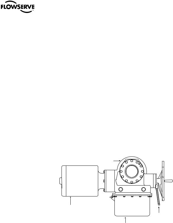
Figure 2.1 – Typical SMB (0 through 4)
Housing
 Handwheel
Motor
Declutch lever
Switch compartment
8

SMB Series/SB Series Installation and Maintenance FCD LMENIM1401-04-AQ – 01/15
2.3 Inspection and Recording
Upon receipt of the actuator:
1.Carefully remove the actuator from the shipping carton or skid. Thoroughly examine the equipment for any physical damage that may have occurred during shipment. If damaged, immediately report the damage to the transport company.
2.A nameplate is attached to each actuator. Record this information for future reference, i.e. ordering parts or obtaining further information.
2.4 Storage Procedure
NOTE: The following is our recommended storage procedure to retain maximum product integrity during storage. Failure to comply with recommended procedures will void the warranty. For longerterm storage, contact Limitorque for procedures and recommendations.
Storage (less than 1 year)
Actuators are not weatherproof until properly installed on the valve or prepared for storage.
Store actuators in a clean, dry, protected warehouse, away from excessive vibration and rapid temperature changes. If the actuators must be stored outside, they must be stored off the ground, high enough to prevent them from being immersed in water or buried by snow.
1.Position the actuator in storage with motor and switch compartment horizontal.
2.Connect the internal heaters (if supplied) or place desiccant in the switch compartment.
3.Replace all plastic caps or plugs with metal pipe plugs and ensure that all cover bolts are tight.
4.If the actuator is mounted on a valve and the stem protrudes from the actuator, a suitable stem cover must be provided.
9
flowserve.com

SMB Series/SB Series Installation and Maintenance FCD LMENIM1401-04-AQ – 01/15
3 Actuator Weights
The approximate weights of the SMB actuators and SB and SBD options are provided below:
Table 3.1 – Actuator Weights1
Actuator |
|
Weight1 |
|
Adder for SB |
|
Adder for SBD |
|||||
lb. |
|
kg |
|
lb. |
|
kg |
|
lb. |
|
kg |
|
|
|
|
|
|
|
||||||
SMB-000 |
|
|
62 |
|
N/A |
|
N/A |
|
N/A |
|
N/A |
135 |
|
|
|
|
|
||||||
|
|
|
|
|
|
|
|
|
|
|
|
SMB-00 |
200 |
|
90 |
|
65 |
|
30 |
|
100 |
|
46 |
|
|
|
|
|
|
|
|
|
|
|
|
SMB-0 |
350 |
|
159 |
|
180 |
|
83 |
|
210 |
|
97 |
|
|
|
|
|
|
|
|
|
|
|
|
SMB-1 |
460 |
|
209 |
|
200 |
|
92 |
|
325 |
|
150 |
|
|
|
|
|
|
|
|
|
|
|
|
SMB-2 |
580 |
|
263 |
|
220 |
|
101 |
|
345 |
|
159 |
|
|
|
|
|
|
|
|
|
|
|
|
SMB-3 |
1200 |
|
553 |
|
500 |
|
230 |
|
825 |
|
380 |
|
|
|
|
|
|
|
|
|
|
|
|
SMB-4 |
2020 |
|
916 |
|
795 |
|
366 |
|
1285 |
|
591 |
|
|
|
|
|
|
|
|
|
|
|
|
SMB-5&5T |
3375 |
|
1531 |
|
N/A |
|
N/A |
|
N/A |
|
N/A |
|
|
|
|
|
|
|
|
|
|
|
|
SMB-5XT |
5875 |
|
2665 |
|
N/A |
|
N/A |
|
N/A |
|
N/A |
|
|
|
|
|
|
|
|
|
|
|
|
Note 1: With the largest motor, no integral controls, and standard compartment cover.
10
SMB Series/SB Series Installation and Maintenance FCD LMENIM1401-04-AQ – 01/15
4 Installation Instructions
4.1 Safety Precautions
cc WARNING: Read this Installation and Maintenance Manual carefully and completely before
attempting to install, operate, or troubleshoot the Limitorque actuator. |
|
cc WARNING: Be aware of electrical hazards. Turn off incoming power before working on the |
|
actuator and before opening the switch compartment. |
|
cc WARNING: Potential HIGH PRESSURE vessel — be aware of high-pressure hazards associated |
|
with the attached valve or other actuated device when installing or performing maintenance on |
|
the actuator. Do not remove the actuator mounting bolts from the valve or actuated device unless |
|
the valve or device stem is secured or there is no pressure in the line. |
|
cc WARNING: For maintenance and/or disassembly of the actuator while installed on the valve, |
|
ensure that the actuator is not under thrust or torque load. If the valve must be left in service, the |
|
valve stem must be locked in such a way as to prevent any movement of the valve stem. |
|
cc WARNING: Do not attempt to remove the spring cartridge cap, housing cover, or stem nut |
|
locknut from the actuator while the valve or actuated device is under load. |
|
cc WARNING: Do not manually operate the actuator with devices other than the installed handwheel |
|
and declutch lever. Using force beyond the ratings of the actuator and/or using additive force |
|
devices such as cheater bars, wheel wrenches, pipe wrenches, or other devices on the actuator |
|
handwheel or declutch lever may cause serious personal injury and/or damage to the actuator |
|
and valve. |
|
cc WARNING: Do not exceed any design limitations or make modifications to this equipment |
|
without first consulting Limitorque. |
|
cc WARNING: Actuators equipped with electrical devices (motors, controls) requiring field wiring |
11 |
must be wired and checked for proper operation by a qualified tradesman. |
|
cc WARNING: Use of the product must be suspended any time it fails to operate properly.
flowserve.com

SMB Series/SB Series Installation and Maintenance FCD LMENIM1401-04-AQ – 01/15
aa CAUTION: Do not use oversized motor overload heaters. Instead, look for the cause of the overload.
aa CAUTION: Do not operate the valve under motor operation without first setting or checking the limit switch setting and motor direction.
aa CAUTION: Do not force the declutch lever into the motor operation position. The lever returns to this position automatically when the motor is energized.
aa CAUTION: Do not depress the declutch lever during motor operation to stop valve travel.
aa CAUTION: Do not use replacement parts that are not genuine Flowserve Limitorque parts, as serious personal injury and/or damage to the actuator and valve may result.
aa CAUTION: Do not lift actuator/gearbox or actuator/valve combinations with only the eye bolts in the SMB actuator. These eye bolts are designed for lifting the SMB actuator only.
aa CAUTION: Do not lift the actuator by the handwheel
4.2 Safety Practices
The following check points should be performed to maintain safe operation of the SMB or SB actuator:
•Eye bolts in SMB and SB actuators are designed for lifting only the actuator and not associated gearboxes or valves.
•Mount the actuator with the motor in a horizontal plane, if possible.
•Keep the switch compartment clean and dry.
•Keep the valve stem clean and lubricated.
•Set up a periodic operating schedule for infrequently used valves.
•Verify all actuator wiring is in accordance with the applicable wiring diagram.
•Carefully check for correct motor rotation direction. If the valve closes when open button is pushed, the motor leads may have to be reversed.
•Verify the stem nut is secured tightly by the locknut and that the top thread of the locknut is crimped or staked in two places.
•Use a protective stem cover. Check valve stem travel and clearance before mounting covers on rising stem valves.
4.3 Actuator Preparation
Replace all molded plastic conduit and top protectors (installed for shipping purposes only) with metal pipe plugs when installation wiring is complete.
12

SMB Series/SB Series Installation and Maintenance FCD LMENIM1401-04-AQ – 01/15
4.3.1 Mounting Base
Table 4.1 – Mounting Base Dimensions
Mounting Holes |
|
Tap Dimensions |
||
Actuator |
Quantity |
Standard |
Optional |
|
|
|
|
|
|
SMB-000 |
|
4 |
5⁄16-18 UNC x .63" deep |
N/A |
SMB-00 |
|
4 |
5⁄8-11 UNC x 1.13" deep |
M16-2 x 29 mm deep |
SMB-0 |
|
4 |
3/4-10 UNC x 1.00" deep |
M20-2.5 x 26 mm deep |
|
|
|
|
|
SMB-1 |
|
8 |
5⁄8-11 UNC x 1.00" deep |
M16-2 x 26 mm deep |
SMB-2 |
|
8 |
3/4-10 UNC x 1.13" deep |
M20-2.5 x 29 mm deep |
|
|
|
|
|
SMB-3 |
|
8 |
7⁄8-9 UNC x 1.75" deep |
M30-3.5 x 45 mm deep |
SMB-4 |
|
8 |
11/4-7 UNC x 2.00" deep |
M36-4 x 64 mm deep |
|
|
|
|
|
SMB-5 |
|
12 |
11/2-6 UNC x 3.00" deep |
N/A |
|
|
|
|
|
SMB-5T |
|
16 |
1-8 UNC x 2.00" deep |
N/A |
|
|
|
|
|
SMB-5XT |
|
16 |
Consult Factory |
N/A |
|
|
|
|
|
4.3.2 Stem Acceptance
Table 4.2 – Maximum Stem Acceptance
Two-piece nut design (drive sleeve & stem nut) Max threaded |
|
Max bore & keyway |
||||
Actuator |
inch |
mm |
|
inch |
|
mm |
SMB-000 |
|
35 |
|
1.125 w/ 1/4 x 3⁄32 |
|
26.0 w/ 8x3.5 |
1.375 |
|
|
||||
SMB-00 |
1.75 |
44 |
|
1.500 w/ 3⁄8 x 1⁄8 |
|
37.0 w/ 10x4 |
SMB-0 |
2.375 |
60 |
|
1.875 w/ 1/2 x 3⁄16 |
|
48.0 w/ 14x4.5 |
SMB-1 |
2.875 |
73 |
|
2.438 w/ 5⁄8 x 7⁄32 |
|
62.0 w/ 18x5.5 |
SMB-2 |
3.5 |
89 |
|
2.875 w/ 3/4 x 1/4 |
|
73.0 w/ 20x6 |
|
|
|
|
|
|
|
SMB-3 |
5 |
127 |
|
4.250 w/ 1.0 x 3⁄8 |
|
108.0 w/ 28x8 |
SMB-4 |
5 |
127 |
|
4.500 w/ 1.0 x 1/2 |
|
114.0 w/ 32x9 |
|
|
|
|
|
|
|
SMB-5 |
6.25 |
159 |
|
5.250 w/ 11/4 x 7⁄16 |
|
133.0 w/ 36x10 |
SMB-5T |
N/A |
N/A |
|
6.000 w/1 1/2 x 1/2 |
|
152.0 w/ 40x11 |
|
|
|
|
|
|
|
SMB-5XT |
N/A |
N/A |
|
10.000 w/ 11/4 x 5/8 |
|
N/A |
SB-00 |
1.25 |
32 |
|
|
|
|
|
|
|
|
|
|
|
SB-0 |
2.375 |
60 |
|
|
|
|
|
|
|
|
|
|
|
SB-1 |
2.625 |
66 |
|
|
|
|
|
|
|
|
|
|
|
SB-2 |
3.50 |
89 |
|
|
|
|
|
|
|
|
|
|
|
SB-3 |
4.00 |
102 |
|
|
|
|
|
|
|
|
|
|
|
SB-4 |
5.00 |
127 |
|
|
|
|
|
|
|
|
|
|
|
13
flowserve.com
SMB Series/SB Series Installation and Maintenance FCD LMENIM1401-04-AQ – 01/15
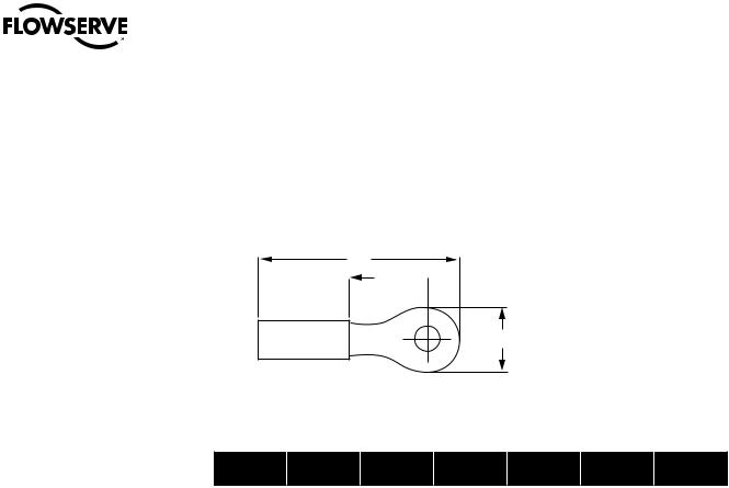
4.3.3 Terminal Connections
Wiring connections to the SMB geared limit switch, torque switch, and Marathon terminal strips are to be made using ring-tongue terminals* as shown below:
Figure 4.1 – Wiring Connections
A
C 
B
Table 4.3– Terminal Connections
AWG |
Screw Hole |
Insulation |
|
Thomas & |
|
A |
|
B |
|
C |
|
Betts P/N |
|
|
|
||||||
|
|
|
|
|
|
|
|
|
|
|
22-16 |
|
Vinyl |
|
18RA-10 |
|
.97 |
|
.31 |
|
.27 |
#10 |
|
|
|
|
||||||
|
|
|
|
|
|
|
|
|
|
|
18-14 |
#10 |
Vinyl |
|
14RB-10 |
|
.97 |
|
.31 |
|
.27 |
|
|
|
|
|
|
|
|
|
|
|
12-10 |
#10 |
Vinyl |
|
14RC-10 |
|
1.06 |
|
.31 |
|
.27 |
|
|
|
|
|
|
|
|
|
|
|
Note: Limit switch and torque switch contacts are rated 300 volts per NEMA ICS-2
Terminals are to be crimped using Thomas & Betts crimping tool WT112M or ERG4001.
Manufacturer: *Thomas and Betts or equal
4.4 Setting The Limit Switch
cc WARNING: Disconnect all incoming power before opening or replacing the limit switch compartment cover.
aa CAUTION: When wiring control circuits, distinguish between “normally open” and “normally closed” terminals on the geared limit switch.
aa CAUTION: Do NOT attempt to repair the limit switch gear box. Replace entire limit switch gear box.
aa CAUTION: Do NOT use abrasive cloth to clean the silver contacts on the limit switch. Contacts should be burnished using appropriate burnishing tool.
aa CAUTION: Before motor operation, reset the geared limit switch if the actuator has been dismantled or removed from the valve.
NOTE: Clean the limit switch cover thoroughly and apply a thin coat of grease on machined flange surfaces before mounting on an explosion proof actuator.
14

SMB Series/SB Series Installation and Maintenance FCD LMENIM1401-04-AQ – 01/15
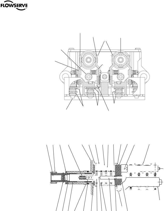
4.4.1 Two-Train Geared Limit Switch
The rotor-type, two-train geared limit switch employs two rotors. Each rotors contains four contacts. When the rotor is properly set to trip at the desired position, two of these contacts open electric circuits and two of the contacts close electric circuits. One rotor is normally set to trip at the full open position of the valve, and the other rotor is normally set to trip at the full close position of the valve.
Each rotor may be adjusted independently of the other:
•First rotor—one circuit is used to open the “open” holding coil circuit of the motor controller, one circuit is used to control the “open” indicating light.
•Second rotor—one circuit is used to open the “close” holding coil circuit of the motor controller, one circuit is used to control the “closed” indicating light.
For the geared limit switches to trip at any desired position, follow the setting procedure below.
Piece numbers refer to Figure 4.2 and Table 4.4.
1.Verify all power is OFF.
2.Using the handwheel, manually open the valve to the full open position. See Section 5.2 Manual Operation. Note the direction of rotation of the Intermittent Gear Shaft (piece #42), located over the Rotor (piece #49) to be set.
3.Using a screwdriver, turn the Set Rod (piece #48) clockwise until it reaches a stop position.
4.If the Rotor (piece #49) you are setting has not turned 90° to open the contacts that should trip open at this position, insert screwdriver on the Intermittent Gear Shaft (piece #42). Turn in the direction noted in Step No. 4 until the Rotor (piece #49) turns and opens the contacts to be set.
5.If the Rotor (piece #49) has turned so that the contacts are already open, turn the Intermittent Gear Shaft (piece #42) in the opposite direction as previously noted in Step No. 4 until the contacts close. Turn the Intermittent Gear Shaft (piece #42) slightly in the direction noted in Step No. 4 until the contacts open. The Rotor (piece #49) is set at the correct position for contact opening.
Note: In the contact “Close” position, ensure a gap exists between the contact finger and the L-bracket as seen in figure 4.2
6.Back off the Set Rod (piece #48) until it stops. Place the screwdriver on the Intermittent Gear Shaft (piece #42) to ensure that the shaft is tight and will not rotate. Do not force.
7.Close the valve completely. Repeat Step No. 1 through 6 to set the tripping position for the other Rotor (piece #49).
15
flowserve.com
SMB Series/SB Series Installation and Maintenance FCD LMENIM1401-04-AQ – 01/15
Figure 4.2 – Two-Train Geared Limit Switch – Rotor-Type
63
Contact Finger |
56 |
|
62 |
42
GAP
GAP
65 |
67 |
66 |
|
||
64 |
|
L-Bracket |
|
|
2 |
3 |
10 |
5 |
1 |
|
|
52 |
|
44 |
46 |
|
43 |
47 |
|
|
|
|
|
|
|
|
|
51 |
|
|
|
|
|
41 |
50 |
|
|
|
|
|
|
49 |
|
|
|
|
|
||||||||||||||||||||||||||||||||||||||||||||||||||||||||||||||||||||||||||
|
|
|
|
|
|
|
|
|
|
|
|
|
|
|
|
|
|
|
|
|
|
|
|
|
|
|
|
|
|
|
|
|
|
|
|
|
|
|
|
|
|
|
|
|
|
|
|
|
|
|
|
|
|
|
|
|
|
|
|
|
|
|
|
|
|
|
|
|
|
|
|
|
|
|
|
|
|
|
|
|
|
|
|
|
|
|
|
|
|
|
|
|
|
|
|
|
|
|
|
|
|
|
|
|
|
|
|
|
|
|
|
|
|
|
|
|
|
|
|
|
|
|
|
|
|
|
|
|
|
|
|
|
|
|
|
|
|
|
|
|
|
|
|
|
|
|
|
|
|
|
|
|
|
|
|
|
|
|
|
|
|
|
|
|
|
|
|
|
|
|
|
|
|
|
|
|
|
|
|
|
|
|
|
|
|
|
|
|
|
|
|
|
|
|
|
|
|
|
|
|
|
|
|
|
|
|
|
|
|
|
|
|
|
|
|
|
|
|
|
|
|
|
|
|
|
|
|
|
|
|
|
|
|
|
|
|
|
|
|
|
|
|
|
|
|
|
|
|
|
|
|
|
|
|
|
|
|
|
|
|
|
|
|
|
|
|
|
|
|
|
|
|
|
|
|
|
|
|
|
|
|
|
|
|
|
|
|
|
|
|
|
|
|
|
|
|
|
|
|
|
|
|
|
|
|
|
|
|
|
|
|
|
|
|
|
|
|
|
|
|
|
|
|
|
|
|
|
|
|
|
|
|
|
|
|
|
|
|
|
|
|
|
|
|
|
|
|
|
|
|
|
|
|
|
|
|
|
|
|
|
|
|
|
|
|
|
|
|
|
|
|
|
|
|
|
|
|
|
|
|
|
|
|
|
|
|
|
|
|
|
|
|
|
|
|
|
|
|
|
|
|
|
|
|
|
|
|
|
|
|
|
|
|
|
|
|
|
|
|
|
|
|
|
|
|
|
|
|
|
|
|
|
|
|
|
|
|
|
|
|
|
|
|
|
|
|
|
|
|
|
|
|
|
|
|
|
|
|
|
|
|
|
|
|
|
|
|
61
|
|
|
|
|
|
|
|
|
|
|
|
68 |
|
|
16 |
9 |
11 |
6 |
8 |
7 |
55 |
4 |
58 |
45 |
48 |
53 |
69 |
54 |
|
71 |
||||||||||||||
|
|
|
|
|
|
|
|
|
|
|
|
|

SMB Series/SB Series Installation and Maintenance FCD LMENIM1401-04-AQ – 01/15
Table 4.4 – Two-Train Geared Limit Switch Parts List
Piece Description
1Cartridge
2Drive Sleeve and Shaft
3Drive Pinion
4Drive Pinion (Secondary)
5Declutch Spring
6Bushing
7O-Ring
8Pin
9Groove Pin
10Washer
11Oil Seal
41Gear Frame
42Intermittent Gear Shaft
43Intermittent Pinion Shaft
44Geared Limit Frame Cover
45Intermittent Gear
46Intermittent Pinion
47Stem Spur Pinion
48Set Rod
49Rotor
50Groove Pin
51Cover Gasket
52Long Fillet Head Machine Screw
53O-Ring
54Setting Rod Bushing
55Gear Frame Gasket
56Insert (Rotor)
57O-Ring (For Intermittent Gear Shaft piece #42) (Not shown)
58Groove Pin
61Finger Base
62Right Hand Finger Assembly
63Left Hand Finger Assembly
64Long Hex Head Machine Screw
65Lockwasher
66Hex Nut
67Washer
68Long Fillet Head Cap Screw
69Internal Tooth Lockwasher
71 |
Flat Washer |
17
flowserve.com
SMB Series/SB Series Installation and Maintenance FCD LMENIM1401-04-AQ – 01/15
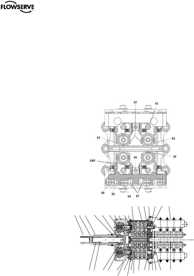
4.4.2 Four-Train Geared Limit Switch
The rotor-type, four-train geared limit switch employs four rotary drum switches. Each rotary drum switch contains four contacts. When the rotor is properly set to trip at the desired position, two of these contacts open electric circuits and two of the contacts close electric circuits. One rotor is set to trip at the full open position of the valve, and one rotor is set to trip at the full close position of the valve. The other two rotors are set at some intermediate position depending on the application.
For the geared limit switches to trip at any desired position, follow the steps in Section 4.4.1,
Two-Train Geared Limit Switch, with the exception that the piece numbers refer to Figure 4.3 and
Table 4.5.
NOTE: The upper Set Rod (piece #48) allows adjustment of the two adjacent upper rotors, and the lower Set Rod (piece #48) allows adjustment of the two adjacent lower rotors.
Figure 4.3 – Four-Train Geared Limit Switch – Rotor Type
46 43 53 41 54 48 61
25 |
26 |
21 |
35 |
34 |
28 |
27 |
|
|
30 |
29 |
|
|
|
|||||||||||||||||||||
|
|
|
|
|
|
|
|
|
|
|
|
|
|
|
|
|
|
|
|
|
|
|
|
|
|
|
|
|
|
|
|
|
|
|
|
|
|
|
|
|
|
|
|
|
|
|
|
|
|
|
|
|
|
|
|
|
|
|
|
|
|
|
|
|
|
|
|
|
|
|
|
|
|
|
|
|
|
|
|
|
|
|
|
|
|
|
|
|
|
|
|
|
|
|
|
|
|
|
|
|
|
|
|
|
|
|
|
|
|
|
|
|
|
|
|
|
|
|
|
|
|
|
|
|
|
|
|
|
|
|
|
|
|
|
|
|
|
|
|
|
|
|
|
|
|
|
|
|
|
|
|
|
|
|
|
|
|
|
|
|
|
|
|
|
|
|
|
|
|
|
|
|
|
|
|
|
|
|
|
|
|
|
|
|
|
|
|
|
|
|
|
|
|
|
|
|
|
|
|
|
|
|
|
|
|
|
|
|
|
|
|
|
|
|
|
|
|
|
|
|
|
|
|
|
|
|
|
|
|
|
|
|
|
|
|
|
|
|
|
|
|
|
|
|
|
|
|
|
|
|
|
|
|
|
|
|
|
|
|
|
|
|
|
|
|
|
|
|
|
|
|
|
|
|
|
|
|
|
|
|
|
|
|
|
|
|
|
|
|
|
|
|
|
|
|
|
|
|
|
|
|
|
|
|
|
|
|
|
|
|
|
|
|
|
|
|
|
|
|
|
|
|
|
|
|
|
|
|
|
|
|
|
|
|
|
|
|
|
|
|
|
|
|
|
|
|
|
|
|
|
|
|
|
|
|
|
|
|
|
|
|
|
|
|
|
|
|
|
|
|
|
|
|
|
|
|
|
|
|
|
|
|
|
|
|
|
|
|
|
|
|
|
|
|
|
|
|
|
|
|
|
|
|
|
|
|
|
|
|
|
|
|
|
|
|
|
|
|
|
|
|
|
|
|
|
|
|
|
|
|
|
|
|
|
|
|
|
|
|
|
|
|
|
|
|
|
|
|
|
|
|
|
|
|
|
|
|
|
|
|
|
|
|
|
|
|
|
|
|
|
|
|
|
|
|
|
|
|
|
|
|
|
|
|
|
|
|
|
|
18
22 |
23 |
26 |
24 |
31 |
55 |
44 |
58 |
45 |
42 68 |
57 47 50 |
49 |
|
|
|
|
32 |
|
52 |
|
69 |
|
|
|
|
|
|
|
|
|
|
|
|
71 |
|
|
01-472--00077-3-3

SMB Series/SB Series Installation and Maintenance FCD LMENIM1401-04-AQ – 01/15
Table 4.5 – Four-Train Geared Limit Switch Parts List
Piece Description
21Cartridge
22Oilite Bushing
23Drive Shaft
24Drive Pinion (Internal)
25Helical Pinion
26Groove Pin
27Drive Sleeve and Gear
28Declutch Spring
29Drive Pinion Spur
30Pin
31Cartridge Gasket
32Cartridge Mounting Plate
33Long Socket Head Cap Screw and Lockwasher
34O-Ring
35O-Ring
36Fillet Head Cap Screw and Lockwasher
41Gear Frame
42Intermittent Gear Shaft
43Intermittent Pinion Shaft
44Geared Limit Frame Cover
45Intermittent Gear
46Intermittent Pinion
47Stem Spur Pinion
48Set Rod
49Rotor
50Groove Pin
51Cover Gasket
52Long Fillet Head Machine Screw
53O-Ring
54Setting Rod Bushing
55Gear Frame Gasket
56Insert (Rotor)
57O-Ring
58Groove Pin
61Finger Base
62Right Hand Finger Assembly
63Left Hand Finger Assembly
64Long Hex Head Cap Screw
65Lockwasher
66Hex Nut
67Washer
68Long Fillet Head Cap Screw
69 |
Internal Tooth Lockwasher |
19 |
71 |
Flat Washer |
|
flowserve.com

SMB Series/SB Series Installation and Maintenance FCD LMENIM1401-04-AQ – 01/15
4.5 Setting Torque Switch
The torque switch is designed to protect the actuator in open and close directions.
cc WARNING: Disconnect all incoming power before working on the torque switch.
cc WARNING: Do not attempt to remove either the spring cartridge cap or the housing cover from the actuator while the valve is torque-seated.
aa CAUTION: Do not use abrasive cloth to clean the contacts on the torque switch.
aa CAUTION: A maximum stop setting plate is furnished on all actuators. Do not exceed this maximum setting without consulting Limitorque.
NOTE: See Section 4.3.3 for wiring connection requirements.
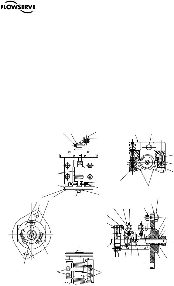
4.5.1 SMB-000 “Cam Style” Double Torque Switch
NOTE: Torque settings must be made with the switch mounted in the actuator.
Piece numbers correspond to Figure 4.4 and Table 4.6.
To set the torque switch:
1.Verify all electric power is OFF.
2.Loosen Pan Head Screws (piece #30).
3.For open or close operation, set Striker (piece #25) to the required torque setting. Match the edge of the Striker with the desired number. The higher the number, the higher the torque output of the actuator.
4.Tighten Pan Head Screws (piece #30).
5.For torque seated valves, operate the valve electrically to seat the valve. Ensure tight shut-off by tripping the torque switch contacts.
20

SMB Series/SB Series Installation and Maintenance FCD LMENIM1401-04-AQ – 01/15
Figure 4.4 – SMB-000 “Cam Style” Double Torque Switch
9 |
12 |
11 |
10 |
5 |
6 |
4 |
8 |
14 |
37 |
|
|
|
|
|
7 |
|
|
|
|
5
4
3 2
1
5
4
3
2
1
38 |
|
|
|
|
|
|
|
2 |
|
|
|
39 |
|
|
|
|
|
|
|
45 |
13 |
15 |
|
|
|
|
|
|
|
|
|
|
|||
|
|
|
|
|
|
|
|
|
SECTION A-A |
||
27 |
25 |
23 |
21 |
3 |
2 |
19 |
37 |
36 |
|
|
|
|
|
|
|
A |
|
|
44 |
|
|
|
|
|
|
|
|
|
|
|
|
B |
|
|
|
42
42
VIEW B-B
A 

B
30 |
32 |
31 |
25 |
22 |
20 |
|
17 |
1 |
16 |
18 |
33 |
34 |
35 |
|
27 |
24 |
25 |
26 |
25 |
23 |
22 |
21 |
43 |
|
20 |
|
|
28 29
0101-474-474-0056-0056-4 -4
21
flowserve.com

SMB Series/SB Series Installation and Maintenance FCD LMENIM1401-04-AQ – 01/15
Table 4.6 – SMB-000 “Cam Style” Double Torque Switch Parts List
|
Piece |
Description |
|
|
|
|
1 |
Terminal Block |
|
|
|
|
2 |
Contact Block |
|
|
|
|
3 |
Contact Screw |
|
|
|
|
4 |
Finger Holder |
|
|
|
|
5 |
Finger |
|
|
|
|
6 |
Shunt |
|
|
|
|
7 |
Shunt Washer |
|
|
|
|
8 |
Rivet |
|
|
|
|
9 |
Finger Spring Stud |
|
|
|
|
10 |
Compression Spring |
|
|
|
|
11 |
Spring Cup Washer |
|
|
|
|
12 |
Cotter Pin |
|
|
|
|
13 |
Hex Head Machine Screw |
|
|
|
|
14 |
Ring Tongue Connector |
|
|
|
|
15 |
Shakeproof Lockwasher, Internal Teeth |
|
|
|
|
16 |
Torque Switch Mounting Bracket |
|
|
|
|
17 |
O-Ring |
|
|
|
|
18 |
O-Ring |
|
|
|
|
19 |
Socket Head Cap Screw |
|
|
|
|
20 |
Cam |
|
|
|
|
21 |
Torsion Spring |
|
|
|
|
22 |
Spring Mandrel |
|
|
|
|
23 |
Dial |
|
|
|
|
24 |
Shaft |
|
|
|
|
25 |
Striker |
|
|
|
|
26 |
Torque Limiting Plate |
|
|
|
|
27 |
Striker Hub |
|
|
|
|
28 |
Roll Pin |
|
|
|
|
29 |
Swage Nut |
|
|
|
|
30 |
Pan Head Screw |
|
|
|
|
31 |
Shakeproof Lockwasher, External Teeth |
|
|
|
|
32 |
Flatwasher |
|
|
|
|
33 |
Arm |
|
|
|
|
34 |
Roller |
|
|
|
|
35 |
Roller Pin |
|
|
|
|
36 |
Groove Pin |
|
|
|
|
37 |
Arc Barrier |
|
|
|
|
38 |
Pan Head Screw |
|
|
|
|
39 |
Lockwasher, External Tooth |
|
|
|
|
42 |
Spring Pin |
|
|
|
|
43 |
Cam Insert |
|
|
|
|
44 |
Bushing (For piece #16) |
|
|
|
22 |
45 |
Washer |
SMB Series/SB Series Installation and Maintenance FCD LMENIM1401-04-AQ – 01/15
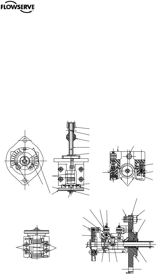
4.5.2 SMB-000 and SMB-00 “C Style” Double Torque Switch
NOTE: Torque settings must be made with the switch mounted in the actuator.
NOTE: See Section 4.3.3 for wiring connection requirements.
Piece numbers correspond to Figure 4.5 and Table 4.7.
To set the torque switch:
1.Verify all electric power is OFF.
2.For the open or close direction torque switch, loosen Machine Screw (piece #35) and set Pointer (piece #7) at the desired torque setting. The higher the number, the higher the torque output of the actuator.
3.Tighten Machine Screw (piece #35).
4.For torque seated valves, operate the valve electrically to seat the valve. Ensure tight shut-off by tripping the torque switch contacts.
Figure 4.5 – SMB-000 and SMB-00 “C Style” Double Torque Switch
5 4 3
2
1
|
23 |
8 |
|
14 |
|
1 |
|
43 |
|
|
|
|
|
44 |
|
||||
|
|
|
|
13 |
|
|
|
|
|
|
|
|
|
|
|
|
|
|
17 |
|
|
|
|
|
2 |
|
|
|
33 |
|
|
|
|
|
|
|
|
51 |
|
|
25 |
|
|
|
|
|
|
|
37 |
|
5 |
|
|
30 |
27 |
|
|
|
|
|
|
|
34 |
|
|
|
4 |
|
|
|
|
|
|
|
|
|
|
||
46 |
11 |
|
31 |
25 |
|
|
|
3 |
|
|
39 |
|
|
42 |
45 |
|
|||
|
|
|
|
|
|
|
|||
|
|
|
|
27 |
29 |
16 |
47 |
|
|
|
|
|
|
27 |
|
|
|
|
20 |
|
|
|
|
36 |
|
|
|
|
25 |
|
|
|
|
48 |
|
|
|
|
|
|
|
|
|
|
|
|
|
12 |
|
|
|
|
|
6 |
|
|
|
|
|
|
3 |
|
|
|
|
|
|
|
|
|
2 |
|
|
|
|
|
|
|
|
|
1 |
|
|
|
|
|
|
|
|
|
|
|
|
9 |
|
|
|
|
|
35 |
7 |
|
|
|
28 |
15 |
10 |
22 |
21 |
|
|
|
|
||||||
39/52 |
41 |
|
|
|
|
|
|
|
|
|
|
|
18 |
|
|
|
|
|
|
|
27/50 |
|
|
|
0101-473-473-0056-0056-3-3 |
|
23 |
||
flowserve.com

SMB Series/SB Series Installation and Maintenance FCD LMENIM1401-04-AQ – 01/15
Table 4.7 – SMB-000 and SMB-00 “C Style” Double Torque Switch Parts List
|
Piece |
Description |
|
|
|
|
1 |
Terminal Block |
|
|
|
|
2 |
Contact Block |
|
|
|
|
3 |
Hex Nut - Remove and discard |
|
|
|
|
4 |
Contact Arm |
|
|
|
|
5 |
Dial |
|
|
|
|
6 |
Actuating Link |
|
|
|
|
7 |
Pointer |
|
|
|
|
8 |
Tripper Arm |
|
|
|
|
9 |
Shaft |
|
|
|
|
10 |
Contact Support |
|
|
|
|
11 |
Torque Limiter Plate |
|
|
|
|
12 |
Bushing (SMB-00 only) |
|
|
|
|
13 |
Roller |
|
|
|
|
14 |
Roller Pin |
|
|
|
|
15 |
Contact Finger |
|
|
|
|
16 |
Terminal Stud |
|
|
|
|
17 |
Compression Spring |
|
|
|
|
18 |
Torsion Spring |
|
|
|
|
20 |
Bearing |
|
|
|
|
21 |
O-Ring |
|
|
|
|
22 |
O-Ring |
|
|
|
|
23 |
Groove Pin |
|
|
|
|
25 |
Thrust Washer |
|
|
|
|
27 |
Lockwasher |
|
|
|
|
28 |
Groove Pin |
|
|
|
|
29 |
Hex Nut |
|
|
|
|
30 |
Hex Nut |
|
|
|
|
31 |
Cotter Pin |
|
|
|
|
33 |
Pan Head Machine Screw |
|
|
|
|
34 |
Hex Socket Set Screw |
|
|
|
|
35 |
Round Head Machine Screw |
|
|
|
|
36 |
Round Head Machine Screw |
|
|
|
|
37 |
Insulating Material |
|
|
|
|
39 |
Flatwasher |
|
|
|
|
41 |
Round Head Machine Screw |
|
|
|
|
42 |
Lockwasher, Internal Teeth |
|
|
|
|
43 |
Socket Head Cap Screw |
|
|
|
|
44 |
Lockwasher |
|
|
|
|
45 |
Mounting Bracket |
|
|
|
|
46 |
Dial Plate (SMB-00 only) |
|
|
|
|
47 |
Socket Head Cap Screw |
|
|
|
|
48 |
Lockwasher (SMB-000 only) |
|
|
|
24 |
49 |
Insulator (SMB-000 only) - Not Shown |
|
50 |
Lockwasher (SMB-000 only) |
|
|
|
|
51 |
Lockwasher (SMB-000 only) |
|
|
|
|
52 |
Lockwasher (SMB-000 only) |
|
|
|
SMB Series/SB Series Installation and Maintenance FCD LMENIM1401-04-AQ – 01/15
4.5.3 SMB-0 through SMB-5 Double Torque Switch
NOTE: Torque settings must be made with the switch mounted in the actuator.
NOTE: See Section 4.3.3 for wiring connection requirements.
Piece numbers correspond to Figure 4.6 and Table 4.8.
To set the torque switch:
1.Verify all electric power is OFF.
2.For the open or close direction torque switch, loosen Machine Screw (piece #35) and set Pointer (piece #7) at the desired torque setting. The higher the number, the higher the torque output of the actuator.
3.Tighten Machine Screw (piece #35).
4.For torque seated valves, operate the valve electrically to seat the valve. Ensure tight shut-off by tripping the torque switch contacts.
Figure 4.6 – SMB-0 through SMB-5 Double Torque Switch
|
|
5 |
|
4 |
3 |
|
|
|
3 |
|
3 |
|
|
|
2 |
|
2 |
1 |
|
1 |
|
|
|
|
25 |
35 |
7 |
5 |
39 |
|
11 |
|
|
31
41 |
18 |
|
27 |
||
|
|
8 |
|
|
|
|
23 |
|
|
43 |
|
12 |
|
|
|
|
1 |
|
44 |
|
|
13 |
|
||
|
|
|
|
|
|
25 |
|
|
|
|
|
|
|
17 |
|
2 |
|
|
33 |
|
30 |
|
|
37 |
|
|
|
|
|
|
34 |
|
|
4 |
|
25 |
|
|
45 |
|
|
|
|
|
39 |
29 |
16 |
42 |
|
27 |
47 |
3 |
||
|
|
|
27 |
20 |
|
|
36 |
|
6 |
|
9 
28 |
15 |
10 |
22 |
21 |
25 |
|
|
|
|
|
01-473-00057-3
01-473- -3
flowserve.com

SMB Series/SB Series Installation and Maintenance FCD LMENIM1401-04-AQ – 01/15
Table 4.8 – SMB-0 through SMB-5 Double Torque Switch Parts List
Piece Description
1Terminal Block
2Contact Block
3Hex Nut - Remove and Discard
4Contact Arm
5Dial
6Actuating Link
7Pointer
8Pinion
9Shaft
10Contact Support
11Torque Limiter Plate
12Bushing
13Spacer
15Contact Finger
16Terminal Stud
17Compression Spring
18Torsion Spring
20Bearing
21O-Ring
22O-Ring
23Pin
25 |
Thrust Washer |
27Lockwasher
28Pin
29Hex Nut
30Hex Nut
31Cotter Pin
33Pan Head Self-Tapping Screw
34Hex Socket Set Screw
35Round Head Machine Screw
36Round Head Machine Screw
37Insulating Material
39 Flatwasher
41Round Head Machine Screw
42Lockwasher, Internal Teeth
43Socket Head Cap Screw
44Lockwasher
45Mounting Bracket
47 |
Socket Head Cap Screw |
26

SMB Series/SB Series Installation and Maintenance FCD LMENIM1401-04-AQ – 01/15
4.6 Position Indication
4.6.1 Local Position Indicator
NOTE: The local dial position indicator displays valve position. The position indicator can only be adjusted when the actuator is mounted on the valve. See Figures 7.1-7.3 (SMB-000), 7.4-7.8 (SMB00), 7.9-7.12 (SMB-0 through 4), 7.13-7.16 (SMB-5).
To set the position indicator:
1.Disconnect all incoming power and open or remove the Limit Switch Compartment Cover.
2.Place the valve in the fully “close” position.
3.Loosen the round head machine screw that holds the pointer in place, move the pointer to the “C” position, and retighten the screw.
The indicator is now set.
4.6.2Remote Position Indicator
(50 ohm or 1000 ohm Potentiometer)
The SMB or SB actuator with a potentiometer installed, transmits a 0-10 VDC output signal to a remote position indicator (meter). The potentiometer is powered by 120 VAC.
To set the potentiometer:
NOTE: The pinion has been disengaged to prevent damaging the potentiometer prior to setting the valve.
1.Set the potentiometer by turning the pinion until the desired reading is obtained.
2.Loosen the hex nut on the back of the potentiometer and slide the potentiometer in the direction of the idler pinion until the pinions are engaged.
3.Do not force the engagement of the pinions.
4.Retighten the hex nut on the back of the potentiometer.
5.Do not engage the pinion until the actuator and valve positions have been set.
To calibrate the potentiometer: |
|
|
1. |
Position the valve at 50% of full travel. |
|
2. |
Read the resistance from the wiper to either end of the potentiometer. |
|
3. |
To set the potentiometer to the proper value, loosen the set screw on the potentiometer shaft |
|
|
pinion and rotate the potentiometer shaft to a reading of ~500 ohms for the 1000-ohm potenti- |
|
|
ometer, or ~25 ohms for the 50-ohm potentiometer. |
|
4. |
Tighten the set screw. |
|
5. |
Run the actuator to the fully CLOSED position. |
|
6. |
Adjust the CLOSED position setting to a value at or above 0 ohms. |
|
7. |
Run the actuator to the fully OPEN position. |
27 |
flowserve.com

SMB Series/SB Series Installation and Maintenance FCD LMENIM1401-04-AQ – 01/15
8.Adjust the OPEN position setting to a value at or below 1000 ohms for the 1000-ohm potentiometer; at or below 50 ohms for the 50-ohm potentiometer.
9.Repeat steps 5 through 8 and fine-tune as necessary.
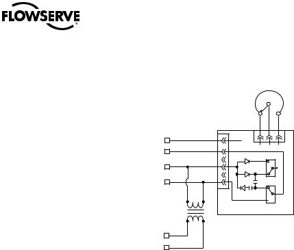
4.6.3Remote Position Indicator (Resistance-to-Current Signal Converter)
The SMB or SB actuator with a signal converter installed transmits a 4-20 mA output signal to a remote position indicator (meter). The signal converter responds to the input of a 1000-ohm potentiometer and can be powered by 24 VDC or 120 VAC for the older version R/I converter; or 18 VDC, 24 VDC, or 120 VDC for the PT20SD style R/I converter.
To set the R/I signal converter:
NOTE: The pinion has been disengaged to prevent damaging the potentiometer prior to setting the valve.
1.Set the potentiometer by turning the pinion until the desired reading is obtained.
2.Loosen the hex nut on the back of the potentiometer and slide the potentiometer in the direction of the idler pinion until the pinions are engaged.
3.Do not force the engagement of the pinions.
4.Retighten the hex nut on the back of the potentiometer.
5.Do not engage the pinion until the actuator and valve positions have been set.
To calibrate the R/I signal converter:
1.Position the valve at 50% of full travel.
2.Read the ohms from the wiper to either end of the potentiometer.
3.To set the potentiometer to the proper value, loosen the set screw on the potentiometer shaft pinion and rotate the potentiometer shaft to a reading of 500 ohms.
4.Tighten the set screw.
5.Run the actuator to the fully CLOSED position.
6.Adjust the ZERO control to an output of 4 mA.
7.Run the actuator to the fully OPEN position.
8.Adjust the SPAN control to an output of 20 mA.
9.Repeat steps 5 through 8 to fine-tune as necessary.
28
SMB Series/SB Series Installation and Maintenance FCD LMENIM1401-04-AQ – 01/15
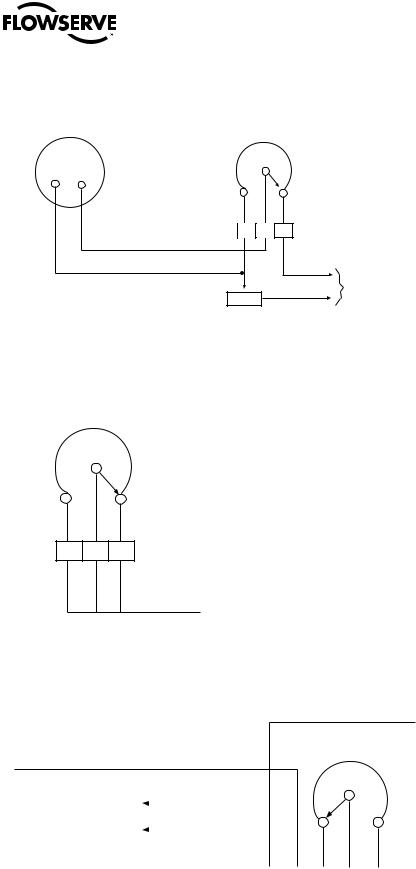
Figure 4.7 – Typical Connection for a 50-ohm Potentiometer
Remote position indicator
0-10 volts full scale deflection
Voltmeter
type
25 Watt, 50 OHM Potentiometer type variable resistor mounted in SMB/SB housing
P1 |
P2 |
P3 |
RES
175 Watt, 2500 ohm Adjustable resistor
to be located adjacent to remote position indicator for voltage adjustment
Figure 4.8 – Typical Connection for a 1000-ohm Potentiometer
Potentiometer 1000 ohm 2 Watt in limit switch housing
Control voltage range 110 volts to 480 volts
(CCW) (CW)
P1 P2 P3
 To customer’s equipment
Potentiometer slider rotates toward counter clockwise (CCW) terminal as valve opens
Figure 4.9 – Typical Connection for R/I Signal Converter (Older Version)
|
|
|
|
|
|
|
|
|
|
|
|
|
POT |
|
|||
|
|
|
|
|
|
|
|
|
|
|
1000 |
ohm |
|
||||
|
|
|
|
|
|
|
|
|
|
|
|
|
P2 |
|
|||
4-20 mA |
|
|
|
|
|
|
|
|
|
|
|
|
|
|
|||
|
|
|
|
|
|
|
|
|
|
|
|
|
|
||||
Output Signal |
|
|
|
|
|
|
|
|
|
|
|
|
|
||||
|
|
|
|
|
90 |
|
C |
C |
P1 |
|
P3 |
|
|||||
|
91 |
|
|
|
|
||||||||||||
|
|
(–) |
|
(+) |
|
L2 L1 |
|
|
|
|
|
|
|
||||
|
|
|
|
|
|
|
|
|
|
|
|
|
|
|
|
|
|
|
|
91 |
|
90 |
|
CL2 |
CL1 |
|
P1 |
P2 |
|
P3 |
|
|
|||
|
|
|
|
|
|
|
|
|
|
|
|
|
|
|
|
||
|
|
|
(–) |
(+) |
|
|
|
|
PC Board |
|
29 |
||||||
|
|
|
|
|
|
|
|
|
|
|
|
Connection |
|
|
|||
|
|
|
R to I Signal Converter |
|
|
|
|
||||||||||
|
|
|
|
|
|
|
|
|
|
|
|
|
|
|
|
|
|
flowserve.com
SMB Series/SB Series Installation and Maintenance FCD LMENIM1401-04-AQ – 01/15
Figure 4.10 – Typical Connection for PT20SD R/I Converter
(+)
4-20 mA
Output (–) Signal
(+)
24 VDC or
18 VAC
See comments (–) under Section
4.6.3,
BLU
BLU
|
|
|
|
POT |
|
|
|
|
1000 |
ohm |
|
|
|
|
|
(S) |
|
|
|
|
(CCW) |
|
(CW) |
|
|
|
BLK |
BRN |
RED |
Black |
1 |
(+)mA |
1 |
2 3 |
|
|
|
|
|||
Brown |
2 |
(–)mA |
CCW |
S CW |
|
|
3 |
|
|
|
|
Orange |
4 |
+V |
|
|
1 |
|
|
2 |
|||
|
5 |
|
|
|
|
|
|
|
|
3 |
|
|
|
|
|
|
|
Green |
6 |
|
|
LK2 |
|
|
|
|
|
AC |
1 |
|
|
|
|
2 |
|
18V |
|
COM |
|
DC |
|
 3
3
LK3
Signal Converter
115V
4.7 Additional Electrical Components
4.7.1 Reversing Starter
The reversing starter electrically changes the operation of the electric motor from one direction of rotation to the other. The starter consists of two contactors mounted on a common base and mechanically interlocked.
Each contactor consists of the following:
•three normally open power contacts
•one normally open circuit holding contact
•one normally closed interlock
•one magnetic holding coil.
The starter can be provided two ways:
•Mounted within the actuator limit switch compartment
•Supplied in a separate enclosure
4.7.2 Overload Relays
Overload relays de-energize the holding coils of the reversing starter, which open the power contacts to de-energize the electric motor. The relays function at a predetermined current value and can reset either automatically or manually as follows:
•Reset automatically if mounted as detailed in Figure 4.11.
•Reset manually if the reversing starter is furnished separately.
The relays are sized in accordance with full load (running) motor current.
30
 Loading...