


fanuc 30iA, 300iA, 300is A, 31iA5, 310iA5 Operator Manual
...FANUC Series 30*/300*/300*s-MODEL A FANUC Series 31*/310*/310*s-MODEL A5 FANUC Series 31*/310*/310*s-MODEL A FANUC Series 32*/320*/320*s-MODEL A
Dual Check Safety
OPERATOR’S MANUAL
B-64004EN/02

•No part of this manual may be reproduced in any form.
•All specifications and designs are subject to change without notice.
The export of this product is subject to the authorization of the government of the country from where the product is exported.
In this manual we have tried as much as possible to describe all the various matters. However, we cannot describe all the matters which must not be done, or which cannot be done, because there are so many possibilities.
Therefore, matters which are not especially described as possible in this manual should be regarded as ”impossible”.
This manual contains the program names or device names of other companies, some of which are registered trademarks of respective owners. However, these names are not followed by or in the main body.

B-64004EN/02 |
DEFINITION OF WARNING, CAUTION, AND NOTE |
DEFINITION OF WARNING, CAUTION, AND NOTE
This manual includes safety precautions for protecting the user and preventing damage to the machine. Precautions are classified into Warning and Caution according to their bearing on safety. Also, supplementary information is described as a Note. Read the Warning, Caution, and Note thoroughly before attempting to use the machine.
 WARNING
Applied when there is a danger of the user being injured or when there is a danger of both the user being injured and the equipment being damaged if the approved procedure is not observed.
 CAUTION
Applied when there is a danger of the equipment being damaged, if the approved procedure is not observed.
NOTE
The Note is used to indicate supplementary information other than Warning and Caution.
•Read this manual carefully, and store it in a safe place.
s-1

B-64004EN/02 |
TABLE OF CONTENTS |
TABLE OF CONTENTS
DEFINITION OF WARNING, CAUTION, AND NOTE ................................. |
s-1 |
||||
1 |
OVERVIEW |
............................................................................................. |
|
1 |
|
|
1.1 |
DIRECTIVE AND STANDARDS .................................................................... |
3 |
||
|
|
1.1.1 |
Directives .................................................................................................................. |
3 |
|
|
|
1.1.2 |
Related Safety Standards .......................................................................................... |
3 |
|
|
|
1.1.3 Risk Analysis and Evaluation................................................................................... |
3 |
||
|
1.2 |
DEFINITION OF TERMS............................................................................... |
4 |
||
|
|
1.2.1 General Definition of Terms .................................................................................... |
4 |
||
|
|
1.2.2 Definition of Terms Related to the Safety Function ................................................ |
4 |
||
|
1.3 |
BASIC PRINCIPLE OF DUAL CHECK SAFETY ........................................... |
5 |
||
|
|
1.3.1 Features of Dual Check Safety ................................................................................. |
5 |
||
|
|
1.3.2 Compliance with the Safety Standard (EN954-1, Category 3) ................................ |
5 |
||
|
|
|
1.3.2.1 Latent error detection and cross - check .................................................................................................. |
7 |
|
|
|
|
1.3.2.2 Safety monitoring cycle and cross - check cycle ..................................................................................... |
7 |
|
|
|
|
1.3.2.3 |
Error analysis.......................................................................................................................................... |
8 |
|
|
|
1.3.2.4 |
Remaining risks...................................................................................................................................... |
8 |
|
1.4 |
GENERAL .........................................................................INFORMATION |
10 |
||
2 |
SYSTEM CONFIGURATION................................................................. |
12 |
|||
3 |
SAFETY FUNCTIONS........................................................................... |
14 |
|||
|
3.1 |
APPLICATION ...............................................................................RANGE |
15 |
||
|
3.2 |
BEFORE ...............................................USING THE SAFETY FUNCTION |
17 |
||
|
|
3.2.1 ................................Important Items to Check Before Using the Safety Function |
17 |
||
|
|
3.2.2 ................................................................MCC off Test of the Safe Stop Function |
17 |
||
|
3.3 |
STOP........................................................................................................... |
|
|
18 |
|
|
3.3.1 ...................................................................................Stopping the Spindle Motor |
18 |
||
|
|
3.3.2 ......................................................................................Stopping the Servo Motor |
18 |
||
|
|
3.3.3 .............................................................................................................. |
Stop States |
19 |
|
|
3.4 |
SAFE- .............................................RELATED I/O SIGNAL MONITORING |
20 |
||
|
3.5 |
EMERGENCY ...................................................................................STOP |
29 |
||
|
3.6 |
SAFE ......................................................................SPEED MONITORING |
30 |
||
|
3.7 |
SAFE ...............................................MACHINE POSITION MONITORING |
32 |
||
|
3.8 |
MCC OFF ..........................................................................................TEST |
34 |
||
|
3.9 |
SAFETY ..................................................POSITION SWITCH FUNCTION |
35 |
||
|
3.10 SAFETY ...........................RELATED PARAMETERS CHECK FUNCTION |
37 |
|||
c-1
TABLE OF CONTENTS |
B-64004EN/02 |
|||
|
3.11 |
PARAMETER LOCK FUNCTION ................................................................ |
37 |
|
|
3.12 |
SEFETY POSITION ERROR MONITORING FUNCTION ........................... |
38 |
|
|
3.13 |
AMPLIFIER CIRCUIT MONITORING FUNCTION....................................... |
39 |
|
|
3.14 |
SAFETY BRAKE SIGNAL OUTPUT FUNCTION ........................................ |
40 |
|
|
3.15 |
CPU SELF TEST FUNCTION...................................................................... |
41 |
|
|
3.16 |
RAM CHECK FUNCTION............................................................................ |
42 |
|
|
3.17 |
CRC CHECK FUNCTION............................................................................ |
42 |
|
|
3.18 |
SAFE STOP MONITORING ........................................................................ |
43 |
|
4 |
INSTALLATION .................................................................................... |
44 |
||
|
4.1 |
OVERALL CONNECTION DIAGRAM ......................................................... |
45 |
|
5 |
I/O SIGNALS |
......................................................................................... |
47 |
|
|
5.1 |
OVERVIEW ................................................................................................. |
48 |
|
|
5.2 |
SIGNAL ADDRESS ..................................................................................... |
49 |
|
|
5.3 |
SIGNALS ..................................................................................................... |
53 |
|
|
5.4 |
GENERAL PURPOSE I/O SIGNAL ............................................................. |
71 |
|
|
5.5 |
NOTE ON MULTI PATH CONTROL............................................................ |
72 |
|
|
|
5.5.1 Machine Group And Multi Path Control................................................................ |
72 |
|
6 |
PARAMETERS...................................................................................... |
74 |
||
|
6.1 |
OVERVIEW ................................................................................................. |
75 |
|
|
6.2 |
DATA TYPE................................................................................................. |
76 |
|
|
6.3 |
REPRESENTATION OF PARAMETERS .................................................... |
77 |
|
|
6.4 |
STANDARD PARAMETER STTING TABLES ............................................. |
78 |
|
|
6.5 |
PARAMETERS............................................................................................ |
80 |
|
|
6.6 |
PROFIBUS-DP PARAMETER SETTINGS ................................................ |
107 |
|
7 |
START-UP........................................................................................... |
|
109 |
|
|
7.1 |
START-UP OPERATION........................................................................... |
110 |
|
|
|
7.1.1 Acceptance test and report for safety functions ................................................... |
110 |
|
|
7.2 |
START-UP OF THE SAFETY FUNCTION ................................................ |
112 |
|
|
|
7.2.1 |
Initial start-up ....................................................................................................... |
112 |
|
|
7.2.2 |
Series start-up ....................................................................................................... |
114 |
|
|
7.2.3 |
Troubleshooting ................................................................................................... |
114 |
8 |
ALARM MESSAGE............................................................................. |
115 |
||
9 |
DIAGNOSIS......................................................................................... |
|
123 |
|
|
9.1 |
MCC OFF TEST STATUS SCREEN ......................................................... |
124 |
|
|
9.2 |
CROSS CHECK DATA SCREEN .............................................................. |
125 |
|
c-2
B-64004EN/02 |
|
TABLE OF CONTENTS |
||
|
9.3 |
FLOW MONITORING SCREEN ................................................................ |
128 |
|
|
9.4 |
FEED LIMIT MONITORING SCREEN....................................................... |
129 |
|
|
9.5 |
SAFE MACHINE POSITIONING MONITORING SCREEN ....................... |
131 |
|
|
9.6 |
SAFETY POSITION ERROR MONITORING SCREEN............................. |
132 |
|
10 |
SAMPLE SYSTEM CONFIGURATION............................................... |
133 |
||
|
10.1 |
SAMPLE CONFIGURATION ..................................................................... |
134 |
|
|
10.2 |
SAMPLE CONNECTIONS......................................................................... |
135 |
|
|
|
10.2.1 |
Emergency Stop Signal (*ESP)............................................................................ |
135 |
|
|
10.2.2 |
Guard Open Request Signal (ORQ) ..................................................................... |
136 |
|
|
10.2.3 |
Test Mode Signal (OPT) ...................................................................................... |
136 |
|
|
10.2.4 |
Guard Open Inhibit Signal (*OPIHB), Monitoring Result Signal (RSVx,RSPx), |
|
|
|
|
Safety check Request Signal (*VLDVx,*VLDPs)............................................... |
137 |
|
|
10.2.5 MCC Off Signal (*MCF,*MCFVx,*MCFPs,*DCALM), MCC Contact State |
|
|
|
|
|
Signal (*SMC)...................................................................................................... |
139 |
11 |
COMPONENTS LIST .......................................................................... |
140 |
||
|
11.1 |
HARDWARE COMPONENTS ................................................................... |
141 |
|
|
|
11.1.1 |
Hardware Components for Series 30i/300i/300is-MODEL A ............................. |
141 |
|
|
11.1.2 |
Hardware Components for Other Units................................................................ |
141 |
|
11.2 |
SOFTWARE COMPONENTS.................................................................... |
144 |
|
|
11.3 |
SERVO AMPLIFIER .................................................................................. |
145 |
|
APPENDIX |
|
|
||
A Directives, Standards and Technical Conditions for 3rd Party |
|
|||
|
Servo / Spindle Motors & Encoders when Applying FANUC / |
|
||
|
GE Fanuc Dual-check Safety ............................................................ |
153 |
||
|
A.1 |
GENERAL ................................................................................................. |
154 |
|
|
A.2 MANDATORY STANDARDS AND DIRECTIVES...................................... |
155 |
||
|
A.3 |
SPINDLES................................................................................................. |
157 |
|
|
|
A.3.1 |
Spindle Motors – Driven by FANUC / GE Fanuc Spindle Amplifier.................. |
157 |
|
|
A.3.2 |
Spindle Encoder – Speed / Position Feedback Sensor Embedded in Motor ........ |
157 |
|
A.4 |
SERVO |
...................................................................................................... |
158 |
|
|
A.4.1 |
Servo Motors – Driven by FANUC / GE Fanuc Servo Amplifier ....................... |
158 |
|
|
A.4.2 |
Servo Encoder – Speed / Position Feedback Sensor Embedded in |
|
|
|
|
Motor.................................................................................................................... |
158 |
|
|
|
A.4.2.1 Encoder with FANUC / GE Fanuc Serial Interface........................................................................... |
158 |
|
|
|
A.4.2.2 A/B-Phase Sine-wave Interface Connected to FANUC / GE Fanuc Interpolation Circuit............... |
158 |
c-3

B-64004EN/02 |
1.OVERVIEW |
1 OVERVIEW
Setup for machining, which includes attaching and detaching a workpiece to be machined, and moving it to the machining start point while viewing it, is performed with the protection door opened. The dual check safety function provides a means for ensuring a high level of safety with the protection door opened.
The simplest method of ensuring safety when the protection door is open is to shut off power to the motor drive circuit by configuring a safety circuit with a safety relay module. In this case, however, no movements can be made on a move axis (rotation axis). Moreover, since the power is shut off, some time is required before machining can be restarted. This drawback can be corrected by adding a motor speed detector to ensure safety. However, the addition of an external detector may pose a response problem, and the use of many safety relay modules results in a large and complicated power magnetic cabinet circuit.
With the dual check safety function, two independent CPUs built into the CNC monitor the speed and position of motors in dual mode. An error in speed and position is detected at high speed, and power to the motor is shut off via two independent paths. Processing and data related to safety is cross-checked by two CPUs. To prevent failures from being built up, a safety-related hardware and software test must be conducted at certain intervals time.
The dual check safety system need not have an external detector added. Instead, only a detector built into a servo motor or spindle motor is used. This configuration can be implemented only when those motors, detectors built into motors, and amplifiers that are specified by FANUC are used. When an abnormality related to safety occurs, the dual check safety function stops operation safely.
The dual check safety function ensures safety with the power turned on, so that an operator can open the protection door to work without turning off the power. A major feature of the dual check safety function is that the required time is very short from the detection of an abnormality until the power is shut off. A cost advantage of the dual check safety function is that external detectors and safety relays can be eliminated or simplified.
If a position or speed mismatch is detected by a cross-check using two CPUs, the safety function of the Dual Check Safety works the power to be shut off (MCC off) to the motor drive circuit.
- 1 -

1.OVERVIEW |
B-64004EN/02 |
IMPORTANT
The dual check safety function cannot monitor the stop state of the motors.
- 2 -
B-64004EN/02 |
1.OVERVIEW |
1.1 DIRECTIVE AND STANDARDS
|
|
1.1.1 |
Directives |
|
|
|
|
|
|
|
|
Machine tools and their components must satisfy the EC directives |
|
|
|
|
|
|
listed below. |
|
|
|
|
|
|
The FANUC CNC systems with the dual check safety function are |
|
|
|
|
|
|
compatible with all of these directives. |
|
|
|
Directive |
|
|
|
|
|
|
Directive 98/37/EC |
1998 Safety of machinery |
|
||
|
|
Directive 89/336/EEC |
1989 Electromagnetic compatibility |
|
||
|
|
Directive 73/23/EEC |
1973 Low Voltage Equipment |
|
||
|
|
1.1.2 |
Related Safety Standards |
|
||
|
|
|
|
|
To be compatible with the directives, especially the machine directive, |
|
|
|
|
|
|
the international standards and European standards need to be |
|
|
|
|
|
|
observed. |
|
|
|
Important safety standards |
|
|||
|
|
EN292-1 |
1991 |
|
Safety of machinery - Basic concepts, general principles for design – Part 1: |
|
|
|
|
|
|
Basic terminology, methodology |
|
|
|
EN292-2 |
1991 |
|
Safety of machinery - Basic concepts, general principles for design – Part 2: |
|
|
|
|
|
|
Technical principles and specifications |
|
|
|
EN954-1 |
1996 |
|
Safety of machinery - Safety-related parts of control systems – |
|
|
|
|
|
|
Part 1: General principles for design |
|
|
|
EN1050 |
1996 |
|
Safety of machinery - Principles for risk assessment |
|
|
|
EN60204-1 |
|
Safety of machinery - Electrical equipment of machines |
|
|
|
|
1997 |
|
|
Part 1: General requirements |
|
|
|
DIN V VDE0801 (1990) including |
Principles for computers in safetyrelated systems |
|
||
|
|
amendment A1(1994) |
|
|
|
|
|
|
1.1.3 |
Risk Analysis and Evaluation |
|
||
According to the machine directive, the manufacturer of a machine or machine components and a responsible person who supplies a machine or machine components to the market must conduct risk evaluation to identify all risks that can arise in connection with the machine or machine components. Based on such risk analysis and evaluation, a machine and machine components must be designed and manufactured. Risk evaluation must reveal all remaining risks and must be documented.
- 3 -

1.OVERVIEW |
B-64004EN/02 |
1.2 DEFINITION OF TERMS
1.2.1 General Definition of Terms
Reliability and safety
Reliability and safety are defined by EN292-1 as follows:
Term |
Definition |
Reliability |
Capability of a machine, machine component, or equipment to |
|
perform its required function under a specified condition for a |
|
specified period |
Safety |
Capability of a machine to perform its function without injuring |
|
the health under a condition of use for an intended purpose |
|
specified in the operator's manual and allow its transportation, |
|
installation, adjustment, maintenance, disassembly, and |
|
disposal |
1.2.2 Definition of Terms Related to the Safety Function
Safety-related I/O signal
Safety-related I/O signals are input/output signals monitored by two systems. These signals are valid for each feed axis and spindle with a built-in safety function, and are used with each monitoring system.
Example: Protection door state signal
Safety stop
When a safety stop occurs, power to the drive section is shut off. The drive section can generate neither a torque nor dangerous operation. The following are measures for incorporating the safety stop feature:
Contactor between the line and drive system (line contactor) Contactor between the power section and drive motor (motor contactor)
If an external force is applied (such as a force applied onto a vertical axis), an additional measure (such as a mechanical brake) must be securely implemented to protect against such a force.
Safety limitation speed
When the drive system has reached a specified limitation speed, a transition is made to the safe stop state.
A measure must be implemented to prevent a set limitation speed from being changed by an unauthorized person.
Safety machine position
When the drive system has reached a specified positional limit, a transition is made to the safety stop state. When a positional limit is set, a maximum move distance traveled until a stop occurs must be considered. A measure must be implemented to prevent a set positional limit from being changed by an unauthorized person.
- 4 -

B-64004EN/02 |
1.OVERVIEW |
1.3 BASIC PRINCIPLE OF DUAL CHECK SAFETY
1.3.1 Features of Dual Check Safety
Dual Check Safety function has the following features.
-Two-channel configuration with two or more independent CPUs
-Cross-check function for detecting latent errors
Detection
A servo motor detector signal is sent via the servo amplifier and is applied to the CNC through the FSSB interface. Then, it is fed to two CPUs: a CNC CPU and a Servo CPU.
A spindle motor detector signal is sent via the spindle amplifier and is applied to the CNC connected through the serial interface. Then, it is fed to two CPUs: a CNC CPU and a CPU built into the spindle amplifier.
The safety related signal such as guard signal is sent via the independent I/O unit and is applied to the CNC through the I/O link interface. Then, it is fed to two CPUs: a CNC CPU and a PMC CPU.
Evaluation
The safety function is monitored independently by a CNC CPU and servo CPU or by a CNC CPU and spindle CPU. Each CPU cross-checks data and results at certain intervals.
Response
If the monitoring function detects an error, the CNC CPU and the servo/spindle CPU switch off the MCC via independent paths to shut off the power to the feed axis and spindle.
1.3.2 Compliance with the Safety Standard (EN954-1, Category 3)
The dual check safety function satisfies the requirements of Category 3 of the safety standard EN954-1.
Category 3 requires the following:
-The safety function of a safety-related portion must not degrade when a single failure occurs.
-Single errors must be detected at all times when natural execution is possible.
To satisfy these requirements, the dual check safety function is implemented using the two-channel configuration shown below.
- 5 -
1.OVERVIEW |
|
|
|
B-64004EN/02 |
|||
|
|
|
|
|
|||
|
|
CNC |
|
Shut off power |
|||
|
|
|
|||||
|
|
CPU |
|
|
|
|
|
|
|
|
|
|
|
|
|
Motor detector |
|
|
|
Magnetic |
|
|
|
Cross-check |
|
|
|
||||
signal |
|
|
|
||||
|
|
of data and |
|
contactor |
|
|
|
|
|
results |
|
|
|
||
|
|
|
|
|
|
|
|
Servo
PMC
Spindle Shut off power
CPU
CPU
Door switch signal
Monitoring of servo motor and spindle motor movement
Data output from the detector built into each motor is transferred to the CNC through the amplifier. The safety of this path is ensured by using motors and amplifiers specified by FANUC.
Cross-monitoring using 2 CPUs
Two CPUs built into the CNC are used to cross-monitor the safety function. Each CPU is periodically checked for errors. If one system fails, the servo system and spindle can be stopped safely.
Power shutoff via two paths
If an error is detected, the power is shut off via two power shutoff paths. The paths need to be tested for built-up failures within a certain time.
Input signal safety
Safety-related input signals such as the protection door lock/unlock signal are monitored doubly. If a mismatch between the two occurrences of a signal is detected, the power to the motor drive circuit is shut off. This cross-check is constantly made.
Output signal safety
A signal is output (via two paths) to the relay used to shut off the power to the motor drive circuit. An error is detected by a MCC off Test. For detection of built-up failures, a MCC off Test needs to be conducted at certain intervals. This MCC off Test is not mandatory when machining is performed with the protection door closed. (The MCC off Test should be performed, before the protection door is open after the certain intervals.)
- 6 -

B-64004EN/02 |
1.OVERVIEW |
1.3.2.1Latent error detection and cross-check
Detection of latent errors
This detection function can detect latent software and hardware errors in a system that has a two-channel configuration. So, the safety-related portions of the two channels need to be tested at least once within an allowable period of time for latent errors.
An error in one monitoring channel causes a mismatch of results, so that a cross-check detects the error.
 CAUTION
Forced detection of a latent error on the MCC shutoff path must be performed by the user through a MCC off Test (after power-on and at intervals of a specified time (within normally 24 hours)). When the system is operating in the automatic mode (when the protection door is closed), this detection processing is not requested as mandatory. But, before the protection door opens after the specified time, the detection processing is required mandatory. If this has not been performed, lock for the protection door should not be released.
Cross-check
A latent safety-related error associated with two-channel monitoring can be detected as a result of cross-checking.
For numeric data, an allowable difference between the two channels is set in a parameter. (For example, an allowable cross-checked difference is set for the actual position.)
NOTE
An error detected as the result of forced latent error detection or cross-checking leads to a safety stop state. (See Chapter 3.3.3).
1.3.2.2Safety monitoring cycle and cross-check cycle
The safety function is subject to periodical monitoring in a monitoring cycle.
The following functions are monitored at every 8ms.
-Safe speed monitoring (servomotor)
-Safe machine position monitoring (servomotor)
-Safe position error monitoring (servomotor)
The cross-check cycle represents a cycle at which all I/O data subject to cross-checking is compared.
Cross-check cycle: 8 ms
- 7 -

1.OVERVIEW |
B-64004EN/02 |
1.3.2.3Error analysis
Error analysis
The table below indicates the results of system error analysis controlled by the dual check safety function.
Error analysis when the protection door is open
Error |
Cause |
Action |
Excessive speed |
Amplifier or control unit failure, |
Safety limitation speed monitoring function |
for Spindle axis |
operation error, etc. |
EN60204-1 Category 1/0 stop |
Excessive speed |
Amplifier or control unit failure, |
Safety limitation speed monitoring function |
for feed axis |
operation error, etc. |
EN60204-1 Category 1/0 stop |
Feed axis safety |
Amplifier or control unit failure, |
Safety machine position monitoring |
machine position |
operation error, etc. |
function |
error |
|
EN60204-1 Category 1/0 stop |
Input/output signal |
Wiring error, control unit failure, etc. |
Safe-related I/O signal monitoring |
error |
|
function |
|
|
EN60204-1 Category 1/0 stop |
Error analysis when the protection door is closed
Error |
Cause |
Action |
Input/output signal |
Wiring error, control unit failure, etc. |
Safe-related I/O signal monitoring function |
error |
|
EN60204-1 Category 1/0 stop |
1.3.2.4Remaining risks
The machine tool builder is to make a failure analysis in connection with the control system and determine the remaining risks of the machine.
The dual check safety system has the following remaining risks:
a)The safety function is not active until the control system and drive system have fully powered up. The safety function cannot be activated if any one of the components of the control or drive is not powered on.
b)Interchanged phases of motor connections, reversal in the signal of encoder and reversal mounting of encoder can cause an increase in the spindle speed or acceleration of axis motion. If abnormal speed detected, system controlled to brake to zero speed, but no effective for above error. MCC off is not activated until the delay time set by parameter has expired. Electrical faults (component failure etc.) may also result in the response described above.
c)Faults in the absolute encoder can cause incorrect operation of the safety machine position monitoring function.
d)With a 1-encoder system, encoder faults are detected in a single channel, but by various HW and SW monitoring functions. The parameter related to encoder must be set carefully. Depending on the error type, a category 0 or category 1 stop function according to EN60204-1 is activated.
- 8 -
B-64004EN/02 |
1.OVERVIEW |
e)The simultaneous failure of two power transistors in the inverter may cause the axis to briefly (motion depend on number of pole pairs of motor)
Example:
An 8-pole synchronous motor can cause the axis to move by a maximum of 45 degrees. With a lead-screw that is directly driven by, e.g.16mm per revolution, this corresponds to a maximum linear motion of approximately 2.0mm.
f)When a limit value is violated, the speed may exceed the set value briefly or the axis/spindle overshoot the set point position to a greater or lesser degree during the period between error detection and system reaction depending on the dynamic response of the drive and the parameter settings (see Section Safety-Functions)
g)The category 0 stop function according to EN60204-1 (defined as STOP A in Safety Integrated) means that the spindles/axes are not braked to zero speed, but coast to a stop (this may take a very long time depending on the level of kinetic energy involved). This must be noted, for example, when the protective door locking mechanism is opened.
h)Amplifiers (drive power modules) and motors must always be replaced by the same equipment type or else the parameters will no longer match the actual configuration and cause Dual check Safety to respond incorrectly.
i)Dual check Safety is not capable of detecting errors in parameterization and programming made by the machine tool builder. The required level of safety can only be assured by thorough and careful acceptance.
j)There is a parameter that MCC off test is not to be made in the self test mode at power-on as in the case of machine adjustment. This parameter is protected, only changed by authorized person. IF MCC off test is not conducted, MCC may not be off at stop response is measured.
k)Safety machine position monitoring function does not apply to the spindle axis.
l)During machine adjustment, an exact motion may be executed incorrectly until the safety functions setup correctly and confirm test is completely.
m)Before the reference point return is performed and the MCC off test is performed, it may be dangerous because the correct operation does not be guaranteed. So, the careful operations are required when the machine is operated in the status that the protection door opens.
n)The delay timer is prepared for the cross-checking of the safety related input/output signals. When the inconsistency exists between the signal from the 2 paths, system will recognize this failure, after this time is passed. The system will start the sequence of MCC shut-off, when this time is passed after the inconsistency is detected.
- 9 -

1.OVERVIEW |
B-64004EN/02 |
1.4 GENERAL INFORMATION
The following requirements must be fulfilled for the Dual-Check
System:
-All conditions of the certification report have to be respected.
-The procedures for the changes in the System (either HW or SW) should be referred to maintenance manual (B-63945EN). When safety related components are exchanged, confirmation test regarding safety functions can be performed according to Chapter 8.
-Programming in ladder logic should be referred to PMC programming manual (B-63983EN).
Training
FANUC Training Center provides versatile training course for the person who is concerned with hardware installation, maintenance and operation. FANUC recommend studying and learning in the training center how efficiently operate FANUC products.
There are 3 CNC training course.
[ CNC ELEMENTARY COURSE ]
Provides basics of CNC functions, operation and programming. The course is recommended before taking more specialized training courses to gain best effects.
MAIN ITEMS OF TRAINING
-CNC functions
-Configuration of CNC
-Configuration and function of servo system
-Basic programming of CNC
-Part programming of milling machine
-Part programming of turning machine
-Introduction of Custom Macro function
[ CNC MAINTENANCE COURSE ]
To master maintenance technique that permits you to maintain and inspect CNC, also how to restore it promptly if a trouble should occur.
MAIN ITEMS OF TRAINING
-Function and configuration of Power Unit
-Function and configuration of CNC system
-include AC servo and AC spindle
-Self-diagnosis function
-Interface between CNC and the machine tools
-Data saving and restoring operation
-Trouble shooting
- 10 -
B-64004EN/02 |
1.OVERVIEW |
[ CNC SE INTERFACE COURSE ]
Training course offered to the engineers who design CNC machine tools or CNC application system for the first time. This course is also suitable for customers who provide to retrofitting, to develop an original CNC machine tools or new application of CNC.
MAIN ITEMS OF TRAINING
-Configuration of CNC system
-Interface between CNC and machine tools
-Ladder programming of machine control sequence
-Setting of parameter related to machine
-Setting of parameter related to servo and spindle
More information and course registration
Yamanakako-mura, Yamanashi Prefecture : 401-0501, JAPAN Phone : 81-555-84-6030
Fax : 81-555-84-5540 Internet: www.fanuc.co.jp/eschool
- 11 -

2.SYSTEM CONFIGURATION |
B-64004EN/02 |
2 SYSTEM CONFIGURATION
The dual check safety function has the following components.
Applicable CNC
FANUC Series 30i/300is/300i
FANUC Series 31i/310is/310i A5
FANUC Series 31i/310is/310i
FANUC Series 32i/320is/320i
Number of controlled axes |
|
- Series 30i/300is/300i |
: 32 maximum |
- Series 31i/310is/310i A5 |
: 20 maximum |
- Series 31i/310is/310i |
: 20 maximum |
- Series 32i/320is/320i |
: 9 maximum |
Number of spindle controlled axes |
|
- Series 30i/300is/300i |
: 8 maximum |
- Series 31i/310is/310i A5 |
: 6 maximum |
- Series 31i/310is/310i |
: 6 maximum |
- Series 32i/320is/320i |
: 2 maximum |
Amplifier
-α series servo amplifier
-α series spindle amplifier
-α series power supply module
-αi series servo amplifier
-βi series servo amplifier
-αi series spindle amplifier
-αi series power supply module
Motor
-α series servo motor
-α series spindle motor
-β series servo motor
-αi series servo motor
-αi series spindle motor
-αis series servo motor
-βis series servo motor
-Lis series linear motor
I/O
- I/O unit (I/O Link)
- 12 -
B-64004EN/02 |
2.SYSTEM CONFIGURATION |
Software
- Dual check safety software option
DETECTOR SYSTEM
The detectors below can be used.
Feed axis detector -Pulsecoder αA1000, αA64,
-αA16000i, αA1000i, αI1000i, αA64i
-βA64B, βA32B
-βI64B, βI32B
-Separate type detector (A quard B)
Spindle detector
-M sensor
-MZ sensor
-BZ sensor
-Mi sensor
-MZi sensor
-BZi sensor
-CZi sensor
High Resolution Serial output circuit
- 13 -

3.SAFETY FUNCTIONS |
B-64004EN/02 |
3 SAFETY FUNCTIONS
- 14 -

B-64004EN/02 |
3.SAFETY FUNCTIONS |
3.1 APPLICATION RANGE
The dual check safety function assumes the following configuration:
A)At least, one protective door is provided.
B)If protective door is closed, safety is assured.
When the operator makes a request to open the protective door, the safety functions are enabled, and the protective door can be unlocked. While the protective door is open, the active safety functions assure safety. When the request to open the protective door is canceled, the protective door is locked, and the safety functions are disabled.
The dual check safety function provides these safety functions while the protective door is open, as described above. Some of the safety functions continue working while the protective door is closed.
 WARNING
Each machine tool builder should take measures to assure safety while the protective door is closed and to ensure safety related to a rotation axis and travel axis. At the same time, safety measures for the FANUC servo motor or spindle motor need to be taken, while the door is open.
Safety function
The dual check safety function has the following safety functions:
•Safe-related I/O signal dual monitoring
Emergency stop input, protective door open/close state, relay state for turning off the MCC
Output signal for shutting off the power (turning the MCC off) To detect the latent cause of an abnormal state of this output, a MCC off Test must be made.
•Spindle motor
Safe speed monitoring
•Servo motor
Safe speed monitoring
Safe machine position monitoring Safe position error monitoring
- 15 -

3.SAFETY FUNCTIONS |
B-64004EN/02 |
Dual monitoring of emergency stop signal
 CAUTION
This safety function is enabled while the protective door is open after a request to open the protective door is made. If the request to open the protective door is canceled and if the protective door is closed, this safety function is disabled. The dual input check of the safe-related I/O signal monitoring function and the emergency stop function are always active, regardless of whether the protective door is opened or closed.
The CNC and the spindle check the safe speed of the spindle
CNC motor in redundant mode.
Emergency |
|
|
Spindle |
|
stop |
|
|
|
|
|
CNC |
Cross |
Spindle |
|
|
|
|||
|
|
|
check |
|
|
|
|
motor |
|
|
|
|
SPM |
|
Safety related |
|
|
|
|
|
|
|
|
|
signal is checked |
|
|
|
|
by the CNC(DCS |
|
|
|
Safe speed monitoring |
PMC) and the |
|
DCS |
|
|
|
|
|
||
PMC in redundant |
|
|
||
PMC |
|
|
||
mode |
|
|
Servo |
|
|
|
SVM |
||
|
|
|
||
|
|
|
motor |
|
Safe speed of |
|
|
|
|
|
|
|
|
|
servo motor and |
|
Cross |
|
|
machine position |
|
check |
|
Safe speed monitoring. |
are checked by |
|
|
|
|
the CNC and the |
|
Servo |
PSM |
Safe machine position |
Servo in |
|
|
monitoring. |
|
redundant mode |
|
|
|
Safe position error |
|
|
|
Dual monitoring |
monitoring. |
|
|
|
of MCC |
|
|
|
Power down direction |
|
|
|
|
|
Power |
|
Protective |
|
|
down |
|
door |
|
PMC |
(MCC) |
|
|
Protective door lock |
|
Power down |
|
|
|
|
|
|
|
signal |
|
Dual monitoring of MCC |
|
Door lock |
Dual monitoring of |
|
Dual power down |
|
|
Detection of latent cause |
|||
open/close |
protective door state |
|
||
|
of error by MCC off test |
|||
monitoring |
|
|
||
|
|
|
|
|
- 16 -

B-64004EN/02 |
3.SAFETY FUNCTIONS |
3.2 BEFORE USING THE SAFETY FUNCTION
3.2.1 Important Items to Check Before Using the Safety Function
When using the safety function for the first time upon assembly of the machine, replacing a part, or changing a safety parameter (such as a safe speed limit or safe range as described in Chapter 6), the user must check that all safety parameters are correct and that all safety functions are working normally. A return reference position must be made on each axis. The user must also check the absolute position of the machine. For details, see Chapter 7, “START UP.”
3.2.2 MCC off Test of the Safe Stop Function
An MCC off Test of the safe stop function monitors the contact state of the electromagnetic contactor (MCC), compares the state with a command to the electromagnetic contactor, and checks that the safe stop function works normally. The user of the machine must carry out the test. This test must be carried out when the CNC is turned on or when 24 hours have elapsed after the previous test is completed. If the CNC is turned on or if 24 hours have elapsed after the previous test is completed, a guard open request (protective door open request) should not be accepted until the test is performed. A machine tool builder must make the ladder program to realize this sequence.
- 17 -

3.SAFETY FUNCTIONS |
B-64004EN/02 |
3.3 STOP
3.3.1 Stopping the Spindle Motor
Because the spindle motor is an induction type motor, power-down during rotation causes the motor to continue rotating for a certain amount of time. From a safety standpoint, the motor may have to be stopped immediately. If an error is detected and the spindle is judged to be controlled, it is possible to stop spindle motor by the ladder program. In case of emergency stop and abnormal condition of safety related I/O, it is necessary to design the ladder program to shut off the power after waiting the specified time elapses.
To speed down and stop the spindle, the PMC must input the spindle Emergency Stop signals (*ESPA(G71.1), *ESPB(G75.1), and so on). When this signal is input, the spindle slows down and stops. (A Ladder program for inputting this signal in case of alarm must be created.) The emergency stop input (connector CX4) of the PSM has the same effect. If the Emergency Stop signal is connected to emergency stop input (connector CX4) of the PSM, the spindle slows down and stops in the emergency stop state. If the spindle does not stop in spite of the stop command, the MCC is shut off.
If this processing is not performed, power-down causes the spindle motor to continue rotating at the speed prior to power-down (and eventually stopping in the end).
 CAUTION
When the servo alarm related to the communication error or position detector is caused, MCC off signal corresponding to the spindle is output. Shut off the MCC after executing appropriate procedure such as spindle stop operation. According to the setting value of the parameter, MCC off signals of all axes, which belong to the same path of the spindle that causes an alarm, are output. Shut off the MCC after executing appropriate procedure such as spindle stop operation.
3.3.2 Stopping the Servo Motor
Because the servo motor is a synchronous motor, power-down results in a dynamic brake stop. The dynamic brake stop is electric braking in which the excited rotor is isolated from the power source and the generated electric energy is used up in the winding. An internal resistor provides additional braking. Unlike an induction motor, the servo motor does not coast because of this function.
- 18 -

B-64004EN/02 |
3.SAFETY FUNCTIONS |
If the input of the Emergency Stop signal or an error of a safe-related signal or speed monitoring is detected, the CNC automatically specifies a command to zero the speed and reduces the speed to zero (controlled stop). After the motor slows down and stops, the power is turned off, and the motor is brought into the dynamic brake stop state. To slow down and stop the motor, some parameters must be specified in the CNC. If those parameters are not specified, the motor is immediately brought into the dynamic brake stop state.
When abnormal state is detected in monitoring safety speed or so on, a dynamic brake stop is made.
3.3.3 Stop States
The following stop states are possible.
Safe stop state
The power to the motor is shut off (MCC off state) in this state. If the spindle motor can be controlled, the ladder program must shut off the power after the spindle motor is slowed down to a stop. If the spindle motor cannot be controlled, the power is immediately shut off.
If the servo motor can be controlled, the motor is slowed down to a stop and then brought into the dynamic brake stop state. If the motor cannot be controlled, the motor is immediately brought into the dynamic brake stop state.
If the power is shut off immediately, the spindle motor continues at the same speed prior to the abnormal event and eventually comes to a stop. If the spindle motor can be slowed down to a stop, the operation is performed as instructed by the PMC and then the power is shut off.
Controlled stop state
The power to the motor is not shut off. The servo motor and the spindle motor are controlled to stop.
In the controlled stop state of either motor, the safety function is active if the condition for enabling the safety function is satisfied (the door is open). If a further abnormal event occurs, the motor is brought into the safe stop state by the ladder program.
 WARNING
1The machine tool builder must design the machine so that the machine is kept in the stop state if the power to the servo motor driving circuit is shut off.
Example) Brake mechanism that would not drop the vertical axis after the power is shut off
2If the power to the spindle motor driving circuit is shut off, the spindle motor continues rotating at the speed before the power-down and eventually comes to a stop. A measure must be taken so that this coasting does not affect safety.
- 19 -

3.SAFETY FUNCTIONS |
B-64004EN/02 |
3.4 SAFE-RELATED I/O SIGNAL MONITORING
A set of safe-related I/O signals are connected to the two channels of the I/O respectively. As for safe-related I/O signals, a pair of signals are prepared and connected to each I/O through different paths. The two independent CPUs individually check the input signals. If a mismatch between two corresponding signals is found, the system enters the safe stop state. The following safe-related I/O signals are monitored or output in redundant mode:
•Emergency stop input signal
•Protective door state input signal (Request to monitor for each axis)
•Input signal for selecting safety speed monitoring and safety position monitoring
•Input signal for monitoring the MCC contact state
•Output signal for turning off the MCC (power-down)
•Output signal for position switch
•Output signal for brake control
•User defined safe-related I/O signals
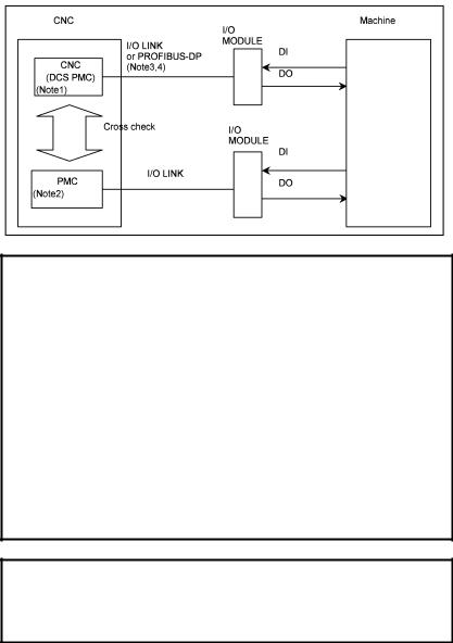
In order to setup double monitoring system, machine tool builder must connect safety signals to both I/O Link #1, #2 and I/O Link#3, #4, Profibus-DP.
IMPORTANT
If the safety input signals, except for Emergency Stop input signals, are connected to the I/O module, a Ladder program must be created to establish a one-to-one relationship between the actual input (X) and the input to the CNC (G).
The duplicated input/output signals are always checked for a mismatch, regardless of whether the safety function is active or not. When a signal state changes, the pair of signals may not match for some period because of a difference in response. The dual check safety function checks whether a mismatch between the two signals continues for a certain period of time, so that an error resulting from the difference in response can be avoided. The check period must be specified as a safety parameter.
Parameter number |
Name |
1945 |
Safe-related input/output signal check timer |
The following signals are not defined as safe-related I/O signals and are not duplicated. The signals, however, are necessary for the system.
-Input signal for making a protective door open request
-Input signal for starting the test mode
-Output signal for requesting a MCC off Test
-20 -
B-64004EN/02 |
3.SAFETY FUNCTIONS |
This section briefly describes the signals. For details, see Chapter 5, “OPERATION.” For specific connections, see the sample system configuration in Chapter 10.
NOTE
1Dual Check Safety PMC (DCS PMC)
2First path PMC, Second path PMC, Third path
PMC
Please refer to “FANUC Series 30i/300i/300is-MODEL A PMC PROGRAMMING MANUAL (B-63983EN)”
3When I/O Link and PROFIBUS-DP are connected to DCS PMC at the same time, the X/Y signals cannot be allocated to PROFIBUS-DP.
4Please activate “Broken wire detection” of the slave, which connect with PROFIBUS network as Safety-related I/O. As for detail, please refer to
“6.6. PROFIBUS-DP parameter settings”.
 CAUTION
Ladder functional instruction MOVB, MOVD and
MOVW cannot be used with ladder for Dual Check
Safety PMC. Use MOVN instead of them.
- 21 -
3.SAFETY FUNCTIONS |
|
|
B-64004EN/02 |
|||||
|
|
|
I/O related with Dual Check Safety Function |
|
|
|||
|
|
|
PMC(n=path(0-9)) |
DCS PMC (m=path(0-9) x20) |
|
|
||
|
|
Symbol |
Signal name |
|
I/O address |
|
|
|
|
1 |
*ESP |
Emergency Stop signal |
|
<X008#4,0,1> (PMC) |
|
Dual input |
|
|
|
|
|
|
<X008#4,0,1>(DCS PMC) |
|
monitoring |
|
|
2 |
*SGOPN |
Guard State signal |
|
Machine side signal |
|
Dual input |
|
|
|
*VLDVx |
Safety Check Request signal |
|
<Gn750#0-#7> (PMC) |
|
Dual input |
|
|
3 |
|
(Servo) |
|
<G(002+m)#0-#7>(DCS PMC) |
|
monitoring |
|
|
*VLDPs |
Safety Check Request signal |
|
<Gn751#0-#3>(PMC) |
|
Dual input |
|
|
|
|
|
|
|
||||
|
|
|
(Spindle) |
|
<G(003+m)#0-#3>(DCS PMC ) |
|
monitoring |
|
|
|
SVAn/ |
Safety Speed / Safety Position |
|
<Gn752/Gn753>(PMC) |
|
Dual input |
|
|
4 |
SVBn |
Selection signal (Servo) |
|
<G(004+m)/G(005+m)>(DCS PMC) |
|
monitoring |
|
|
SPAn/ |
Safety Speed Selection signal |
|
<Gn754>(PMC) |
|
Dual input |
|
|
|
|
|
|
|
||||
|
|
SPBn |
(Spindle) |
|
<G(006+m)>(DCS PMC) |
|
monitoring |
|
|
5 |
*SMC |
MCC Contact State signal |
|
<Gn748#6>(PMC) |
|
Dual input |
|
|
|
|
|
|
<G(000+m)#6>(DCS PMC) |
|
monitoring |
|
|
|
*DCALM |
MCC Off signal |
|
<F0748#7>(PMC) |
|
Dual output |
|
|
|
|
(for all system) |
|
<F000#7>(DCS PMC) |
|
|
|
|
|
*MCF |
MCC Off signal |
|
<Fn748#1>(PMC) |
|
Dual output |
|
|
6 |
|
(for each machine group) |
|
<F(000+m)#1>(DCS PMC) |
|
|
|
|
*MCFVx |
MCC Off signal |
|
<Fn752#0-#7>(PMC) |
|
Dual output |
|
|
|
|
|
|
|
||||
|
|
|
(for each servo axis) |
|
<F(004+m)#0-#7>(DCS PMC) |
|
|
|
|
|
*MCFPs |
MCC Off signal |
|
<Fn753#0-#3>(PMC) |
|
Dual output |
|
|
|
|
(for each spindle) |
|
<F(005+m)#0-#3>(DCS PMC) |
|
|
|
|
7 |
BRKx |
Safety Brake signal |
|
<Fn754#0-#7>(PMC) |
|
Dual output |
|
|
|
|
|
|
<F(006+m)#0-#7>(DCS PMC) |
|
|
|
|
8 |
SPS |
Safety Position Switch signal |
|
<Fn755-Fn758>(PMC) |
|
Dual output |
|
|
|
|
|
|
<F(007+m)-F(010+m)>(DCS PMC) |
|
|
|
|
|
|
Programmable Safety I/O |
|
|
|
Dual input |
|
|
9 |
|
signals |
|
|
|
monitoring |
|
|
|
|
|
|
|
|
Dual output |
|
|
10 |
ORQ |
Guard Open Request signal |
|
<Gn191#3>(PMC) |
|
Input |
|
|
11 |
OPT |
Test Mode signal |
|
<Fn191#2>(PMC) |
|
Input |
|
|
12 |
*OPIHB |
Guard Open Inhibit signal |
|
<Fn191#0>(PMC) |
|
Dual output |
|
|
|
|
|
|
<F(019+m)#0>(DCS PMC) |
|
|
|
|
|
RSVx |
Monitoring result signal (Servo) |
|
<Fn750#0-#7>(PMC) |
|
Dual output |
|
|
13 |
|
|
|
<F(002+m)#0-#7>(DCS PMC) |
|
|
|
|
RSPs |
Monitoring result signal |
|
<Fn751#0-#3>(PMC) |
|
Dual output |
|
|
|
|
|
|
|
||||
|
|
|
(Spindle) |
|
<F(003+m)#0-#3>(DCS PMC) |
|
|
|
|
14 |
RQT |
MCC Off Test Execution |
|
<Fn191#2>(PMC) |
|
Output |
|
|
|
|
Request signal |
|
|
|
|
|
|
15 |
POSEx |
Position Information Effect |
|
<Fn766#0-#7>(PMC) |
|
Dual output |
|
|
|
|
signal |
|
<F(018+m)#0-#7>(DCS PMC) |
|
|
|
Safe-related I/O
1. *ESP Emergency Stop signal (input)
This signal is Emergency Stop signal and is monitored in redundant mode.
The signal is connected to the *ESP input of the servo amplifier as well.
- 22 -
 Loading...