


 Loading...
FANUC Series 16/160/18/180 –TB
for Lathe
OPERATOR’S MANUAL
B-62444E/03

•No part of this manual may be reproduced in any form.
•All specifications and designs are subject to change without notice.
The export of this product is subject to the authorization of the government of the country from where the product is exported.
In this manual we have tried as much as possible to describe all the various matters. However, we cannot describe all the matters which must not be done, or which cannot be done, because there are so many possibilities.
Therefore, matters which are not especially described as possible in this manual should be regarded as ”impossible”.
This manual contains the program names or device names of other companies, some of which are registered trademarks of respective owners. However, these names are not followed by or in the main body.

B±62444E/03 |
Table of Contents |
|||
I. GENERAL |
|
|
||
1. |
GENERAL . . . . . . . . . . . . . . . . . . . . . . . . . . . . . . . . . . . . . . . . . . . . . . . . . . . . . . . . . . . . . . . . . |
3 |
||
|
1.1 |
GENERAL FLOW OF OPERATION OF CNC MACHINE TOOL . . . . . . . . . . . . . . . . . . . . . . . . . . . |
. 5 |
|
|
1.2 |
NOTES ON READING THIS MANUAL . . . . . . . . . . . . . . . . . . . . . . . . . . . . . . . . . . . . . . . . . . . . . . |
. 7 |
|
II. PROGRAMMING |
|
|
||
1. |
GENERAL . . . . . . . . . . . . . . . . . . . . . . . . . . . . . . . . . . . . . . . . . . . . . . . . . . . . . . . . . . . . . . . . |
11 |
||
|
1.1 |
TOOL MOVEMENT ALONG WORKPIECE PARTS FIGURE± INTERPOLATION . . . . . . . . . . . . |
12 |
|
|
1.2 |
FEED± FEED FUNCTION . . . . . . . . . . . . . . . . . . . . . . . . . . . . . . . . . . . . . . . . . . . . . . . . . . . . . . . . . . |
15 |
|
|
1.3 |
PART DRAWING AND TOOL MOVEMENT . . . . . . . . . . . . . . . . . . . . . . . . . . . . . . . . . . . . . . . . . . . |
16 |
|
|
|
1.3.1 Reference Position (Machine±Specific Position) . . . . . . . . . . . . . . . . . . . . . . . . . . . . . . . . . . . . . . . . . . . . . |
16 |
|
1.3.2Coordinate System on Part Drawing and Coordinate System Specified by CNC ± Coordinate System . . . 17
1.3.3 How to Indicate Command Dimensions for Moving the Tool ± Absolute, Incremental Commands . . . . . . 20
1.4 CUTTING SPEED ± SPINDLE SPEED FUNCTION . . . . . . . . . . . . . . . . . . . . . . . . . . . . . . . . . . . . . 23 1.5 SELECTION OF TOOL USED FOR VARIOUS MACHINING ± TOOL FUNCTION . . . . . . . . . . . 24 1.6 COMMAND FOR MACHINE OPERATIONS ± MISCELLANEOUS FUNCTION . . . . . . . . . . . . . 25 1.7 PROGRAM CONFIGURATION . . . . . . . . . . . . . . . . . . . . . . . . . . . . . . . . . . . . . . . . . . . . . . . . . . . . . 26 1.8 TOOL FIGURE AND TOOL MOTION BY PROGRAM . . . . . . . . . . . . . . . . . . . . . . . . . . . . . . . . . . 29 1.9 TOOL MOVEMENT RANGE ± STROKE . . . . . . . . . . . . . . . . . . . . . . . . . . . . . . . . . . . . . . . . . . . . . . 30
2. CONTROLLED AXES . . . . . . . . . . . . . . . . . . . . . . . . . . . . . . . . . . . . . . . . . . . . . . . . . . . . . . |
31 |
2.1 CONTROLLED AXES . . . . . . . . . . . . . . . . . . . . . . . . . . . . . . . . . . . . . . . . . . . . . . . . . . . . . . . . . . . . . 32 2.2 NAMES OF AXES . . . . . . . . . . . . . . . . . . . . . . . . . . . . . . . . . . . . . . . . . . . . . . . . . . . . . . . . . . . . . . . . 33 2.3 INCREMENT SYSTEM . . . . . . . . . . . . . . . . . . . . . . . . . . . . . . . . . . . . . . . . . . . . . . . . . . . . . . . . . . . . 34 2.4 MAXIMUM STROKES . . . . . . . . . . . . . . . . . . . . . . . . . . . . . . . . . . . . . . . . . . . . . . . . . . . . . . . . . . . . 35
3. PREPARATORY FUNCTION (G FUNCTION ) . . . . . . . . . . . . . . . . . . . . . . . . . . . . . . . . . 36 4. INTERPOLATION FUNCTIONS . . . . . . . . . . . . . . . . . . . . . . . . . . . . . . . . . . . . . . . . . . . . . . 41
4.1 POSITIONING (G00) . . . . . . . . . . . . . . . . . . . . . . . . . . . . . . . . . . . . . . . . . . . . . . . . . . . . . . . . . . . . . . 42 4.2 LINEAR INTERPOLATION (G01) . . . . . . . . . . . . . . . . . . . . . . . . . . . . . . . . . . . . . . . . . . . . . . . . . . . 44 4.3 CIRCULAR INTERPOLATION (G02,G03) . . . . . . . . . . . . . . . . . . . . . . . . . . . . . . . . . . . . . . . . . . . . . 45 4.4 HELICAL INTERPOLATION (G02,G03) . . . . . . . . . . . . . . . . . . . . . . . . . . . . . . . . . . . . . . . . . . . . . . 49 4.5 POLAR COORDINATE INTERPOLATION (G12.1,G13.1) . . . . . . . . . . . . . . . . . . . . . . . . . . . . . . . . 50 4.6 CYLINDRICAL INTERPOLATION (G07.1) . . . . . . . . . . . . . . . . . . . . . . . . . . . . . . . . . . . . . . . . . . . . 54 4.7 CONSTANT LEAD THREADING (G32) . . . . . . . . . . . . . . . . . . . . . . . . . . . . . . . . . . . . . . . . . . . . . . 57 4.8 VARIABLE±LEAD THREAD CUTTING (G34) . . . . . . . . . . . . . . . . . . . . . . . . . . . . . . . . . . . . . . . . . 61 4.9 CONTINUOUS THREAD CUTTING . . . . . . . . . . . . . . . . . . . . . . . . . . . . . . . . . . . . . . . . . . . . . . . . . 62 4.10 MULTIPLE±THREAD CUTTING . . . . . . . . . . . . . . . . . . . . . . . . . . . . . . . . . . . . . . . . . . . . . . . . . . . . 63 4.11 SKIP FUNCTION (G31) . . . . . . . . . . . . . . . . . . . . . . . . . . . . . . . . . . . . . . . . . . . . . . . . . . . . . . . . . . . . 65 4.12 MULTISTAGE SKIP . . . . . . . . . . . . . . . . . . . . . . . . . . . . . . . . . . . . . . . . . . . . . . . . . . . . . . . . . . . . . . . 67 4.13 TORQUE LIMIT SKIP (G31 P99) . . . . . . . . . . . . . . . . . . . . . . . . . . . . . . . . . . . . . . . . . . . . . . . . . . . . 68
5. FEED FUNCTIONS . . . . . . . . . . . . . . . . . . . . . . . . . . . . . . . . . . . . . . . . . . . . . . . . . . . . . . . . |
70 |
5.1 GENERAL . . . . . . . . . . . . . . . . . . . . . . . . . . . . . . . . . . . . . . . . . . . . . . . . . . . . . . . . . . . . . . . . . . . . . . . 71

|
TABLE OF CONTENTS |
B±62444EN/03 |
5.2 |
RAPID TRAVERSE . . . . . . . . . . . . . . . . . . . . . . . . . . . . . . . . . . . . . . . . . . . . . . . . . . . . . . |
. . . . . . . . . 73 |
5.3 |
CUTTING FEED . . . . . . . . . . . . . . . . . . . . . . . . . . . . . . . . . . . . . . . . . . . . . . . . . . . . . . . . . . |
. . . . . . . . 74 |
5.4 |
DWELL (G04) . . . . . . . . . . . . . . . . . . . . . . . . . . . . . . . . . . . . . . . . . . . . . . . . . . . . . . . . . . . . |
. . . . . . . . 77 |
6. REFERENCE POSITION . . . . . . . . . . . . . . . . . . . . . . . . . . . . . . . . . . . . . . . . . . . . . . . . . . . 78
7. FLOATING REFERENCE POSITION RETURN (G30.1) . . . . . . . . . . . . . . . . . . . . . . . . . 81
8. COORDINATE SYSTEM . . . . . . . . . . . . . . . . . . . . . . . . . . . . . . . . . . . . . . . . . . . . . . . . . . . . 82
8.1 MACHINE COORDINATE SYSTEM . . . . . . . . . . . . . . . . . . . . . . . . . . . . . . . . . . . . . . . . . . . . . . . . . 83 8.2 WORKPIECE COORDINATE SYSTEM . . . . . . . . . . . . . . . . . . . . . . . . . . . . . . . . . . . . . . . . . . . . . . . 84
8.2.1 Setting a Workpiece Coordinate System . . . . . . . . . . . . . . . . . . . . . . . . . . . . . . . . . . . . . . . . . . . . . . . . . . . . 84 8.2.2 Selecting a Workpiece Coordinate System . . . . . . . . . . . . . . . . . . . . . . . . . . . . . . . . . . . . . . . . . . . . . . . . . . 85 8.2.3 Changing Workpiece Coordinate System . . . . . . . . . . . . . . . . . . . . . . . . . . . . . . . . . . . . . . . . . . . . . . . . . . . 87 8.2.4 Workpiece Coordinate System Preset (G92.1) . . . . . . . . . . . . . . . . . . . . . . . . . . . . . . . . . . . . . . . . . . . . . . . 89 8.2.5 Workpiece Coordinate System shift . . . . . . . . . . . . . . . . . . . . . . . . . . . . . . . . . . . . . . . . . . . . . . . . . . . . . . . 91
8.3 LOCAL COORDINATE SYSTEM . . . . . . . . . . . . . . . . . . . . . . . . . . . . . . . . . . . . . . . . . . . . . . . . . . . . 92 8.4 PLANE SELECTION . . . . . . . . . . . . . . . . . . . . . . . . . . . . . . . . . . . . . . . . . . . . . . . . . . . . . . . . . . . . . . 94
9. COORDINATE VALUE AND DIMENSION . . . . . . . . . . . . . . . . . . . . . . . . . . . . . . . . . . . . . 95
9.1 ABSOLUTE AND INCREMENTAL PROGRAMMING (G90, G91) . . . . . . . . . . . . . . . . . . . . . . . . . 96 9.2 INCH/METRIC CONVERSION(G20,G21) . . . . . . . . . . . . . . . . . . . . . . . . . . . . . . . . . . . . . . . . . . . . . 97 9.3 DECIMAL POINT PROGRAMMING . . . . . . . . . . . . . . . . . . . . . . . . . . . . . . . . . . . . . . . . . . . . . . . . . 98 9.4 DIAMETER AND RADIUS PROGRAMMING . . . . . . . . . . . . . . . . . . . . . . . . . . . . . . . . . . . . . . . . . 99
10. SPINDLE SPEED FUNCTION . . . . . . . . . . . . . . . . . . . . . . . . . . . . . . . . . . . . . . . . . . . . . . |
100 |
10.1 SPECIFYING THE SPINDLE SPEED WITH A BINARY CODE . . . . . . . . . . . . . . . . . . . . . . . . . . 101 10.2 SPECIFYING THE SPINDLE SPEED VALUE DIRECTLY (S5±DIGIT COMMAND) . . . . . . . . . 101 10.3 CONSTANT SURFACE SPEED CONTROL (G96, G97) . . . . . . . . . . . . . . . . . . . . . . . . . . . . . . . . . 101 10.4 SPINDLE SPEED FLUCTUATION DETECTION FUNCTION (G25, G26) . . . . . . . . . . . . . . . . . . 105 10.5 SPINDLE POSITIONING FUNCTION . . . . . . . . . . . . . . . . . . . . . . . . . . . . . . . . . . . . . . . . . . . . . . . 108
10.5.1 Spindle Orientation . . . . . . . . . . . . . . . . . . . . . . . . . . . . . . . . . . . . . . . . . . . . . . . . . . . . . . . . . . . . . . . . . . . 108 10.5.2 Spindle Positioning . . . . . . . . . . . . . . . . . . . . . . . . . . . . . . . . . . . . . . . . . . . . . . . . . . . . . . . . . . . . . . . . . . . 108 10.5.3 Canceling Spindle Positioning . . . . . . . . . . . . . . . . . . . . . . . . . . . . . . . . . . . . . . . . . . . . . . . . . . . . . . . . . . 110
11. TOOL FUNCTION (T FUNCTION) . . . . . . . . . . . . . . . . . . . . . . . . . . . . . . . . . . . . . . . . . . |
111 |
|
11.1 |
TOOL SELECTION . . . . . . . . . . . . . . . . . . . . . . . . . . . . . . . . . . . . . . . . . . . . . . . . . . . . . . . . . . . . . . |
112 |
11.2 |
TOOL LIFE MANAGEMENT . . . . . . . . . . . . . . . . . . . . . . . . . . . . . . . . . . . . . . . . . . . . . . . . . . . . . . |
113 |
11.2.1 Program of Tool Life Data . . . . . . . . . . . . . . . . . . . . . . . . . . . . . . . . . . . . . . . . . . . . . . . . . . . . . . . . . . . . |
. 113 |
|
11.2.2 COUNTING A TOOL LIFE . . . . . . . . . . . . . . . . . . . . . . . . . . . . . . . . . . . . . . . . . . . . . . . . . . . . . . . . . . . . |
115 |
|
11.2.3 Specifying a Tool Group in a Machining Program . . . . . . . . . . . . . . . . . . . . . . . . . . . . . . . . . . . . . . . . . . . |
116 |
|
12. AUXILIARY FUNCTION . . . . . . . . . . . . . . . . . . . . . . . . . . . . . . . . . . . . . . . . . . . . . . . . . . . |
117 |
|
12.1 AUXILIARY FUNCTION (M FUNCTION) . . . . . . . . . . . . . . . . . . . . . . . . . . . . . . . . . . . . . . . . . . . 118 12.2 MULTIPLE M COMMANDS IN A SINGLE BLOCK . . . . . . . . . . . . . . . . . . . . . . . . . . . . . . . . . . . 119 12.3 M CODE GROUP CHECK FUNCTION . . . . . . . . . . . . . . . . . . . . . . . . . . . . . . . . . . . . . . . . . . . . . . 120 12.4 THE SECOND AUXILIARY FUNCTIONS (B CODES) . . . . . . . . . . . . . . . . . . . . . . . . . . . . . . . . . 121

B±62444E/03 |
TABLE OF CONTENTS |
|
13. PROGRAM CONFIGURATION . . . . . . . . . . . . . . . . . . . . . . . . . . . . . . . . . . . . . . . . . . . . . |
122 |
|
13.1 |
PROGRAM COMPONENTS OTHER THAN PROGRAM SECTIONS . . . . . . . . . . . . . . . . . . . . . |
124 |
13.2 |
PROGRAM SECTION CONFIGURATION . . . . . . . . . . . . . . . . . . . . . . . . . . . . . . . . . . . . . . . . . . . . |
127 |
13.3 |
SUBPROGRAM . . . . . . . . . . . . . . . . . . . . . . . . . . . . . . . . . . . . . . . . . . . . . . . . . . . . . . . . . . . . . . . . . |
133 |
14. FUNCTIONS TO SIMPLIFY PROGRAMMING . . . . . . . . . . . . . . . . . . . . . . . . . . . . . . . . |
136 |
|
14.1 |
CANNED CYCLE (G90, G92, G94) . . . . . . . . . . . . . . . . . . . . . . . . . . . . . . . . . . . . . . . . . . . . . . . . . . |
137 |
14.1.1 Outer Diameter / Internal Diameter Cutting Cycle (G90) . . . . . . . . . . . . . . . . . . . . . . . . . . . . . . . . . . . . . |
. 137 |
|
14.1.2 Thread Cutting Cycle (G92) . . . . . . . . . . . . . . . . . . . . . . . . . . . . . . . . . . . . . . . . . . . . . . . . . . . . . . . . . . . |
. 139 |
|
14.1.3 End Face Turning Cycle (G94) . . . . . . . . . . . . . . . . . . . . . . . . . . . . . . . . . . . . . . . . . . . . . . . . . . . . . . . . . . |
142 |
|
14.1.4 How to Use Canned Cycles (G90, G92, G94) . . . . . . . . . . . . . . . . . . . . . . . . . . . . . . . . . . . . . . . . . . . . . . |
145 |
|
14.2 MULTIPLE REPETITIVE CYCLE (G70±G76) . . . . . . . . . . . . . . . . . . . . . . . . . . . . . . . . . . . . . . . . . 147
14.2.1 Stock Removal in Turning (G71) . . . . . . . . . . . . . . . . . . . . . . . . . . . . . . . . . . . . . . . . . . . . . . . . . . . . . . . . 147 14.2.2 Stock Removal in Facing (G72) . . . . . . . . . . . . . . . . . . . . . . . . . . . . . . . . . . . . . . . . . . . . . . . . . . . . . . . . . 151 14.2.3 Pattern Repeating (G73) . . . . . . . . . . . . . . . . . . . . . . . . . . . . . . . . . . . . . . . . . . . . . . . . . . . . . . . . . . . . . . . 152 14.2.4 Finishing Cycle (G70) . . . . . . . . . . . . . . . . . . . . . . . . . . . . . . . . . . . . . . . . . . . . . . . . . . . . . . . . . . . . . . . . . 153 14.2.5 End Face Peck Drilling Cycle (G74) . . . . . . . . . . . . . . . . . . . . . . . . . . . . . . . . . . . . . . . . . . . . . . . . . . . . . . 157 14.2.6 Outer Diameter / Internal Diameter Drilling Cycle (G75) . . . . . . . . . . . . . . . . . . . . . . . . . . . . . . . . . . . . . 158 14.2.7 Multiple Thread Cutting Cycle (G76) . . . . . . . . . . . . . . . . . . . . . . . . . . . . . . . . . . . . . . . . . . . . . . . . . . . . . 159 14.2.8 Notes on Multiple Repetitive Cycle (G70±G76) . . . . . . . . . . . . . . . . . . . . . . . . . . . . . . . . . . . . . . . . . . . . . 163
14.3 |
CANNED CYCLE FOR DRILLING (G80±G89) . . . . . . . . . . . . . . . . . . . . . . . . . . . . . . . . . . . . . . . . |
164 |
14.3.1 Front Drilling Cycle (G83) / Side Drilling Cycle (G87) . . . . . . . . . . . . . . . . . . . . . . . . . . . . . . . . . . . . . . . |
167 |
|
14.3.2 Front Tapping Cycle (G84) / Side Tapping Cycle (G88) . . . . . . . . . . . . . . . . . . . . . . . . . . . . . . . . . . . . . . |
170 |
|
14.3.3 Front Boring Cycle (G85) / Side Boring Cycle (G89) . . . . . . . . . . . . . . . . . . . . . . . . . . . . . . . . . . . . . . . . |
172 |
|
14.3.4 Canned Cycle for Drilling Cancel (G80) . . . . . . . . . . . . . . . . . . . . . . . . . . . . . . . . . . . . . . . . . . . . . . . . . . |
173 |
|
14.3.5 Precautions to Be Taken by Operator . . . . . . . . . . . . . . . . . . . . . . . . . . . . . . . . . . . . . . . . . . . . . . . . . . . . . |
174 |
|
14.4 |
CANNED GRINDING CYCLE (FOR GRINDING MACHINE) . . . . . . . . . . . . . . . . . . . . . . . . . . . |
175 |
14.4.1 Traverse Grinding Cycle (G71) . . . . . . . . . . . . . . . . . . . . . . . . . . . . . . . . . . . . . . . . . . . . . . . . . . . . . . . . . . 175 14.4.2 Traverse Direct Fixed±dimension Grinding Cycle (G72) . . . . . . . . . . . . . . . . . . . . . . . . . . . . . . . . . . . . . . 176 14.4.3 Oscillation Grinding Cycle (G73) . . . . . . . . . . . . . . . . . . . . . . . . . . . . . . . . . . . . . . . . . . . . . . . . . . . . . . . . 177 14.4.4 Oscillation Direct Fixed±Dimension Grinding Cycle . . . . . . . . . . . . . . . . . . . . . . . . . . . . . . . . . . . . . . . . . 178
14.5 CHAMFERING AND CORNER R . . . . . . . . . . . . . . . . . . . . . . . . . . . . . . . . . . . . . . . . . . . . . . . . . . . 179 14.6 MIRROR IMAGE FOR DOUBLE TURRET (G68, G69) . . . . . . . . . . . . . . . . . . . . . . . . . . . . . . . . . 182 14.7 DIRECT DRAWING DIMENSIONS PROGRAMMING . . . . . . . . . . . . . . . . . . . . . . . . . . . . . . . . . 183 14.8 RIGID TAPPING . . . . . . . . . . . . . . . . . . . . . . . . . . . . . . . . . . . . . . . . . . . . . . . . . . . . . . . . . . . . . . . . . 188
14.8.1 Front Face Rigid Tapping Cycle (G84)/Side Face Rigid Tapping Cycle (G88) . . . . . . . . . . . . . . . . . . . . . 189
15. COMPENSATION FUNCTION . . . . . . . . . . . . . . . . . . . . . . . . . . . . . . . . . . . . . . . . . . . . . . |
192 |
15.1 TOOL OFFSET . . . . . . . . . . . . . . . . . . . . . . . . . . . . . . . . . . . . . . . . . . . . . . . . . . . . . . . . . . . . . . . . . . |
193 |
15.1.1 Tool Geometry Offset And Tool Wear Offset . . . . . . . . . . . . . . . . . . . . . . . . . . . . . . . . . . . . . . . . . . . . . . . 193 15.1.2 T code for Tool Offset . . . . . . . . . . . . . . . . . . . . . . . . . . . . . . . . . . . . . . . . . . . . . . . . . . . . . . . . . . . . . . . . . 194 15.1.3 Tool Selection . . . . . . . . . . . . . . . . . . . . . . . . . . . . . . . . . . . . . . . . . . . . . . . . . . . . . . . . . . . . . . . . . . . . . . . 194 15.1.4 Offset Number . . . . . . . . . . . . . . . . . . . . . . . . . . . . . . . . . . . . . . . . . . . . . . . . . . . . . . . . . . . . . . . . . . . . . . . 194 15.1.5 Offset . . . . . . . . . . . . . . . . . . . . . . . . . . . . . . . . . . . . . . . . . . . . . . . . . . . . . . . . . . . . . . . . . . . . . . . . . . . . . . 195 15.1.6 G53, G28, G30, and G30.1 Commands When Tool Position Offset is Applied . . . . . . . . . . . . . . . . . . . . . 198
15.2 OVERVIEW OF TOOL NOSE RADIUS COMPENSATION . . . . . . . . . . . . . . . . . . . . . . . . . . . . . . 202
15.2.1 Imaginary Tool Nose . . . . . . . . . . . . . . . . . . . . . . . . . . . . . . . . . . . . . . . . . . . . . . . . . . . . . . . . . . . . . . . . . . 202 15.2.2 Direction of Imaginary Tool Nose . . . . . . . . . . . . . . . . . . . . . . . . . . . . . . . . . . . . . . . . . . . . . . . . . . . . . . . . 204

TABLE OF CONTENTS |
B±62444EN/03 |
|
|
15.2.3 Offset Number And Offset Value . . . . . . . . . . . . . . . . . . . . . . . . . . . . . . . . . . . . . . . . . . . . . . . . . . . . . . . . 205 15.2.4 Work Position and Move Command . . . . . . . . . . . . . . . . . . . . . . . . . . . . . . . . . . . . . . . . . . . . . . . . . . . . . . 207 15.2.5 Notes on tool Nose Radius Compensation . . . . . . . . . . . . . . . . . . . . . . . . . . . . . . . . . . . . . . . . . . . . . . . . . 212
15.3 DETAILS OF TOOL NOSE RADIUS COMPENSATION . . . . . . . . . . . . . . . . . . . . . . . . . . . . . . . . 215
15.3.1 General . . . . . . . . . . . . . . . . . . . . . . . . . . . . . . . . . . . . . . . . . . . . . . . . . . . . . . . . . . . . . . . . . . . . . . . . . . . . 215 15.3.2 Tool Movement in Start±up . . . . . . . . . . . . . . . . . . . . . . . . . . . . . . . . . . . . . . . . . . . . . . . . . . . . . . . . . . . . . 217 15.3.3 Tool Movement in Offset Mode . . . . . . . . . . . . . . . . . . . . . . . . . . . . . . . . . . . . . . . . . . . . . . . . . . . . . . . . . 219 15.3.4 Tool Movement in Offset Mode Cancel . . . . . . . . . . . . . . . . . . . . . . . . . . . . . . . . . . . . . . . . . . . . . . . . . . . 232 15.3.5 Interference Check . . . . . . . . . . . . . . . . . . . . . . . . . . . . . . . . . . . . . . . . . . . . . . . . . . . . . . . . . . . . . . . . . . . 235 15.3.6 Overcutting by Tool Nose Radius Compensation . . . . . . . . . . . . . . . . . . . . . . . . . . . . . . . . . . . . . . . . . . . . 240 15.3.7 Correction in Chamfering and Corner Arcs . . . . . . . . . . . . . . . . . . . . . . . . . . . . . . . . . . . . . . . . . . . . . . . . 241 15.3.8 Input Command from MDI . . . . . . . . . . . . . . . . . . . . . . . . . . . . . . . . . . . . . . . . . . . . . . . . . . . . . . . . . . . . . 243 15.3.9 General Precautions for Offset Operations . . . . . . . . . . . . . . . . . . . . . . . . . . . . . . . . . . . . . . . . . . . . . . . . . 244 15.3.10 G53, G28, G30, and G30.1 Commands in Tool±tip Radius Compensation Mode . . . . . . . . . . . . . . . . . . . 245
15.4 CORNER CIRCULAR INTERPOLATION FUNCTION (G39) . . . . . . . . . . . . . . . . . . . . . . . . . . . . 254
15.5TOOL COMPENSA± TION VALUES, NUMBER OF COMPENSATION VALUES,
AND ENTERING VALUES FROM THE PROGRAM (G10) . . . . . . . . . . . . . . . . . . . . . . . . . . . . . . 256
15.5.1 Tool Compensation and Number of Tool Compensation . . . . . . . . . . . . . . . . . . . . . . . . . . . . . . . . . . . . . . 256 15.5.2 Changing of Tool Offset value (Programmable Data Input ) (G10) . . . . . . . . . . . . . . . . . . . . . . . . . . . . . . 257
15.6 |
AUTOMATIC TOOL OFFSET (G36, G37) . . . . . . . . . . . . . . . . . . . . . . . . . . . . . . . . . . . . . . . . . . . . |
258 |
15.7 |
COORDINATE ROTATION (G68.1, G69.1) . . . . . . . . . . . . . . . . . . . . . . . . . . . . . . . . . . . . . . . . . . . |
261 |
16. CUSTOM MACRO . . . . . . . . . . . . . . . . . . . . . . . . . . . . . . . . . . . . . . . . . . . . . . . . . . . . . . . . |
265 |
|
16.1 VARIABLES . . . . . . . . . . . . . . . . . . . . . . . . . . . . . . . . . . . . . . . . . . . . . . . . . . . . . . . . . . . . . . . . . . . . 266 16.2 SYSTEM VARIABLES . . . . . . . . . . . . . . . . . . . . . . . . . . . . . . . . . . . . . . . . . . . . . . . . . . . . . . . . . . . . 270 16.3 ARITHMETIC AND LOGIC OPERATION . . . . . . . . . . . . . . . . . . . . . . . . . . . . . . . . . . . . . . . . . . . . 276 16.4 MACRO STATEMENTS AND NC STATEMENTS . . . . . . . . . . . . . . . . . . . . . . . . . . . . . . . . . . . . . 280 16.5 BRANCH AND REPETITION . . . . . . . . . . . . . . . . . . . . . . . . . . . . . . . . . . . . . . . . . . . . . . . . . . . . . . 281
16.5.1 Unconditional Branch (GOTO Statement) . . . . . . . . . . . . . . . . . . . . . . . . . . . . . . . . . . . . . . . . . . . . . . . . . 281 16.5.2 Conditional Branch (IF Statement) . . . . . . . . . . . . . . . . . . . . . . . . . . . . . . . . . . . . . . . . . . . . . . . . . . . . . . . 281 16.5.3 Repetition (While Statement) . . . . . . . . . . . . . . . . . . . . . . . . . . . . . . . . . . . . . . . . . . . . . . . . . . . . . . . . . . . 282
16.6 |
MACRO CALL . . . . . . . . . . . . . . . . . . . . . . . . . . . . . . . . . . . . . . . . . . . . . . . . . . . . . . . . . . . . . . . . . . |
285 |
|
16.6.1 |
Simple Call (G65) . . . . . . . . . . . . . . . . . . . . . . . . . . . . . . . . . . . . . . . . . . . . . . . . . . . . . . . . . . . . . . . . . . . . |
285 |
|
16.6.2 |
Modal Call (G66) . . . . . . . . . . . . . . . . . . . . . . . . . . . . . . . . . . . . . . . . . . . . . . . . . . . . . . . . . . . . . . . . . . . . |
290 |
|
16.6.3 Macro Call Using G Code . . . . . . . . . . . . . . . . . . . . . . . . . . . . . . . . . . . . . . . . . . . . . . . . . . . . . . . . . . . . . . |
292 |
||
16.6.4 Macro Call Using an M Code . . . . . . . . . . . . . . . . . . . . . . . . . . . . . . . . . . . . . . . . . . . . . . . . . . . . . . . . . . . |
293 |
||
16.6.5 Subprogram Call Using an M Code . . . . . . . . . . . . . . . . . . . . . . . . . . . . . . . . . . . . . . . . . . . . . . . . . . . . . . |
294 |
||
16.6.6 Subprogram Calls Using a T Code . . . . . . . . . . . . . . . . . . . . . . . . . . . . . . . . . . . . . . . . . . . . . . . . . . . . . . . |
295 |
||
16.6.7 |
Sample Program . . . . . . . . . . . . . . . . . . . . . . . . . . . . . . . . . . . . . . . . . . . . . . . . . . . . . . . . . . . . . . . . . . . . . |
296 |
|
16.7 |
PROCESSING MACRO STATEMENTS . . . . . . . . . . . . . . . . . . . . . . . . . . . . . . . . . . . . . . . . . . . . . . |
298 |
|
16.8 |
REGISTERING CUSTOM MACRO PROGRAMS . . . . . . . . . . . . . . . . . . . . . . . . . . . . . . . . . . . . . . |
300 |
|
16.9 |
LIMITATIONS . . . . . . . . . . . . . . . . . . . . . . . . . . . . . . . . . . . . . . . . . . . . . . . . . . . . . . . . . . . . . . . . . . . |
301 |
|
16.10 |
EXTERNAL OUTPUT COMMANDS . . . . . . . . . . . . . . . . . . . . . . . . . . . . . . . . . . . . . . . . . . . . . . . . |
302 |
|
16.11 |
INTERRUPTION TYPE CUSTOM MACRO . . . . . . . . . . . . . . . . . . . . . . . . . . . . . . . . . . . . . . . . . . |
306 |
|
16.11.1 Specification Method . . . . . . . . . . . . . . . . . . . . . . . . . . . . . . . . . . . . . . . . . . . . . . . . . . . . . . . . . . . . . . . . . 307
16.11.2 Details of Functions . . . . . . . . . . . . . . . . . . . . . . . . . . . . . . . . . . . . . . . . . . . . . . . . . . . . . . . . . . . . . . . . . . . 308
17. PROGRAMMABLE PARAMETER ENTRY (G10) . . . . . . . . . . . . . . . . . . . . . . . . . . . . . |
315 |
18. MEMORY OPERATION by FS15 TAPE FORMAT . . . . . . . . . . . . . . . . . . . . . . . . . . . . . |
318 |
18.1 ADDRESSES AND SPECIFIABLE VALUE RANGE FOR SERIES 15 TAPE FORMAT . . . . . . . 319

B±62444E/03 |
TABLE OF CONTENTS |
|
|
18.2 EQUAL±LEAD THREADING . . . . . . . . . . . . . . . . . . . . . . . . . . . . . . . . . . . . . . . . . . . . . . . . . . . . . . 320 18.3 SUBPROGRAM CALLING . . . . . . . . . . . . . . . . . . . . . . . . . . . . . . . . . . . . . . . . . . . . . . . . . . . . . . . . 321 18.4 CANNED CYCLE . . . . . . . . . . . . . . . . . . . . . . . . . . . . . . . . . . . . . . . . . . . . . . . . . . . . . . . . . . . . . . . 322 18.5 MULTIPLE REPETITIVE CANNED TURNING CYCLE . . . . . . . . . . . . . . . . . . . . . . . . . . . . . . . . 323 18.6 CANNED DRILLING CYCLE FORMATS . . . . . . . . . . . . . . . . . . . . . . . . . . . . . . . . . . . . . . . . . . . . 325
19. FUNCTIONS FOR HIGH SPEED CUTTING . . . . . . . . . . . . . . . . . . . . . . . . . . . . . . . . . . 329
19.1 HIGH SPEED CYCLE CUTTING . . . . . . . . . . . . . . . . . . . . . . . . . . . . . . . . . . . . . . . . . . . . . . . . . . . 330
19.2DISTRIBUTION PROCESSING TERMINATION MONITORING FUNCTION
FOR THE HIGH±SPEED MACHINING COMMAND (G05) . . . . . . . . . . . . . . . . . . . . . . . . . . . . . . 332
20. AXIS CONTROL FUNCTION . . . . . . . . . . . . . . . . . . . . . . . . . . . . . . . . . . . . . . . . . . . . . . . |
333 |
20.1 POLIGONAL TURNING . . . . . . . . . . . . . . . . . . . . . . . . . . . . . . . . . . . . . . . . . . . . . . . . . . . . . . . . . . 334 20.2 ROTARY AXIS ROLL±OVER . . . . . . . . . . . . . . . . . . . . . . . . . . . . . . . . . . . . . . . . . . . . . . . . . . . . . . 340 20.3 SIMPLE SYNCHRONIZATION CONTROL . . . . . . . . . . . . . . . . . . . . . . . . . . . . . . . . . . . . . . . . . . . 341 20.4 HIGH±SPEED REMOTE BUFFER . . . . . . . . . . . . . . . . . . . . . . . . . . . . . . . . . . . . . . . . . . . . . . . . . . 343
20.4.1 High±speed Remote Buffer A (G05) . . . . . . . . . . . . . . . . . . . . . . . . . . . . . . . . . . . . . . . . . . . . . . . . . . . . . . 343
20.5 SYNCHRONIZATION CONTROL . . . . . . . . . . . . . . . . . . . . . . . . . . . . . . . . . . . . . . . . . . . . . . . . . . 346 20.6 B±AXIS CONTROL (G100, G101, G102, G103, G110) . . . . . . . . . . . . . . . . . . . . . . . . . . . . . . . . . . 347 20.7 ANGULAR AXIS CONTROL . . . . . . . . . . . . . . . . . . . . . . . . . . . . . . . . . . . . . . . . . . . . . . . . . . . . . . 357 20.8 TOOL WITHDRAWAL AND RETURN (G10.6) . . . . . . . . . . . . . . . . . . . . . . . . . . . . . . . . . . . . . . . . 359
21. TWO±PATH CONTROL FUNCTION . . . . . . . . . . . . . . . . . . . . . . . . . . . . . . . . . . . . . . . . . 362
21.1 GENERAL . . . . . . . . . . . . . . . . . . . . . . . . . . . . . . . . . . . . . . . . . . . . . . . . . . . . . . . . . . . . . . . . . . . . . . 363 21.2 WAITING FOR TOOL POSTS . . . . . . . . . . . . . . . . . . . . . . . . . . . . . . . . . . . . . . . . . . . . . . . . . . . . . . 365 21.3 TOOL POST INTERFACE CHECK . . . . . . . . . . . . . . . . . . . . . . . . . . . . . . . . . . . . . . . . . . . . . . . . . . 367
21.3.1 General . . . . . . . . . . . . . . . . . . . . . . . . . . . . . . . . . . . . . . . . . . . . . . . . . . . . . . . . . . . . . . . . . . . . . . . . . . . . 367 21.3.2 Data Setting for the Tool Post Interference Check Function . . . . . . . . . . . . . . . . . . . . . . . . . . . . . . . . . . . . 367 21.3.3 Setting and Display of Interference Forbidden Areas for Tool Post Interference Checking . . . . . . . . . . . . 371 21.3.4 Conditions for Making a Tool Post Interference Check . . . . . . . . . . . . . . . . . . . . . . . . . . . . . . . . . . . . . . . 372 21.3.5 Execution of Tool Post Interference Checking . . . . . . . . . . . . . . . . . . . . . . . . . . . . . . . . . . . . . . . . . . . . . . 373 21.3.6 Example of Making a Tool Post Interference Check . . . . . . . . . . . . . . . . . . . . . . . . . . . . . . . . . . . . . . . . . . 375
21.4 BALANCE CUT (G68,G69) . . . . . . . . . . . . . . . . . . . . . . . . . . . . . . . . . . . . . . . . . . . . . . . . . . . . . . . . 377 21.5 MEMORY COMMON TO TOOL POSTS . . . . . . . . . . . . . . . . . . . . . . . . . . . . . . . . . . . . . . . . . . . . . 379 21.6 SPINDLE CONTROL IN TWO±PATH CONTROL . . . . . . . . . . . . . . . . . . . . . . . . . . . . . . . . . . . . . 380 21.7 SYNCHRONIZATION CONTROL AND COMPOSITE CONTROL . . . . . . . . . . . . . . . . . . . . . . . . 382
22. PATTERN DATA INPUT FUNCTION . . . . . . . . . . . . . . . . . . . . . . . . . . . . . . . . . . . . . . . . . 385
22.1 DISPLAYING THE PATTERN MENU . . . . . . . . . . . . . . . . . . . . . . . . . . . . . . . . . . . . . . . . . . . . . . . 386 22.2 PATTERN DATA DISPLAY . . . . . . . . . . . . . . . . . . . . . . . . . . . . . . . . . . . . . . . . . . . . . . . . . . . . . . . . 390
22.3CHARACTERS AND CODES TO BE USED FOR THE PATTERN DATA INPUT FUNCTION . 394
III.OPERATION
1. GENERAL . . . . . . . . . . . . . . . . . . . . . . . . . . . . . . . . . . . . . . . . . . . . . . . . . . . . . . . . . . . . . . . |
399 |
1.1 MANUAL OPERATION . . . . . . . . . . . . . . . . . . . . . . . . . . . . . . . . . . . . . . . . . . . . . . . . . . . . . . . . . . . 400

|
|
TABLE OF CONTENTS |
B±62444EN/03 |
|
|
|
|
1.2 |
TOOL MOVEMENT BY PROGRAMING ± AUTOMATIC OPERATION . . . . . . . . . . . |
. . . . . . . . 402 |
|
1.3 |
AUTOMATIC OPERATION . . . . . . . . . . . . . . . . . . . . . . . . . . . . . . . . . . . . . . . . . . . . . . . . |
. . . . . . . . 403 |
|
1.4 |
TESTING A PROGRAM . . . . . . . . . . . . . . . . . . . . . . . . . . . . . . . . . . . . . . . . . . . . . . . . . . . |
. . . . . . . 405 |
|
|
1.4.1 |
Check by Running the Machine . . . . . . . . . . . . . . . . . . . . . . . . . . . . . . . . . . . . . . . . . . . . . . . . . |
. . . . . . . . 405 |
|
1.4.2 |
How to View the Position Display Change without Running the Machine . . . . . . . . . . . . . . . . |
. . . . . . . . 406 |
1.5 EDITING A PART PROGRAM . . . . . . . . . . . . . . . . . . . . . . . . . . . . . . . . . . . . . . . . . . . . . . . . . . . . . 407 1.6 DISPLAYING AND SETTING DATA . . . . . . . . . . . . . . . . . . . . . . . . . . . . . . . . . . . . . . . . . . . . . . . . 408 1.7 DISPLAY . . . . . . . . . . . . . . . . . . . . . . . . . . . . . . . . . . . . . . . . . . . . . . . . . . . . . . . . . . . . . . . . . . . . . . . 411
1.7.1 Program Display . . . . . . . . . . . . . . . . . . . . . . . . . . . . . . . . . . . . . . . . . . . . . . . . . . . . . . . . . . . . . . . . . . . . . 411 1.7.2 Current Position Display . . . . . . . . . . . . . . . . . . . . . . . . . . . . . . . . . . . . . . . . . . . . . . . . . . . . . . . . . . . . . . . 412 1.7.3 Alarm Display . . . . . . . . . . . . . . . . . . . . . . . . . . . . . . . . . . . . . . . . . . . . . . . . . . . . . . . . . . . . . . . . . . . . . . . 412 1.7.4 Parts Count Display, Run Time Display . . . . . . . . . . . . . . . . . . . . . . . . . . . . . . . . . . . . . . . . . . . . . . . . . . . 413 1.7.5 Graphic Display (See Section III±12) . . . . . . . . . . . . . . . . . . . . . . . . . . . . . . . . . . . . . . . . . . . . . . . . . . . . . 413
1.8 DATA OUTPUT . . . . . . . . . . . . . . . . . . . . . . . . . . . . . . . . . . . . . . . . . . . . . . . . . . . . . . . . . . . . . . . . . . 415
2. OPERATIONAL DEVICES . . . . . . . . . . . . . . . . . . . . . . . . . . . . . . . . . . . . . . . . . . . . . . . . . |
416 |
2.1 SETTING AND DISPLAY UNIT . . . . . . . . . . . . . . . . . . . . . . . . . . . . . . . . . . . . . . . . . . . . . . . . . . . . |
417 |
2.1.1 9-inch Monochrome/Color CRT/MDI Panel (Small Type) . . . . . . . . . . . . . . . . . . . . . . . . . . . . . . . . . . . . . 418 2.1.2 9-inch Monochrome/Color CRT/MDI Panel (Standard Type) . . . . . . . . . . . . . . . . . . . . . . . . . . . . . . . . . . 418 2.1.3 9-inch Monochrome PDP/MDI (Standard Type) . . . . . . . . . . . . . . . . . . . . . . . . . . . . . . . . . . . . . . . . . . . . 419 2.1.4 14-inch Color CRT/MDI (Horizontal Type) . . . . . . . . . . . . . . . . . . . . . . . . . . . . . . . . . . . . . . . . . . . . . . . . 419 2.1.5 14-inch Color CRT/MDI (Vertical Type) . . . . . . . . . . . . . . . . . . . . . . . . . . . . . . . . . . . . . . . . . . . . . . . . . . 420 2.1.6 9-inch Monochrome/Color CRT (Separate Type) . . . . . . . . . . . . . . . . . . . . . . . . . . . . . . . . . . . . . . . . . . . . 420 2.1.7 9±inch Monochrome PDP (Separate Type) . . . . . . . . . . . . . . . . . . . . . . . . . . . . . . . . . . . . . . . . . . . . . . . . . 421 2.1.8 7.2±inch Monochrome LCD (Separate Type) . . . . . . . . . . . . . . . . . . . . . . . . . . . . . . . . . . . . . . . . . . . . . . . 421 2.1.9 8.4±inch Color LCD (Separate Type) . . . . . . . . . . . . . . . . . . . . . . . . . . . . . . . . . . . . . . . . . . . . . . . . . . . . . 422 2.1.10 9.5-inch Color LCD/MDI (Horizontal Type) . . . . . . . . . . . . . . . . . . . . . . . . . . . . . . . . . . . . . . . . . . . . . . . 422 2.1.11 9.5-inch Color LCD/MDI (Vertical Type) . . . . . . . . . . . . . . . . . . . . . . . . . . . . . . . . . . . . . . . . . . . . . . . . . . 423 2.1.12 Separate Type MDI (Small Type) . . . . . . . . . . . . . . . . . . . . . . . . . . . . . . . . . . . . . . . . . . . . . . . . . . . . . . . . 423 2.1.13 Separate Type MDI (Standard Type) . . . . . . . . . . . . . . . . . . . . . . . . . . . . . . . . . . . . . . . . . . . . . . . . . . . . . . 424
2.2 FUNCTION KEYS AND SOFT KEYS . . . . . . . . . . . . . . . . . . . . . . . . . . . . . . . . . . . . . . . . . . . . . . . |
427 |
2.2.1 General Screen Operations . . . . . . . . . . . . . . . . . . . . . . . . . . . . . . . . . . . . . . . . . . . . . . . . . . . . . . . . . . . . . 427 2.2.2 Function Keys . . . . . . . . . . . . . . . . . . . . . . . . . . . . . . . . . . . . . . . . . . . . . . . . . . . . . . . . . . . . . . . . . . . . . . . 428 2.2.3 Soft Keys . . . . . . . . . . . . . . . . . . . . . . . . . . . . . . . . . . . . . . . . . . . . . . . . . . . . . . . . . . . . . . . . . . . . . . . . . . . 429 2.2.4 Key Input and Input Buffer . . . . . . . . . . . . . . . . . . . . . . . . . . . . . . . . . . . . . . . . . . . . . . . . . . . . . . . . . . . . . 446 2.2.5 Warning Messages . . . . . . . . . . . . . . . . . . . . . . . . . . . . . . . . . . . . . . . . . . . . . . . . . . . . . . . . . . . . . . . . . . . . 447 2.2.6 14º CRT, 9.5º LCD, and 8.4º LCD Soft Key Configuration . . . . . . . . . . . . . . . . . . . . . . . . . . . . . . . . . . . 448
2.3 |
EXTERNAL I/O DEVICES . . . . . . . . . . . . . . . . . . . . . . . . . . . . . . . . . . . . . . . . . . . . . . . . . . . . . . . . |
449 |
2.3.1 FANUC Handy File . . . . . . . . . . . . . . . . . . . . . . . . . . . . . . . . . . . . . . . . . . . . . . . . . . . . . . . . . . . . . . . . . . . 451 2.3.2 FANUC Floppy Cassette . . . . . . . . . . . . . . . . . . . . . . . . . . . . . . . . . . . . . . . . . . . . . . . . . . . . . . . . . . . . . . . 451 2.3.3 FANUC FA Card . . . . . . . . . . . . . . . . . . . . . . . . . . . . . . . . . . . . . . . . . . . . . . . . . . . . . . . . . . . . . . . . . . . . . 452 2.3.4 FANUC PPR . . . . . . . . . . . . . . . . . . . . . . . . . . . . . . . . . . . . . . . . . . . . . . . . . . . . . . . . . . . . . . . . . . . . . . . . 452 2.3.5 Portable Tape Reader . . . . . . . . . . . . . . . . . . . . . . . . . . . . . . . . . . . . . . . . . . . . . . . . . . . . . . . . . . . . . . . . . . 453
2.4 POWER ON/OFF . . . . . . . . . . . . . . . . . . . . . . . . . . . . . . . . . . . . . . . . . . . . . . . . . . . . . . . . . . . . . . . . |
454 |
2.4.1 Turning on the Power . . . . . . . . . . . . . . . . . . . . . . . . . . . . . . . . . . . . . . . . . . . . . . . . . . . . . . . . . . . . . . . . . 454 2.4.2 Screen Displayed at Power±on . . . . . . . . . . . . . . . . . . . . . . . . . . . . . . . . . . . . . . . . . . . . . . . . . . . . . . . . . . 455 2.4.3 Power Disconnection . . . . . . . . . . . . . . . . . . . . . . . . . . . . . . . . . . . . . . . . . . . . . . . . . . . . . . . . . . . . . . . . . . 456
3. MANUAL OPERATION . . . . . . . . . . . . . . . . . . . . . . . . . . . . . . . . . . . . . . . . . . . . . . . . . . . . |
457 |
3.1 MANUAL REFERENCE POSITION RETURN . . . . . . . . . . . . . . . . . . . . . . . . . . . . . . . . . . . . . . . . |
458 |

B±62444E/03 |
TABLE OF CONTENTS |
|
|
3.2 MANUAL CONTINUOUS FEED . . . . . . . . . . . . . . . . . . . . . . . . . . . . . . . . . . . . . . . . . . . . . . . . . . . 460 3.3 INCREMENTAL FEED . . . . . . . . . . . . . . . . . . . . . . . . . . . . . . . . . . . . . . . . . . . . . . . . . . . . . . . . . . . 462 3.4 MANUAL HANDLE FEED . . . . . . . . . . . . . . . . . . . . . . . . . . . . . . . . . . . . . . . . . . . . . . . . . . . . . . . . 463 3.5 MANUAL ABSOLUTE ON AND OFF . . . . . . . . . . . . . . . . . . . . . . . . . . . . . . . . . . . . . . . . . . . . . . . 465
4. AUTOMATIC OPERATION . . . . . . . . . . . . . . . . . . . . . . . . . . . . . . . . . . . . . . . . . . . . . . . . . 470
4.1 MEMORY OPERATION . . . . . . . . . . . . . . . . . . . . . . . . . . . . . . . . . . . . . . . . . . . . . . . . . . . . . . . . . . . 471 4.2 MDI OPERATION . . . . . . . . . . . . . . . . . . . . . . . . . . . . . . . . . . . . . . . . . . . . . . . . . . . . . . . . . . . . . . . . 474 4.3 PROGRAM RESTART . . . . . . . . . . . . . . . . . . . . . . . . . . . . . . . . . . . . . . . . . . . . . . . . . . . . . . . . . . . . 478 4.4 SCHEDULING FUNCTION . . . . . . . . . . . . . . . . . . . . . . . . . . . . . . . . . . . . . . . . . . . . . . . . . . . . . . . . 486 4.5 SUBPROGRAM CALL FUNCTION . . . . . . . . . . . . . . . . . . . . . . . . . . . . . . . . . . . . . . . . . . . . . . . . . 491 4.6 MANUAL HANDLE INTERRUPTION . . . . . . . . . . . . . . . . . . . . . . . . . . . . . . . . . . . . . . . . . . . . . . 493 4.7 MIRROR IMAGE . . . . . . . . . . . . . . . . . . . . . . . . . . . . . . . . . . . . . . . . . . . . . . . . . . . . . . . . . . . . . . . . 496 4.9 DNC OPERATION . . . . . . . . . . . . . . . . . . . . . . . . . . . . . . . . . . . . . . . . . . . . . . . . . . . . . . . . . . . . . . . 500
5. TEST OPERATION . . . . . . . . . . . . . . . . . . . . . . . . . . . . . . . . . . . . . . . . . . . . . . . . . . . . . . . . 503
5.1 MACHINE LOCK AND AUXILIARY FUNCTION LOCK . . . . . . . . . . . . . . . . . . . . . . . . . . . . . . . 504 5.2 FEEDRATE OVERRIDE . . . . . . . . . . . . . . . . . . . . . . . . . . . . . . . . . . . . . . . . . . . . . . . . . . . . . . . . . . 505 5.3 RAPID TRAVERSE OVERRIDE . . . . . . . . . . . . . . . . . . . . . . . . . . . . . . . . . . . . . . . . . . . . . . . . . . . . 506 5.4 DRY RUN . . . . . . . . . . . . . . . . . . . . . . . . . . . . . . . . . . . . . . . . . . . . . . . . . . . . . . . . . . . . . . . . . . . . . . 507 5.5 SINGLE BLOCK . . . . . . . . . . . . . . . . . . . . . . . . . . . . . . . . . . . . . . . . . . . . . . . . . . . . . . . . . . . . . . . . . 508
6. SAFETY FUNCTIONS . . . . . . . . . . . . . . . . . . . . . . . . . . . . . . . . . . . . . . . . . . . . . . . . . . . . . 512
6.1 EMERGENCY STOP . . . . . . . . . . . . . . . . . . . . . . . . . . . . . . . . . . . . . . . . . . . . . . . . . . . . . . . . . . . . . 513 6.2 OVERTRAVEL . . . . . . . . . . . . . . . . . . . . . . . . . . . . . . . . . . . . . . . . . . . . . . . . . . . . . . . . . . . . . . . . . . 514 6.3 STROKE CHECK . . . . . . . . . . . . . . . . . . . . . . . . . . . . . . . . . . . . . . . . . . . . . . . . . . . . . . . . . . . . . . . . 515 6.4 CHUCK AND TAILSTOCK BARRIERS . . . . . . . . . . . . . . . . . . . . . . . . . . . . . . . . . . . . . . . . . . . . . . 519 6.5 STROKE LIMIT CHECK PRIOR TO PERFORMING MOVEMENT . . . . . . . . . . . . . . . . . . . . . . . 526
7. ALARM AND SELF±DIAGNOSIS FUNCTIONS . . . . . . . . . . . . . . . . . . . . . . . . . . . . . . . 529
7.1 ALARM DISPLAY . . . . . . . . . . . . . . . . . . . . . . . . . . . . . . . . . . . . . . . . . . . . . . . . . . . . . . . . . . . . . . . 530 7.2 ALARM HISTORY DISPLAY . . . . . . . . . . . . . . . . . . . . . . . . . . . . . . . . . . . . . . . . . . . . . . . . . . . . . . 532 7.3 CHECKING BY SELF±DIAGNOSTIC SCREEN . . . . . . . . . . . . . . . . . . . . . . . . . . . . . . . . . . . . . . . 533
8. DATA INPUT/OUTPUT . . . . . . . . . . . . . . . . . . . . . . . . . . . . . . . . . . . . . . . . . . . . . . . . . . . . |
536 |
8.1 FILES . . . . . . . . . . . . . . . . . . . . . . . . . . . . . . . . . . . . . . . . . . . . . . . . . . . . . . . . . . . . . . . . . . . . . . . . . . 537 8.2 FILE SEARCH . . . . . . . . . . . . . . . . . . . . . . . . . . . . . . . . . . . . . . . . . . . . . . . . . . . . . . . . . . . . . . . . . . 539 8.3 FILE DELETION . . . . . . . . . . . . . . . . . . . . . . . . . . . . . . . . . . . . . . . . . . . . . . . . . . . . . . . . . . . . . . . . 541 8.4 PROGRAM INPUT/OUTPUT . . . . . . . . . . . . . . . . . . . . . . . . . . . . . . . . . . . . . . . . . . . . . . . . . . . . . . 542
8.4.1 Inputting a Program . . . . . . . . . . . . . . . . . . . . . . . . . . . . . . . . . . . . . . . . . . . . . . . . . . . . . . . . . . . . . . . . . . . 542 8.4.2 Outputting a Program . . . . . . . . . . . . . . . . . . . . . . . . . . . . . . . . . . . . . . . . . . . . . . . . . . . . . . . . . . . . . . . . . 544
8.5 OFFSET DATA INPUT AND OUTPUT . . . . . . . . . . . . . . . . . . . . . . . . . . . . . . . . . . . . . . . . . . . . . . . 546
8.5.1 Inputting Offset Data . . . . . . . . . . . . . . . . . . . . . . . . . . . . . . . . . . . . . . . . . . . . . . . . . . . . . . . . . . . . . . . . . . 546 8.5.2 Outputting Offset Data . . . . . . . . . . . . . . . . . . . . . . . . . . . . . . . . . . . . . . . . . . . . . . . . . . . . . . . . . . . . . . . . 547
8.6INPUTTING AND OUTPUTTING PARAMETERS AND PITCH ERROR
COMPENSATION DATA . . . . . . . . . . . . . . . . . . . . . . . . . . . . . . . . . . . . . . . . . . . . . . . . . . . . . . . . . |
548 |
8.6.1 |
Inputting Parameters . . . . . . . . . . . . . . . . . . . . . . . . . . . . . . . . . . . . . . . . . . . . . . . . . . . . . . . . . . . . . . . . . . |
548 |

|
TABLE OF CONTENTS |
B±62444EN/03 |
8.6.2 |
Outputting Parameters . . . . . . . . . . . . . . . . . . . . . . . . . . . . . . . . . . . . . . . . . . . . . . . . . . . . . . . . |
. . . . . . . . . 549 |
8.6.3 |
Inputting Pitch Error Compensation Data . . . . . . . . . . . . . . . . . . . . . . . . . . . . . . . . . . . . . . . . . |
. . . . . . . . . 550 |
8.6.4 |
Outputting Pitch Error Compensation Data . . . . . . . . . . . . . . . . . . . . . . . . . . . . . . . . . . . . . . . |
. . . . . . . . . 551 |
8.7 INPUTTING/OUTPUTT± ING CUSTOM MACRO COMMON VARIABLES . . . . . . . . . . . . . . . . 552
8.7.1 Inputting Custom Macro Common Variables . . . . . . . . . . . . . . . . . . . . . . . . . . . . . . . . . . . . . . . . . . . . . . . 552 8.7.2 Outputting Custom Macro Common Variable . . . . . . . . . . . . . . . . . . . . . . . . . . . . . . . . . . . . . . . . . . . . . . . 553
8.8 DISPLAYING DIRECTORY OF FLOPPY DISK . . . . . . . . . . . . . . . . . . . . . . . . . . . . . . . . . . . . . . . 554
8.8.1 Displaying the Directory . . . . . . . . . . . . . . . . . . . . . . . . . . . . . . . . . . . . . . . . . . . . . . . . . . . . . . . . . . . . . . . 555
8.8.2 Reading Files . . . . . . . . . . . . . . . . . . . . . . . . . . . . . . . . . . . . . . . . . . . . . . . . . . . . . . . . . . . . . . . . . . . . . . . . 558
8.8.3 Outputting Programs . . . . . . . . . . . . . . . . . . . . . . . . . . . . . . . . . . . . . . . . . . . . . . . . . . . . . . . . . . . . . . . . . . 559
8.8.4 Deleting Files . . . . . . . . . . . . . . . . . . . . . . . . . . . . . . . . . . . . . . . . . . . . . . . . . . . . . . . . . . . . . . . . . . . . . . . 560
9. EDITING PROGRAMS . . . . . . . . . . . . . . . . . . . . . . . . . . . . . . . . . . . . . . . . . . . . . . . . . . . . |
562 |
9.1 INSERTING ,ALTERING AND DELETING A WORD . . . . . . . . . . . . . . . . . . . . . . . . . . . . . . . . . . 563
9.1.1 Word Search . . . . . . . . . . . . . . . . . . . . . . . . . . . . . . . . . . . . . . . . . . . . . . . . . . . . . . . . . . . . . . . . . . . . . . . . 564 9.1.2 Heading a Program . . . . . . . . . . . . . . . . . . . . . . . . . . . . . . . . . . . . . . . . . . . . . . . . . . . . . . . . . . . . . . . . . . . 566 9.1.3 Inserting a Word . . . . . . . . . . . . . . . . . . . . . . . . . . . . . . . . . . . . . . . . . . . . . . . . . . . . . . . . . . . . . . . . . . . . . 567 9.1.4 Altering a Word . . . . . . . . . . . . . . . . . . . . . . . . . . . . . . . . . . . . . . . . . . . . . . . . . . . . . . . . . . . . . . . . . . . . . . 568 9.1.5 Deleting a Word . . . . . . . . . . . . . . . . . . . . . . . . . . . . . . . . . . . . . . . . . . . . . . . . . . . . . . . . . . . . . . . . . . . . . . 569
9.2 |
DELETING BLOCKS . . . . . . . . . . . . . . . . . . . . . . . . . . . . . . . . . . . . . . . . . . . . . . . . . . . . . . . . . . . . . |
570 |
|
|
9.2.1 |
Deleting a Block . . . . . . . . . . . . . . . . . . . . . . . . . . . . . . . . . . . . . . . . . . . . . . . . . . . . . . . . . . . . . . . . . . . . . |
570 |
|
9.2.2 |
Deleting Multiple Blocks . . . . . . . . . . . . . . . . . . . . . . . . . . . . . . . . . . . . . . . . . . . . . . . . . . . . . . . . . . . . . . |
571 |
9.3 |
PROGRAM NUMBER SEARCH . . . . . . . . . . . . . . . . . . . . . . . . . . . . . . . . . . . . . . . . . . . . . . . . . . . . |
572 |
|
9.4 |
SEQUENCE NUMBER SEARCH . . . . . . . . . . . . . . . . . . . . . . . . . . . . . . . . . . . . . . . . . . . . . . . . . . . |
573 |
|
9.5 |
DELETING PROGRAMS . . . . . . . . . . . . . . . . . . . . . . . . . . . . . . . . . . . . . . . . . . . . . . . . . . . . . . . . . . |
575 |
|
9.5.1 Deleting One Program . . . . . . . . . . . . . . . . . . . . . . . . . . . . . . . . . . . . . . . . . . . . . . . . . . . . . . . . . . . . . . . . . 575 9.5.2 Deleting All Programs . . . . . . . . . . . . . . . . . . . . . . . . . . . . . . . . . . . . . . . . . . . . . . . . . . . . . . . . . . . . . . . . . 575 9.5.3 Deleting More Than One Program by Specifying a Range . . . . . . . . . . . . . . . . . . . . . . . . . . . . . . . . . . . . . 576
9.6 EXTENDED PART PROGRAM EDITING FUNCTION . . . . . . . . . . . . . . . . . . . . . . . . . . . . . . . . . |
577 |
9.6.1 Copying an Entire Program . . . . . . . . . . . . . . . . . . . . . . . . . . . . . . . . . . . . . . . . . . . . . . . . . . . . . . . . . . . . . 578 9.6.2 Copying Part of a Program . . . . . . . . . . . . . . . . . . . . . . . . . . . . . . . . . . . . . . . . . . . . . . . . . . . . . . . . . . . . . 579 9.6.3 Moving Part of a Program . . . . . . . . . . . . . . . . . . . . . . . . . . . . . . . . . . . . . . . . . . . . . . . . . . . . . . . . . . . . . . 580 9.6.4 Merging a Program . . . . . . . . . . . . . . . . . . . . . . . . . . . . . . . . . . . . . . . . . . . . . . . . . . . . . . . . . . . . . . . . . . . 581 9.6.5 Supplementary Explanation for Copying,Moving and Merging . . . . . . . . . . . . . . . . . . . . . . . . . . . . . . . . . 582 9.6.6 Replacement of Words and Addresses . . . . . . . . . . . . . . . . . . . . . . . . . . . . . . . . . . . . . . . . . . . . . . . . . . . . 583
9.7 EDITING OF CUSTOM MACROS . . . . . . . . . . . . . . . . . . . . . . . . . . . . . . . . . . . . . . . . . . . . . . . . . . 585 9.8 BACKGROUND EDITING . . . . . . . . . . . . . . . . . . . . . . . . . . . . . . . . . . . . . . . . . . . . . . . . . . . . . . . . 586 9.9 PASSWORD FUNCTION . . . . . . . . . . . . . . . . . . . . . . . . . . . . . . . . . . . . . . . . . . . . . . . . . . . . . . . . . . 587
10. CREATING PROGRAMS . . . . . . . . . . . . . . . . . . . . . . . . . . . . . . . . . . . . . . . . . . . . . . . . . . |
589 |
10.1 CREATING PROGRAMS USING THE MDI PANEL . . . . . . . . . . . . . . . . . . . . . . . . . . . . . . . . . . . . 590 10.2 AUTOMATIC INSERTION OF SEQUENCE NUMBERS . . . . . . . . . . . . . . . . . . . . . . . . . . . . . . . . 591 10.3 CREATING PROGRAMS IN TEACH IN MODE . . . . . . . . . . . . . . . . . . . . . . . . . . . . . . . . . . . . . . . 593 10.4 CONVERSATIONAL PROGRAMMING WITH GRAPHIC FUNCTION . . . . . . . . . . . . . . . . . . . . 596
11. SETTING AND DISPLAYING DATA . . . . . . . . . . . . . . . . . . . . . . . . . . . . . . . . . . . . . . . . . |
600 |
11.1 SCREENS DISPLAYED BY FUNCTION KEY . . . . . . . . . . . . . . . . . . . . . . . . . . . . . . . . . . . . . . . . |
608 |
11.1.1 Position Display in the Workpiece Coordinate System . . . . . . . . . . . . . . . . . . . . . . . . . . . . . . . . . . . . . . . . 609
B±62444E/03 |
TABLE OF CONTENTS |
|
|
11.1.2 Position Display in the Relative Coordinate System . . . . . . . . . . . . . . . . . . . . . . . . . . . . . . . . . . . . . . . . . . 611 11.1.3 Overall Position Display . . . . . . . . . . . . . . . . . . . . . . . . . . . . . . . . . . . . . . . . . . . . . . . . . . . . . . . . . . . . . . . 614 11.1.4 Presetting the Workpiece Coordinate System . . . . . . . . . . . . . . . . . . . . . . . . . . . . . . . . . . . . . . . . . . . . . . . 616 11.1.5 Actual Feedrate Display . . . . . . . . . . . . . . . . . . . . . . . . . . . . . . . . . . . . . . . . . . . . . . . . . . . . . . . . . . . . . . . 617 11.1.6 Display of Run Time and Parts Count . . . . . . . . . . . . . . . . . . . . . . . . . . . . . . . . . . . . . . . . . . . . . . . . . . . . . 619 11.1.7 Setting the Floating Reference Position . . . . . . . . . . . . . . . . . . . . . . . . . . . . . . . . . . . . . . . . . . . . . . . . . . . 620 11.1.8 Operating Monitor Display . . . . . . . . . . . . . . . . . . . . . . . . . . . . . . . . . . . . . . . . . . . . . . . . . . . . . . . . . . . . . 621
11.2 SCREENS DISPLAYED BY FUNCTION KEY POS (IN MEMORY MODE OR MDI MODE) . 624
11.2.1 Program Contents Display . . . . . . . . . . . . . . . . . . . . . . . . . . . . . . . . . . . . . . . . . . . . . . . . . . . . . . . . . . . . . . 625 11.2.2 Current Block Display Screen . . . . . . . . . . . . . . . . . . . . . . . . . . . . . . . . . . . . . . . . . . . . . . . . . . . . . . . . . . . 626 11.2.3 Next Block Display Screen . . . . . . . . . . . . . . . . . . . . . . . . . . . . . . . . . . . . . . . . . . . . . . . . . . . . . . . . . . . . . 627 11.2.4 Program Check Screen . . . . . . . . . . . . . . . . . . . . . . . . . . . . . . . . . . . . . . . . . . . . . . . . . . . . . . . . . . . . . . . . 628 11.2.5 Program Screen for MDI Operation . . . . . . . . . . . . . . . . . . . . . . . . . . . . . . . . . . . . . . . . . . . . . . . . . . . . . . 631 11.2.6 Stamping the Machining Time . . . . . . . . . . . . . . . . . . . . . . . . . . . . . . . . . . . . . . . . . . . . . . . . . . . . . . . . . . 632 11.2.7 Displaying the B±axis Operation State . . . . . . . . . . . . . . . . . . . . . . . . . . . . . . . . . . . . . . . . . . . . . . . . . . . . 640
11.3 SCREENS DISPLAYED BY FUNCTION KEY PROG (IN THE EDIT MODE) . . . . . . . . . . . . . . . |
641 |
11.3.1 Displaying Memory Used and a List of Programs . . . . . . . . . . . . . . . . . . . . . . . . . . . . . . . . . . . . . . . . . . . 641 11.3.2 Two±path simultaneous editing on the program screen . . . . . . . . . . . . . . . . . . . . . . . . . . . . . . . . . . . . . . . 643
11.4 SCREENS DISPLAYED BY FUNCTION KEY SETTINGOFFSET . . . . . . . . . . . . . . . . . . . . . . . . . . . . . . . . . . . |
647 |
11.4.1 Setting and Displaying the Tool Offset Value . . . . . . . . . . . . . . . . . . . . . . . . . . . . . . . . . . . . . . . . . . . . . . . 648 11.4.2 Direct Input of Tool Offset Value . . . . . . . . . . . . . . . . . . . . . . . . . . . . . . . . . . . . . . . . . . . . . . . . . . . . . . . . 651 11.4.3 Direct Input of tool offset measured B . . . . . . . . . . . . . . . . . . . . . . . . . . . . . . . . . . . . . . . . . . . . . . . . . . . . 653 11.4.4 Counter Input of Offset value . . . . . . . . . . . . . . . . . . . . . . . . . . . . . . . . . . . . . . . . . . . . . . . . . . . . . . . . . . . 655 11.4.5 Setting the Workpiece Coordinate System Shifting Amount . . . . . . . . . . . . . . . . . . . . . . . . . . . . . . . . . . . 656 11.4.6 Y Axis Offset . . . . . . . . . . . . . . . . . . . . . . . . . . . . . . . . . . . . . . . . . . . . . . . . . . . . . . . . . . . . . . . . . . . . . . . . 658 11.4.7 Displaying and Entering Setting Data . . . . . . . . . . . . . . . . . . . . . . . . . . . . . . . . . . . . . . . . . . . . . . . . . . . . . 661 11.4.8 Sequence Number Comparison and Stop . . . . . . . . . . . . . . . . . . . . . . . . . . . . . . . . . . . . . . . . . . . . . . . . . . 663 11.4.9 Displaying and Setting Run Time,Parts Count, and Time . . . . . . . . . . . . . . . . . . . . . . . . . . . . . . . . . . . . . . 665 11.4.10 Displaying and Setting the Workpiece Origin Offset Value . . . . . . . . . . . . . . . . . . . . . . . . . . . . . . . . . . . . 667 11.4.11 Input of measured workpiece origin offsets . . . . . . . . . . . . . . . . . . . . . . . . . . . . . . . . . . . . . . . . . . . . . . . . 668 11.4.12 Displaying and Setting Custom Macro Common Variables . . . . . . . . . . . . . . . . . . . . . . . . . . . . . . . . . . . . 670 11.4.13 Displaying and Setting the Software Operator's Panel . . . . . . . . . . . . . . . . . . . . . . . . . . . . . . . . . . . . . . . . 671 11.4.14 Displaying and Setting Tool Life Management Data . . . . . . . . . . . . . . . . . . . . . . . . . . . . . . . . . . . . . . . . . 673 11.4.15 Setting and Displaying B±axis Tool Compensation . . . . . . . . . . . . . . . . . . . . . . . . . . . . . . . . . . . . . . . . . . 676
11.5 SCREENS DISPLAYED BY FUNCTION KEY SYSTEM . . . . . . . . . . . . . . . . . . . . . . . . . . . . . . . . . . . |
678 |
11.5.1 Displaying and Setting Parameters . . . . . . . . . . . . . . . . . . . . . . . . . . . . . . . . . . . . . . . . . . . . . . . . . . . . . . . 679 11.5.2 Displaying and Setting Pitch Error Compensation Data . . . . . . . . . . . . . . . . . . . . . . . . . . . . . . . . . . . . . . . 681
11.6DISPLAYING THE PROGRAM NUMBER, SEQUENCE NUMBER, AND STATUS,
AND WARNING MESSAGES FOR DATA SETTING OR INPUT/OUTPUT OPERATION . . . . . 683
11.6.1 Displaying the Program Number and Sequence Number . . . . . . . . . . . . . . . . . . . . . . . . . . . . . . . . . . . . . . 683 11.6.2 Displaying the Status and Warning for Data Setting or Input/Output Operation . . . . . . . . . . . . . . . . . . . . 684
11.7 SCREENS DISPLAYED BY FUNCTION KEY MESSAGE . . . . . . . . . . . . . . . . . . . . . . . . . . . . . . . . . . . |
686 |
11.7.1 External Operator Message History Display . . . . . . . . . . . . . . . . . . . . . . . . . . . . . . . . . . . . . . . . . . . . . . . |
. 686 |
12. GRAPHICS FUNCTION . . . . . . . . . . . . . . . . . . . . . . . . . . . . . . . . . . . . . . . . . . . . . . . . . . . |
688 |
12.1 GRAPHICS DISPLAY . . . . . . . . . . . . . . . . . . . . . . . . . . . . . . . . . . . . . . . . . . . . . . . . . . . . . . . . . . . . |
689 |

TABLE OF CONTENTS |
B±62444EN/03 |
|
|
13. HELP FUNCTION . . . . . . . . . . . . . . . . . . . . . . . . . . . . . . . . . . . . . . . . . . . . . . . . . . . . . . . . . 695
IV. MAINTENANCE |
|
|
1. METHOD OF REPLACING BATTERY . . . . . . . . . . . . . . . . . . . . . . . . . . . . . . . . . . . . . . . |
703 |
|
1.1 |
REPLACING CNC BATTERY FOR MEMORY BACK±UP . . . . . . . . . . . . . . . . . . . . . . . . . . . . . . |
704 |
1.2 |
REPLACING BATTERIES FOR ABSOLUTE PULSE CODER . . . . . . . . . . . . . . . . . . . . . . . . . . . . |
705 |
1.3 |
REPLACING BATTERIES FOR ABSOLUTE PULSE CODER |
|
|
(A SERIES SERVO AMP MODULE) . . . . . . . . . . . . . . . . . . . . . . . . . . . . . . . . . . . . . . . . . . . . . . . . |
706 |
APPENDIX |
|
|
A. TAPE CODE LIST . . . . . . . . . . . . . . . . . . . . . . . . . . . . . . . . . . . . . . . . . . . . . . . . . . . . . . . . . |
709 |
|
B. LIST OF FUNCTIONS AND TAPE FORMAT . . . . . . . . . . . . . . . . . . . . . . . . . . . . . . . . . |
711 |
|
C. RANGE OF COMMAND VALUE . . . . . . . . . . . . . . . . . . . . . . . . . . . . . . . . . . . . . . . . . . . . |
714 |
|
D. NOMOGRAPHS . . . . . . . . . . . . . . . . . . . . . . . . . . . . . . . . . . . . . . . . . . . . . . . . . . . . . . . . . . |
717 |
|
D.1 |
INCORRECT THREADED LENGTH . . . . . . . . . . . . . . . . . . . . . . . . . . . . . . . . . . . . . . . . . . . . . . . . |
718 |
D.2 |
SIMPLE CALCULATION OF INCORRECT THREAD LENGTH . . . . . . . . . . . . . . . . . . . . . . . . . |
720 |
D.3 |
TOOL PATH AT CORNER . . . . . . . . . . . . . . . . . . . . . . . . . . . . . . . . . . . . . . . . . . . . . . . . . . . . . . . . . |
722 |
D.4 |
RADIUS DIRECTION ERROR AT CIRCLE CUTTING . . . . . . . . . . . . . . . . . . . . . . . . . . . . . . . . . |
725 |
E. STATUS WHEN TURNING POWER ON, WHEN CLEAR AND WHEN RESET . . . . |
726 |
|
F. CHARACTER±TO±CODES CORRESPONDENCE TABLE . . . . . . . . . . . . . . . . . . . . . |
728 |
|
G. ALARM LIST . . . . . . . . . . . . . . . . . . . . . . . . . . . . . . . . . . . . . . . . . . . . . . . . . . . . . . . . . . . . . |
729 |
|
H. OPERATION OF PORTABLE TAPE READER . . . . . . . . . . . . . . . . . . . . . . . . . . . . . . . . |
750 |
|

I. GENERAL

B±62444E/03 |
GENERAL |
1. GENERAL |
|
|
|
1 GENERAL
This manual consists of the following parts:
ou nu |
I. GENERAL |
|
|
|
|
Describes chapter organization, applicable models, related manuals, |
|||
|
and notes for reading this manual. |
|
|
|
|
II. PROGRAMMING |
|
|
|
|
Describes each function: Format used to program functions in the NC |
|||
|
language, characteristics, and restrictions. When a program is created |
|||
|
through conversational automatic programming function, refer to the |
|||
|
manual for the conversational automatic programming function |
|||
|
(Table1). |
|
|
|
|
III. OPERATION |
|
|
|
|
Describes the manual operation and automatic operation of a machine, |
|||
|
procedures for inputting and outputting data, and procedures for |
|||
|
editing a program. |
|
|
|
|
IV. MAINTENANCE |
|
|
|
|
Describes alarms, self±diagnosis, and procedures for replacing fuses |
|||
|
and batteries. |
|
|
|
|
V. APPENDIX |
|
|
|
|
Lists tape codes, valid data ranges, and error codes. |
|||
|
Some functions described in this manual may not be applied to some |
|||
|
products. For detail, refer to the DESCRIPTIONS manual. |
|||
|
This manual does not describe parameters in detail. For details on |
|||
|
parameters mentioned in this manual, refer to the manual for parameters |
|||
|
(B±62442E). |
|
|
|
|
This manual describes all optional functions. Look up the options |
|||
|
incorporated into your system in the manual written by the machine tool |
|||
|
builder. |
|
|
|
|
The models covered by this manual, and their abbreviations are: |
|||
|
|
|
|
|
|
Product name |
Abbreviations |
|
|
|
|
|
|
|
|
FANUC Series 16±TB |
16±TB |
Series 16 |
|
|
|
|
|
|
|
FANUC Series 18±TB |
18±TB |
Series 18 |
|
|
|
|
|
|
|
FANUC Series 160±TB |
160±TB |
Series 160 |
|
|
|
|
|
|
|
FANUC Series 180±TB |
180±TB |
Series 180 |
|
|
|
|
|
|
3
1. GENERAL |
GENERAL |
B±62444E/03 |
||
|
|
|
|
|
Special symbols |
This manual uses the following symbols: |
|
|
|
|
_ : Indicates a combination of axes such as X__ Y__ Z |
|
|
|
|
(used in PROGRAMMING.). |
|
|
|
|
; : Indicates the end of a block. It actually corresponds to |
|
|
|
|
the ISO code LF or EIA code CR. |
|
|
|
Related manuals |
The table below lists manuals related to MODEL B of Series 16, Series |
|||
|
18, Series 160 and Series 180. |
|
|
|
|
In the table, this manual is marked with an asterisk (*). |
|
|
|
|
Table 1 Related Manuals |
|
|
|
|
|
|
|
|
|
Manual name |
Specification |
|
|
|
number |
|
|
|
|
|
|
|
|
|
|
|
|
|
|
DESCRIPTIONS |
B±62442E |
|
|
|
|
|
|
|
|
CONNECTION MANUAL (Hardware) |
B±62443E |
|
|
|
|
|
|
|
|
CONNECTION MANUAL (Function) |
B±62443E±1 |
|
|
|
|
|
|
|
|
OPERATOR'S MANUAL for Lathe |
B±62444E |
* |
|
|
|
|
|
|
|
OPERATOR'S MANUAL for Machining center |
B±62454E |
|
|
|
|
|
|
|
|
MAINTENANCE MANUAL |
B±62445E |
|
|
|
|
|
|
|
|
PARAMETER MANUAL |
B±62450E |
|
|
|
|
|
|
|
|
PROGRAMMING MANUAL (Macro Compiler / Macro Executer) |
B±61803E±1 |
|
|
|
|
|
|
|
|
FAPT MACRO COMPILER PROGRAMMING MANUAL |
B±66102E |
|
|
|
|
|
|
|
|
FANUC Super CAP T OPERATOR'S MANUAL |
B±62444E±1 |
|
|
|
|
|
|
|
|
FANUC Super CAP M OPERATOR'S MANUAL |
B±62154E |
|
|
|
|
|
|
|
|
FANUC Super CAP M PROGRAMMING MANUAL |
B±62153E |
|
|
|
|
|
|
|
|
CONVERSATIONAL AUTOMATIC PROGRAMMING FUNCTION I for |
B±61804E±1 |
|
|
|
Lathe OPERATOR'S MANUAL |
|
|
|
|
|
|
|
|
|
CONVERSATIONAL AUTOMATIC PROGRAMMING FUNCTION |
|
|
|
|
for Lathe OPERATOR'S MANUAL |
B±61804E±2 |
|
|
|
(Series 15±MODEL B, Series 16 CAP II) |
|
|
|
|
|
|
|
|
4
B±62444E/03 |
GENERAL |
1. GENERAL |
|
|
|
1.1
GENERAL FLOW OF OPERATION OF CNC MACHINE TOOL
When machining the part using the CNC machine tool, first prepare the program, then operate the CNC machine by using the program.
1)First, prepare the program from a part drawing to operate the CNC machine tool.
How to prepare the program is described in the Chapter II. PROGRAMMING.
2)The program is to be read into the CNC system. Then, mount the workpieces and tools on the machine, and operate the tools according to the programming. Finally, execute the machining actually.
How to operate the CNC system is described in the Chapter III. OPERATION.
Part |
Part |
|
|
drawing |
program- |
|
|
|
ming |
|
|
|
|
CNC |
MACHINE TOOL |
CHAPTER II PROGRAMMING |
CHAPTER III OPERATION |
||
Before the actual programming, make the machining plan for how to machine the part.
Machining plan
1.Determination of workpieces machining range
2.Method of mounting workpieces on the machine tool
3.Machining sequence in every cutting process
4.Cutting tools and cutting conditions
Decide the cutting method in every cutting process.
|
Cutting process |
1 |
2 |
3 |
|
|
End face |
Outer diameter |
|
||
Cutting procedure |
Grooving |
||||
cutting |
cutting |
||||
|
|
|
|||
1. |
Cutting method |
|
|
|
|
|
: Rough |
|
|
|
|
|
Semi |
|
|
|
|
|
Finish |
|
|
|
|
2. |
Cutting tools |
|
|
|
|
3. |
Cutting conditions |
|
|
|
|
|
: Feedrate |
|
|
|
|
|
Cutting depth |
|
|
|
|
4. |
Tool path |
|
|
|
|
5
1. GENERAL |
GENERAL |
B±62444E/03 |
|
|
|
|
Outer |
End |
|
Grooving |
diameter |
face |
|
cutting |
cutting |
||
|
Workpiece
Prepare the program of the tool path and cutting condition according to the workpiece figure, for each cutting.
6

B±62444E/03 |
GENERAL |
1. GENERAL |
|
|
|
1.2
NOTES ON READING THIS MANUAL
1)The function of an CNC machine tool system depends not only on the CNC, but on the combination of the machine tool, its magnetic cabinet, the servo system, the CNC, the operator's panels, etc. It is too difficult to describe the function, programming, and operation relating to all combinations. This manual generally describes these from the stand±point of the CNC. So, for details on a particular CNC machine tool, refer to the manual issued by the machine tool builder, which should take precedence over this manual.
2)Headings are placed in the left margin so that the reader can easily access necessary information. When locating the necessary information, the reader can save time by searching though these headings.
Machining programs, parameters, variables, etc. are stored in the CNC unit internal non±volatile memory. In general, these contents are not lost by the switching ON/OFF of the power. However, it is possible that a state can occur where precious data stored in the non±volatile memory has to be deleted, because of deletions from a maloperation, or by a failure restoration. In order to restore rapidly when this kind of mishap occurs, it is recommended that you create a copy of the various kinds of data beforehand.
This manual describes as many reasonable variations in equipment usage as possible. It cannot address every combination of features, options and commands that should not be attempted.
If a particular combination of operations is not described, it should not be attempted.
7

II. PROGRAMMING

B±62444E/03 |
PROGRAMMING |
1. GENERAL |
|
|
|
1 GENERAL
11
1. GENERAL |
PROGRRAMING |
B±62444E/03 |
|
|
|
1.1
TOOL MOVEMENT ALONG WORKPIECE PARTS FIGURE± INTERPOLATION
Explanations
Tool movement along a straight line
The tool moves along straight lines and arcs constituting the workpiece parts figure (See II±4).
X
Tool |
Program |
|
G01 Z...; |
Workpiece
 Z
Z
Tool movement along an arc
Fig.1.1 (a) Tool movement along the straight line which is parallel to Z±axis
X |
|
Program |
|
Tool |
|
|
G01 X ... Z... ; |
|
|
|
|
|
Workpiece |
|
|
|
Z |
Fig.1.1 (b) Tool movement along the taper line
X |
Tool |
Program |
|
|
|
|
|
G02X ... Z ... R ... ; |
|
|
or |
|
|
G03X ... Z ... R ... ; |
|
Workpiece |
|
|
|
Z |
Fig. 1.1 (c) Tool movement along an arc
12
B±62444E/03 |
PROGRAMMING |
1. GENERAL |
|
|
|
The term interpolation refers to an operation in which the tool moves along a straight line or arc in the way described above.
Symbols of the programmed commands G01, G02, ... are called the preparatory function and specify the type of interpolation conducted in the control unit.
(a) Movement along straight line |
(b) Movement along arc |
G01 Z__; |
G03X±±Z±±; |
X±±Z±±±±; |
|
Control unit |
|
|
X axis |
Interpolation |
Tool |
movement |
|
|
Y axis |
a)Movement along straight line
b)Movement along arc
|
|
|
Fig. 1.1 (d) Interpolation function |
|
|
||
|
|
|
|
|
|
|
|
|
|
Notes |
|
|
|
|
|
|
|
Some machines move tables instead of tools but this |
|
||||
|
|
manual assumes that tools are moved against workpieces. |
|
||||
Thread cutting |
|
|
|
|
|
||
|
Threads can be cut by moving the tool in synchronization with spindle |
||||||
|
|
rotation. In a program, specify the thread cutting function by G32. |
|||||
|
|
|
|
|
|
|
|
|
|
X |
|
|
Tool |
Program |
|
|
|
|
|
|
|||
|
|
|
|
|
|
||
|
|
|
|
|
|
G32Z±±F±±; |
|
|
|
|
|
|
|
|
|
Workpiece
 Z
Z
F
Fig. 1.1 (e) Straight thread cutting
13

1. GENERAL |
PROGRRAMING |
B±62444E/03 |
|
|
|
X
Tool
Program
G32X±±Z±±F±±;
Workpiece
 Z
Z
F
Fig. 1.1 (f) Taper thread cutting
14
B±62444E/03 |
PROGRAMMING |
1. GENERAL |
|
|
|
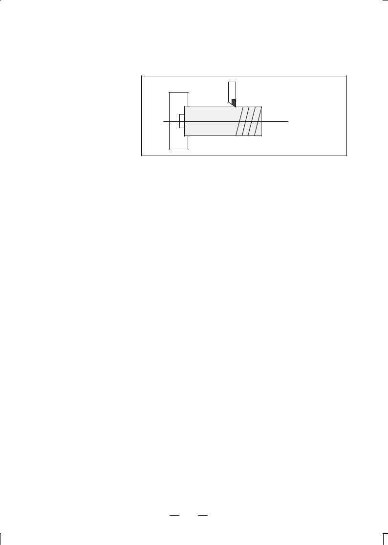
1.2
FEED±
FEED FUNCTION
Movement of the tool at a specified speed for cutting a workpiece is called the feed.
Chuck |
Tool |
Workpiece
Fig. 1.2 (a) Feed function
Feedrates can be specified by using actual numerics.
For example, the following command can be used to feed the tool 2 mm while the workpiece makes one turn :
F2.0
The function of deciding the feed rate is called the feed function (See II±5).
15
1. GENERAL |
PROGRRAMING |
B±62444E/03 |
|
|
|
1.3
PART DRAWING AND TOOL
MOVEMENT
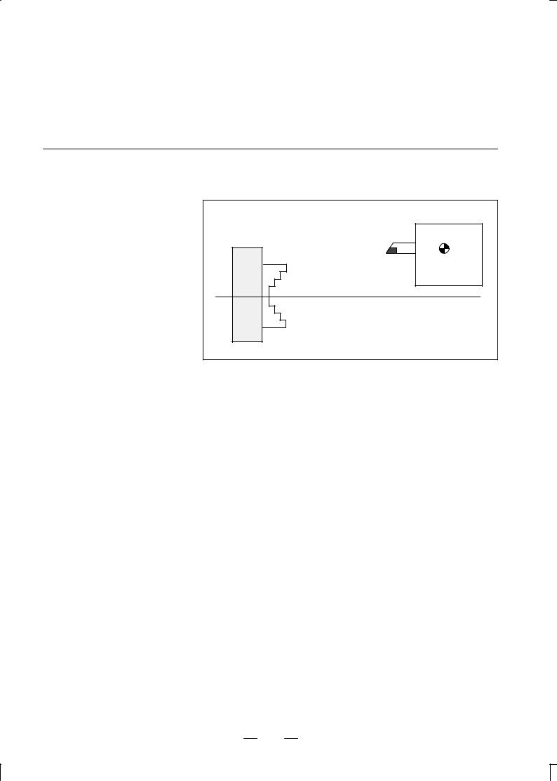
1.3.1
Reference Position (Machine±Specific Position)
A CNC machine tool is provided with a fixed position. Normally, tool change and programming of absolute zero point as described later are performed at this position. This position is called the reference position.
|
Tool post |
Chuck |
Reference |
|
|
|
position |
Fig. 1.3.1 (a) Reference position
Explanations |
The tool can be moved to the reference position in two ways: |
1.Manual reference position return (See III±3.1)
Reference position return is performed by manual button operation.
2.Automatic reference position return (See II±6)
In general, manual reference position return is performed first after the power is turned on. In order to move the tool to the reference position for tool change thereafter, the function of automatic reference position return is used.
16

B±62444E/03 |
PROGRAMMING |
1. GENERAL |
1.3.2 |
|
|
Coordinate System on |
|
|
Part Drawing and |
X |
X |
Coordinate System |
Program |
|
Specified by CNC ± |
|
|
Z |
|
|
Coordinate System |
|
|
|
|
|
|
|
Z |
|
|
Coordinate system |
|
Part drawing |
CNC |
|
|
|
|
Command |
|
|
X |
|
|
Workpiece |
|
|
|
Z |
|
Machine tool |
|
|
Fig. 1.3.2 (a) Coordinate system |
|
Explanations
Coordinate system |
The following two coordinate systems are specified at different locations: |
|
(See II±8) |
1.Coordinate system on part drawing
The coordinate system is written on the part drawing. As the program data, the coordinate values on this coordinate system are used.
2.Coordinate system specified by the CNC
The coordinate system is prepared on the actual machine tool. This can be achieved by programming the distance from the current position of the tool to the zero point of the coordinate system to be set.
230
300
Program zero point
Present tool position
Distance to the zero point of a coordinate system to be set
Fig. 1.3.2 (b) Coordinate system specified by the CNC
17
1. GENERAL |
PROGRRAMING |
B±62444E/03 |
|
|
|
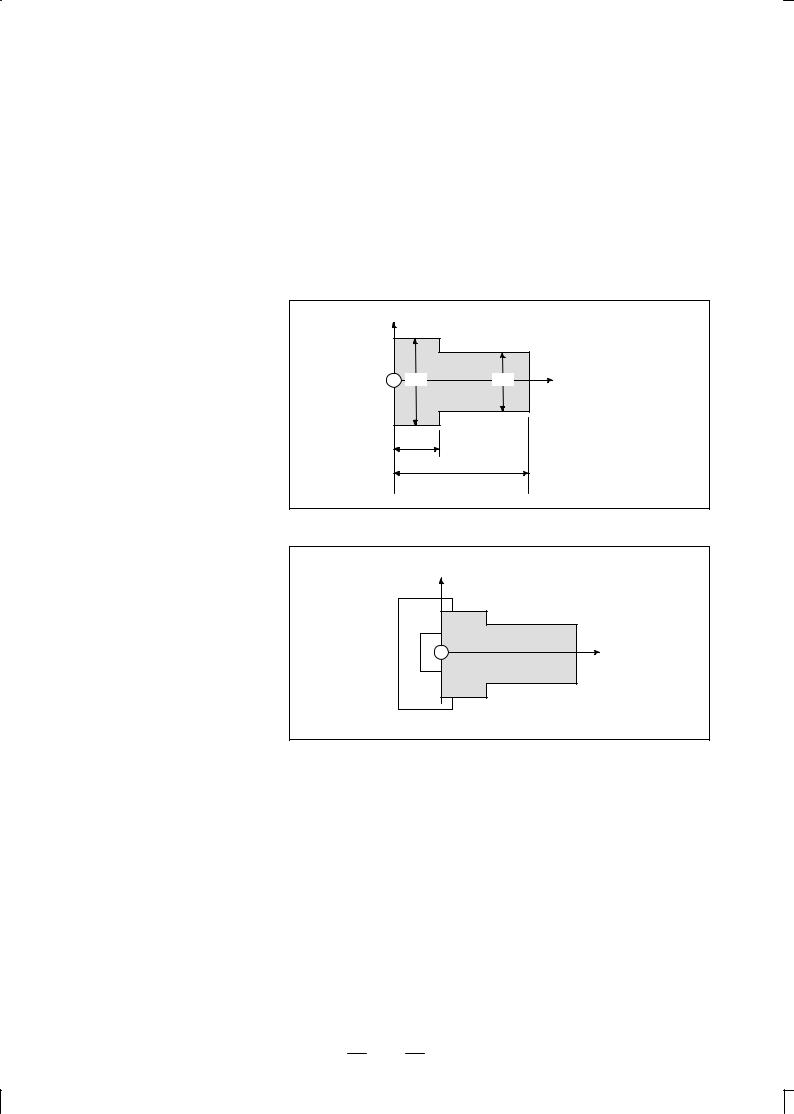
Methods of setting the two coordinate systems in the same position
The tool moves on the coordinate system specified by the CNC in accordance with the command program generated with respect to the coordinate system on the part drawing, and cuts a workpiece into a shape on the drawing.
Therefore, in order to correctly cut the workpiece as specified on the drawing, the two coordinate systems must be set at the same position.
The following method is usually used to define two coordinate systems at the same location.
1. When coordinate zero point is set at chuck face
X |
|
|
|
Workpiece |
|
60 |
40 |
Z |
40
150
Fig. 1.3.2 (c)Coordinates and dimensions on part drawing
X
Workpiece
Z
Fig. 1.3.2 (d)Coordinate system on lathe as specified by CNC
(made to coincide with the coordinate system on part drawing)
18

B±62444E/03 |
PROGRAMMING |
1. GENERAL |
|
|
|
2. When coordinate zero point is set at work end face.
X 
60 Workpiece 30
Z
 30
30 
80
100
Fig. 1.3.2 (e) Coordinates and dimensions on part drawing
X
Workpiece |
Z |
|
Fig. 1.3.2 (f) Coordinate system on lathe as specified by CNC (made to coincide with the coordinate system on part drawing)
19
1. GENERAL |
PROGRRAMING |
B±62444E/03 |
|
|
|
1.3.3
How to Indicate Command Dimensions for Moving the Tool ± Absolute, Incremental Commands
Explanations
Absolute command
Methods of command for moving the tool can be indicated by absolute or incremental designation (See II±9.1).
The tool moves to a point at ºthe distance from zero point of the coordinate systemº that is to the position of the coordinate values.
|
|
Tool |
X |
|
A |
Workpiece |
B |
|
|
|
|
φ30 |
|
Z |
70 |
|
|
|
110 |
|
Command specifying movement from point A to point B |
||
G90X30.0Z70.0; |
|
|
 Coordinates of point B
Fig. 1.3.3 (a) Absolute command
20
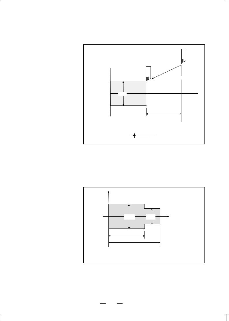
B±62444E/03 |
PROGRAMMING |
1. GENERAL |
|
|
|
Incremental command Specify the distance from the previous tool position to the next tool position.
Tool
 A
A
X 
φ60
B
Z
φ30
40
Diameter programming / radius programming
Command specifying movement from point A to point B
U±30.0W±40.0
Distance and direction for movement along each axis
Fig. 1.3.3 (b) Incremental command
Dimensions of the X axis can be set in diameter or in radius. Diameter programming or radius programming is employed independently in each machine.
1.Diameter programming
In diameter programming, specify the diameter value indicated on the drawing as the value of the X axis.
X |
|
|
B |
|
|
Workpiece |
A |
|
|
|
|
φ40 |
φ30 |
Z |
60 |
|
|
80 |
|
|
Coordinate values of points A and B |
|
|
A(30.0, 80.0), B(40.0, 60.0) |
|
|
Fig. 1.3.3 (c) Diameter programming
21
Loading...