


15 i A
Table of contents
 Loading...
Computer Numerical Control Products
GE Fanuc Automation
Series 15i / 150i – Model A
Remote Buffer
Descriptions Manual
B-6322EN-1/01 1999

Warnings and notices for
this publication
GFLE-003
Warning
In this manual we have tried as much as possible to describe all the various
matters. However, we cannot describe all the matters which must not be done,
or which cannot be done, because there are so many possibilities.
Therefore, matters which are not especially described as possible in this
manual should be regarded as “impossible”.
Notice
This document is based on information available at the time of its publication. While efforts have
been made to be accurate, the information contained herein does not purport to cover all details or
variations in hardware or software, nor to provide every contingency in connection with
installation, operation, or maintenance. Features may be described herein which are not present in
all hardware and software systems. GE Fanuc Automation assumes no obligation of notice to
holders of this document with respect to changes subsequently made.
GE Fanuc Automation makes no representation or warranty, expressed, implied, or statutory with
respect to, and assumes no responsibility for accuracy, completeness, sufficiency, or usefulness of
the information contained herein. No warranties of merchantability or fitness for purpose shall
apply.
The following are Registered Trademarks of GE Fanuc Automation
CIMPLICITY® Genius®
The following are Trademarks of GE Fanuc Automation
Alarm Master
CIMSTAR
Field Control
Genet
Helpmate
LogicMaster
Modelmaster
PowerMotion
ProLoop
PROMACRO
Series Five
Series 90
Series One
Series Six
Series Three
VuMaster
Workmaster
© Copyright 1998 FANUC Ltd.
Authorized Reproduction GE Fanuc Automation Europe S.A.
All Rights Reserved
No part of this manual may be reproduced in any form.
All specifications and designs are subject to change without notice.

B-63322EN-1/01 PREFACE
p-1
PREFACE
Applicable product name
The models covered by this manual, and their abbreviations are:
Product name Abbreviations
FANUC Series 15i-MA 15i-MA Series 15i
FANUC Series 150i-MA 150i-MA Series 150i
Related manuals
The table below lists manuals related to MODEL A of Series 15i, and
Series 150i. In the table, this manual is marked with an asterisk (*).
Table 1 (a) Related manuals
Manual name
Specification
number
DESCRIPTIONS B-63322EN
CONNECTION MANUAL (Hardware) B-63323EN
CONNECTION MANUAL (Function) B-63323EN-1
OPERATOR’S MANUAL (PROGRAMMING)
for Machining Center
B-63324EN
OPERATOR’S MANUAL (OPERATION)
for Machining Center
B-63324EN-1
MAINTENANCE MANUAL B-63325EN
PARAMETER MANUAL B-63330EN
DESCRIPTIONS (Supplement for Remote Buffer) B-63322EN-1 *

B-63322EN-1/01
c-1
CONTENTS
PREFACE ................................................................................................................ p-1
1. GENERAL.............................................................................................................1
2. INTERFACE BETWEEN REMOTE BUFFER AND
HOST COMPUTER.............................................................................................2
2.1 ELECTRICAL INTERFACE ..................................................................................................... 3
2.2 SOFTWARE INTERFACE........................................................................................................ 4
3. ELECTRICAL INTERFACE.............................................................................5
3.1 TRANSMISSION SYSTEM....................................................................................................... 6
3.2 RS-232-C INTERFACE.............................................................................................................. 7
3.3 RS-422 INTERFACE................................................................................................................ 10
4. PROTOCOL A....................................................................................................13
4.1 MESSAGE FORMAT .............................................................................................................. 14
4.2 CODE SYSTEM....................................................................................................................... 14
4.3 COMMUNICATION SYSTEM............................................................................................... 15
4.4 COMMAND ............................................................................................................................. 17
4.4.1 Command Table.............................................................................................................................17
4.4.2 Description of Data Part.................................................................................................................19
4.5 PARAMETER TABLE............................................................................................................. 23
4.6 ERROR PROCESS................................................................................................................... 24
4.7 STATUS TRANSITION........................................................................................................... 25
5. EXPANSION PROTOCOL A...........................................................................26
5.1 COMMUNICATION SYSTEM............................................................................................... 27
5.2 DATA PACKET FORMAT ..................................................................................................... 28
5.3 MONITOR PACKET FORMAT.............................................................................................. 30
5.4 COMMUNICATION EXAMPLE............................................................................................ 32
6. PROTOCOL B....................................................................................................41
6.1 COMMUNICATION SYSTEM............................................................................................... 42
6.1.1 When the CNC Alarm/Reset is not Posted to the Host...................................................................42
6.1.2 When the CNC Alarm/Reset is Posted to the Host.........................................................................44
6.2 CONTROL CODE.................................................................................................................... 48
6.3 BUFFER CONTROL................................................................................................................ 48
6.4 ALARM AND RESET OF CNC.............................................................................................. 49
7. EXPANSION PROTOCOL B (RS-422)...........................................................50

CONTENTS B-63322EN-1/01
c-2
8. DATA INTERFACE ..........................................................................................51
8.1 DATA PART ............................................................................................................................ 52
8.2 INTERFACE OF DATA PART ............................................................................................... 52
9. BINARY INPUT OPERATION FUNCTION .................................................53
9.1 FUNCTION EXPLANATION ................................................................................................. 54
9.2 TRANSFER RATE................................................................................................................... 57
9.3 NOTES......................................................................................................................................58
10. PARAMETER.....................................................................................................59
10.1 INPUT DEVICE NUMBER..................................................................................................... 60
10.2 EXCLUSIVE PARAMETER FOR REMOTE BUFFER......................................................... 61
10.3 PARAMETERS RELATED TO BINARY INPUT OPERATION.......................................... 67
11. ALARM ...............................................................................................................70
12. MAINTENANCE................................................................................................71
12.1 LED INDICATIONS ................................................................................................................ 71
12.1.1 Normal State ..................................................................................................................................71
12.1.2 System Errors.................................................................................................................................72
12.2 MATERIAL FOR REMOTE BUFFER TROUBLESHOOTING............................................ 74
12.3 DETERMINING THE LOGICAL SLOT NUMBER OF
THE REMOTE BUFFER BOARD .......................................................................................... 76
12.3.1 Determining the Logical Slot Number on the Screen Displayed
at the Time a System Alarm Occurs......................................................................................76
12.3.2 Determining the Logical Slot Number on the System Configuration Screen.........................77

B-63322EN-1/01 1. GENERAL
-1-
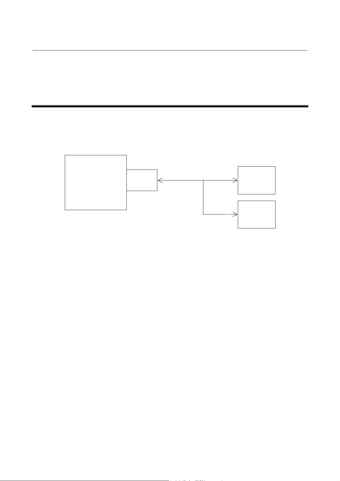
1 GENERAL
The remote buffer for FANUC Series 15i/150i-MODEL A is an
option and is used to allow a large number of data to be continuously
supplied to the CNC at high speed by connecting it to the host
computer or I/O device through a serial interface.
The followings can be performed by the remote buffer.
1) It is used to perform DNC operation at high speed and with high
reliability by performing on-line connection to the host
computer.
2) It is used to download the NC program and parameters from the
host computer. When protocol B or expansion protocol B is
used, NC programs and parameters can also be uploaded to the
host computer.
3) It is used to perform DNC operation and download various kinds
of data by connecting to the I/O device. The following I/O
devices can be connected.
(1) FANUC PROGRAM FILE Mate
(2) FANUC HANDY FILE
Hereafter, the destination where the remote buffer is connected to is
called “Host computer” for ease of explanation.
RS-232-C/RS-422
15i/150i-MA
Remote
buffer
Host
computer
I/O device

2. INTERFACE BETWEEN REMOTE BUFFER AND HOST COMPUTER B-63322EN-1/01
-2-
2 INTERFACE BETWEEN REMOTE BUFFER
AND HOST COMPUTER

B-63322EN-1/01 2. INTERFACE BETWEEN REMOTE BUFFER AND HOST COMPUTER
-3-
2.1
ELECTRICAL INTERFACE
The following which interfaces are provided as standard
specifications.
1) RS-232-C interface
2) RS-422 interface (Note 1)
RS-232-C RS-422
Interface Serial voltage interface
(start-stop system)
Balance transmission serial
interface (start-stop system)
Baud rate 50 – 19200 baud rate
(Note 2)
50 – 86400 baud rate
(Note 1)
Cable length
(MAX.)
100m (4800 baud or less)
50m (9600 baud)
15m (19200 baud)
It differs depending on I/O
devices.
Approximately 800m
(9600 baud or less)
50m (19200 baud or more)
NOTE
1 When the baud rate exceeding 38400 BPS is used, the
synchronization of reception clock is required. Prepare
the TT (*TT ) and RT (*RT) signals.
2 When t he baud r at e used is 19200 baud or more, use the
RS-422 interface.

2. INTERFACE BETWEEN REMOTE BUFFER AND HOST COMPUTER B-63322EN-1/01
-4-
2.2
SOFTWARE INTERFACE
The following four protocols for communication between the remote
buffer and host computer are provided. The protocol meeting the
requirement of specifications of connection device can be selected by
setting a parameter.
Protocol Features of protocol
Interface
used
Transfer
rate (Max.)
RS-232-C 19200 BPSProtocol
A
It is the handshake system
where transmit/receive is
repeated between the both.
RS-422 86400 BPS
Expansion
protocol
A
It is nearly the same as the
protocol A. However, the NC
program can be transferred at
high-speed so that it can be
applied to the high-speed DNC
operation.
RS-422 86400 BPS
Protocol
B
It is the system for controlling
the communication between the
both by the control code output
from the remote buffer.
RS-232-C 19200 BPS
Expansion
protocol
B
The control system is the same
as that of protocol B. However,
it allows the transmission speed
to be increased. In this case, it
is required to receive the
reception synchronization clock
from the source.
RS-422 86400 BPS
NOTE
The average data transfer speed becomes smaller than
the maximum transfer speed.

B-63322EN-1/01 3. ELECTRICAL INTERFACE
-5-
3 ELECTRICAL INTERFACE
3. ELECTRICAL INTERFACE B-63322EN-1/01
-6-
3.1
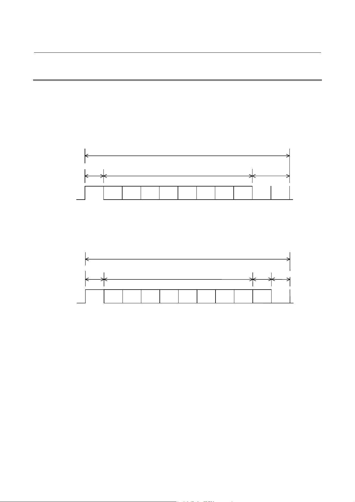
TRANSMISSION SYSTEM
It is the start-stop system for adding the start bit before and stop bit
after the information bits, respectively.
The format for adding one parity bit to each byte of data to be
transmitted is also allowed.
1) Format with no parity bit
Data bit is sent starting from the LSB.
2) Format with parity bit
Data bit is sent starting from the LSB.
The format with parity bit becomes the even parity including a
parity bit. The number of stop bits of parameter determines
whether there is a parity bit or not.
Stop bit 1 → With parity bit
Stop bit 2 → With no parity bit
b1 b2 b5b4b3 b8b7b6
1 character
Start bit Stop bit
Data bit
ON
OFF
LSB MSB
pb1 b2 b5b4b3 b8b7b6
1 character
Start bit
Data bit
ON
OFF
LSB MSB
Stop bit
Parity bit
B-63322EN-1/01 3. ELECTRICAL INTERFACE
-7-
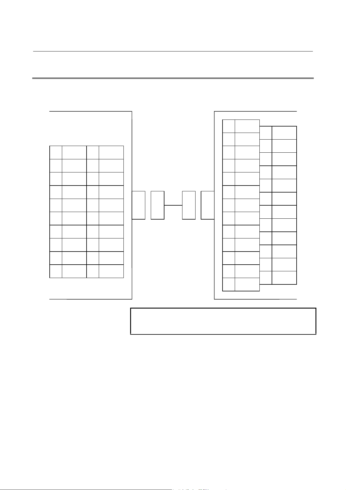
3.2
RS-232-C INTERFACE
1) Connection between devices
NOTE
(+24V) is used as the power to FANUC RS-232-C
devices.
JD5L
(PCR-E20LMDETZ-SL)
(DBM-25S)
Host compute r (e xample)
1 RD
2 0V
3 DR
4 0V
5 CS
6 0V
7 CD
8 0V
9
10 (+24V)
11 SD
12 0V
13 ER
14 0V
15 RS
16 0V
17
18
19 (+24V)
20
1 FG
2 SD
3 RD
4 RS
5 CS
6 DR
7 SG
8 CD
9
10
11
12
13
14
15
16
17
18
19
20 ER
21
22
23
24
25
CNC
remote buffer board
3. ELECTRICAL INTERFACE B-63322EN-1/01
-8-
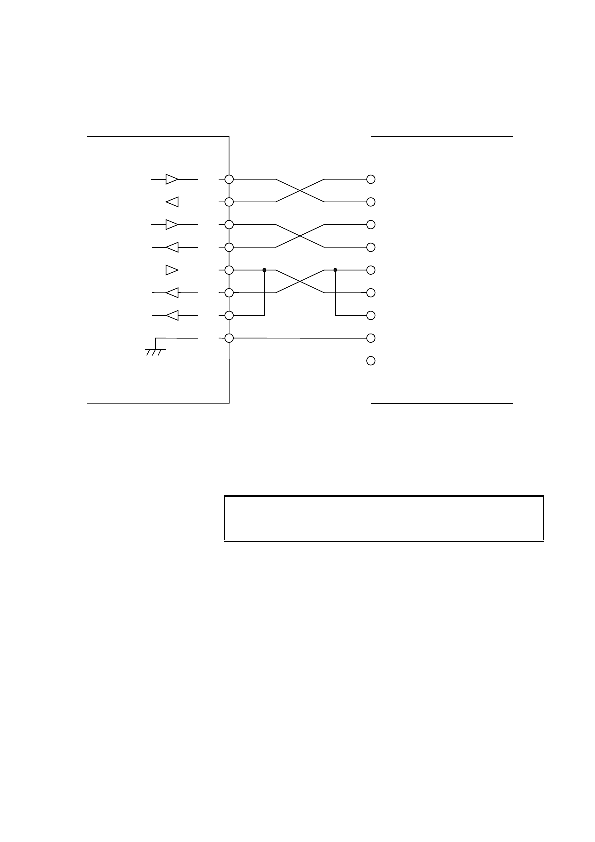
2) General diagram of signal connection
When no CS is used, short-circuit it with the RS. However,
when the protocol A or expansion protocol A is used, perform
connecting as shown in the figure above for use as busy control.
When DR is not used, short-circuit it with ER.
Always short-circuit CD to ER.
NOTE
Connect the FG pin to the FG pin of the relay connector
or to the protective grounding pin inside t he locker.
Host compute r
CNC
Output
Input
SD
RD
RS
CS
ER
DR
CD
0V
11
1
15
5
13
3
7
SD
RD
RS
CS
ER
DR
CD
SG
FG Note)
B-63322EN-1/01 3. ELECTRICAL INTERFACE
-9-
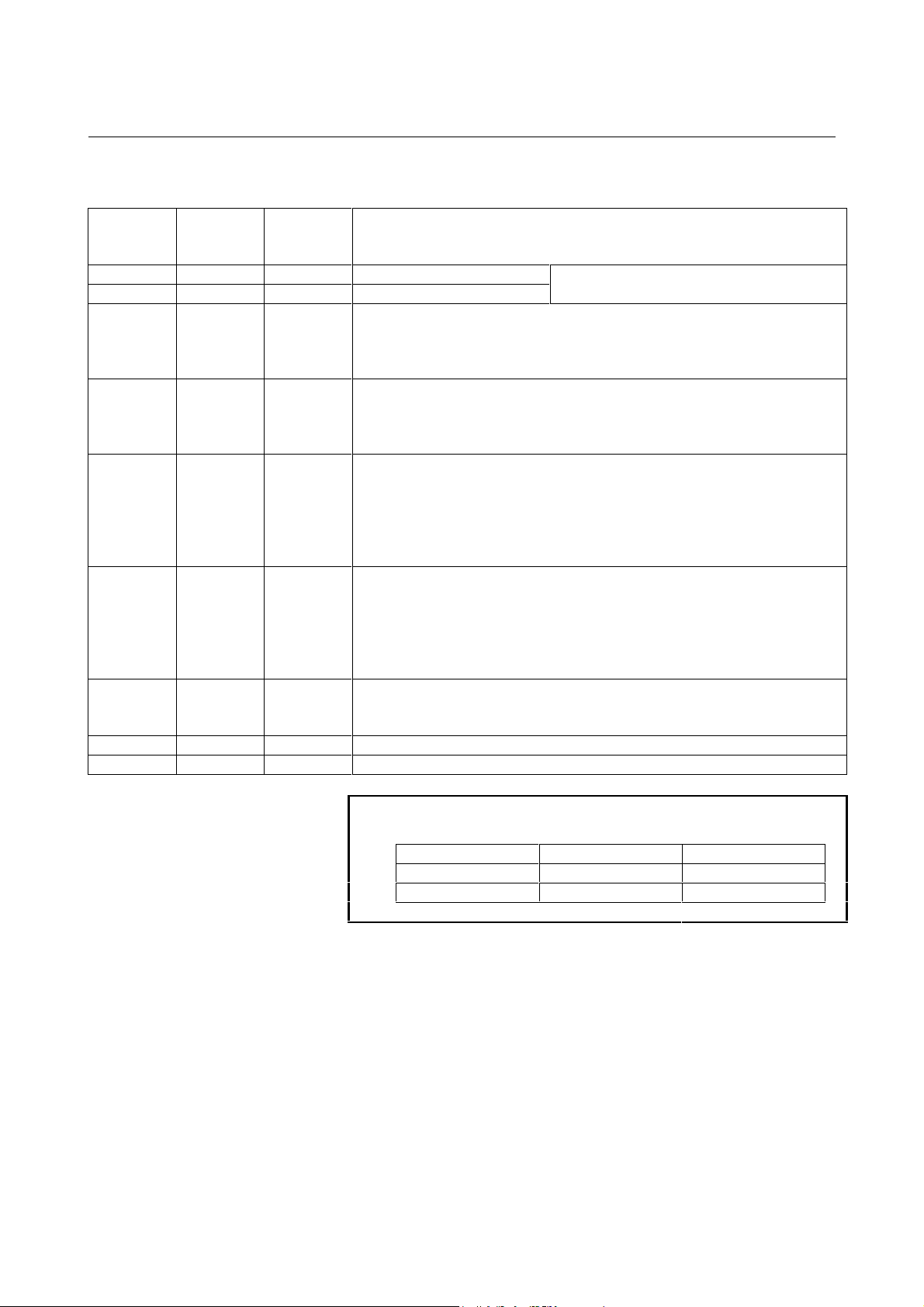
3) Signal description
Signal
name
RS-232-C
circuit
number
Input/
output
Description
SD 103 Output Send data
RD 104 Input Receive data
See “3.1” for the bit configuration.
RS 105 Output Request to send
It is used to inform whether the remote buffer is ready to receive data or not.
When the ER signal is on and this signal is on, the remote buffer is ready to
receive data.
CS 106 Input Clear to send
It is used to know the busy status at the host computer. When the DR signal
is on and this signal is on, the host computer is regarded as being ready to
receive data.
DR 107 Input Data set ready
When this signal is on, it is considered that the preparation at the host
computer has been completed. Generally, it is connected to the ER signal of
the host computer. When this signal is off during data transmission, an
alarm occurs.
Always connect it to the ER signal of CNC side when this signal is not used.
ER 108.2 Output Data terminal ready
When this signal is on, it is considered that the remote buffer is in ready
condition.
In general, it is connected to the ER signal at the host computer. If it is
turned off during transmission of data, an alarm occurs. If this signal is not
used, always connect this to the ER signal at the CNC side.
CD 109 Input Received line signal detector
This signal is not used for connection to the host computer. Thus, connect it
to the ER signal of remote buffer side.
SG 102 Grounding for signal
FG 101 Grounding for protection
NOTE
Turn on or off signal according to the following:
-3 V or less +3 V or more
Function OFF ON
Signal Condition Marking Spacing

3. ELECTRICAL INTERFACE B-63322EN-1/01
-10-
3.3
RS-422 INTERFACE
1) Connection between devices
NOTE
Do not connect anything to the (+24V) pin.
JD6L
(PCR-E20LMDETZ-SL)
Host compute r (e xample)
1 RD
2 *RD
3 RT
4 *RT
5 CS
6 *CS
7 RR
8 0V
9 *RR
10 (+24V )
11 SD
12 *SD
13 TT
14 *TT
15 RS
16 *RS
17 TR
18 *TR
19 (+24V)
20
1 FG
2
3
4 SD
5
6 RD
7 RS
8 RT
9 CS
10
11 RR
12 TR
13
20
21
22 *SD
23
24 *RD
25 *RS
26 *RT
27 *CS
28
29 *RR
30 *TR
31
CNC
remote buffer board
14
15
16
17 TT
18
19 SG
33
34
35 *TT
36
37
32
B-63322EN-1/01 3. ELECTRICAL INTERFACE
-11-
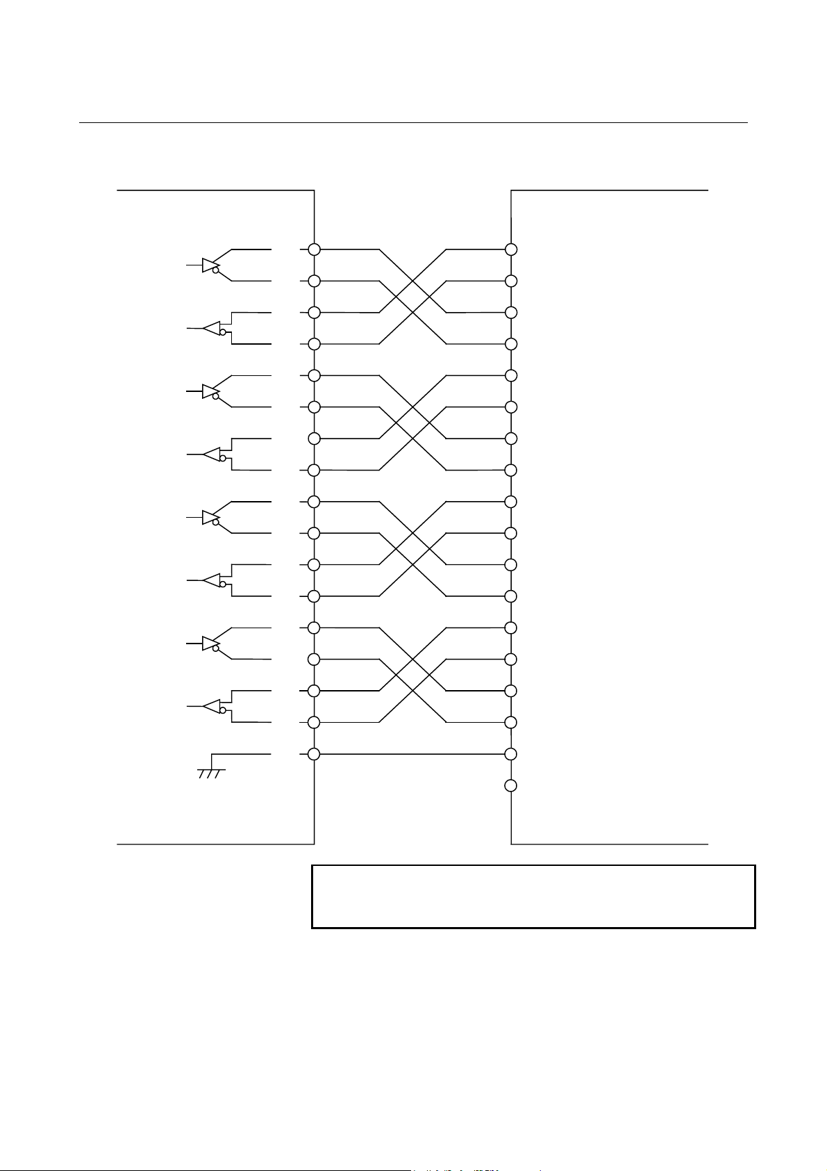
2) General diagram of signal connection
NOTE
Connect the FG pin to the FG pin of the relay connector
or to the protective grounding pin inside t he locker.
Host compute r
CNC
Output
Input
SD
*SD
RD
*RD
RS
*RS
CS
0V
11
12
1
2
15
16
5
SD
*SD
RD
*RD
RS
*RS
CS
SG
FG Note)
*CS
TR
*TR
RR
*RR
TT
*TT
6
17
18
7
9
13
14
*CS
TR
*TR
RR
*RR
TT
*TT
RT
*RT
4
8
RT
*RT
3
3. ELECTRICAL INTERFACE B-63322EN-1/01
-12-
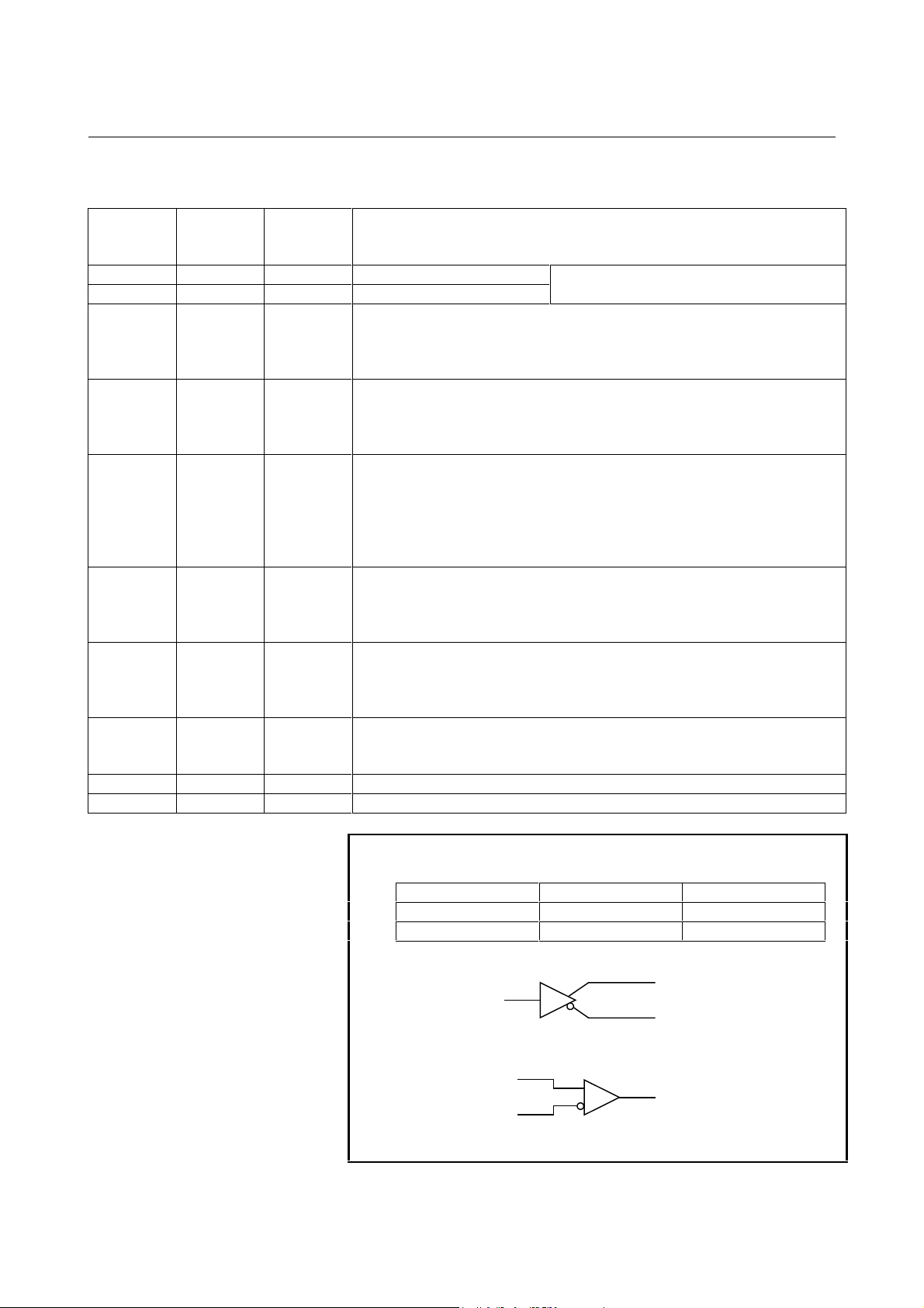
3) Signal description
Signal
name
RS-232-C
circuit
number
Input/
output
Description
SD 103 Output Transmission data
RD 104 Input Reception data
See “3.1” for the bit configuration.
RS 105 Output Transmission request
It is used to inform whether the remote buffer is ready to receive data or not.
When the TR signal is on and this signal is on, the remote buffer is ready to
receive data.
CS 106 Input Clear to send
It is used to know the busy status at the host computer. When the RR signal
is on and this signal is on, the host computer is regarded as being ready to
receive data.
TR
(ER)
108.2 Output Terminal Ready
When this signal is on, it is considered that the operation of remote buffer
has been completed.
In general, it is connected to the ER signal at the host computer. If it is
turned off during transmission of data, an alarm results. If this signal is not
used, always connect this to the ER signal at the CNC side.
RR
(DR)
109 Input Receiver Ready
When this signal is on, it indicates that the host computer is ready to transmit
data to the remote buffer. If this signal is not used, always connect it to the
TR signal at the remote buffer side.
TT 113 Output Transmission timing
Transmission clock transmission terminal at the remote buffer side. When
38400 baud or more is used, always connect it to the RT signal at the host
computer side.
RT 115 Input Reception timing
Reception clock input terminal at the remote buffer side. When 38400 baud
or more is used, always connect it to the TT signal at the host computer side.
SG 102 Grounding for signal
FG 101 Grounding for protection
NOTE
The signal turn on/of f according to the following:
A < B A > B
Function OFF ON
Signal Condition Marking Spacing
Driver
Receiver
A
A
B
B

B-63322EN-1/01 4. PROTOCOL A
-13-
4 PROTOCOL A
It is used for the handshake system where the communication between
the remote buffer and host computer repeats transmission/reception
each other.
4. PROTOCOL A B-63322EN-1/01
-14-
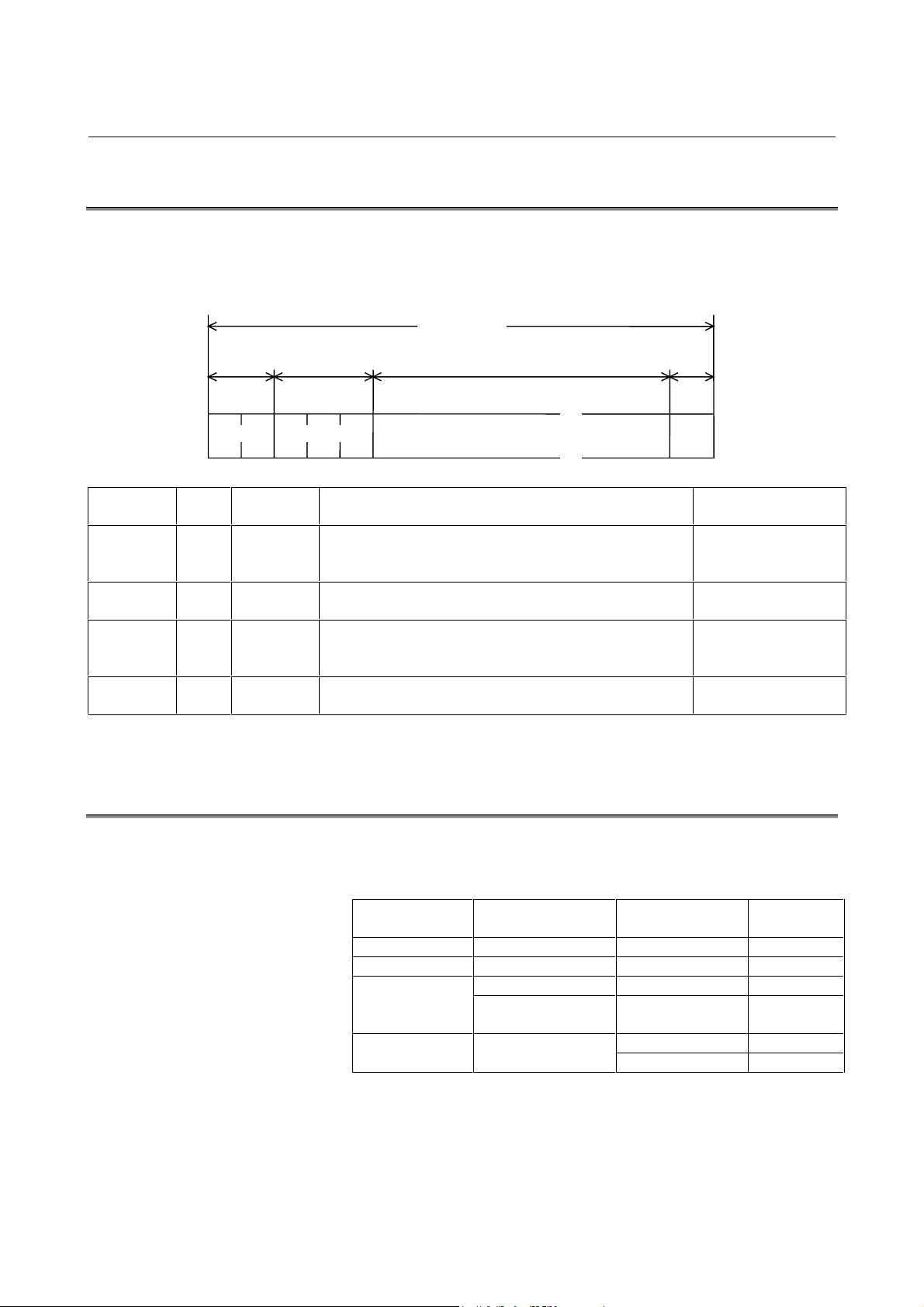
4.1
MESSAGE FORMAT
The information (character-string) exchanged between the remote
buffer and host computer is called “message”. The general type of
message is shown as below:
Field
Byte
length
Abbreviation Meaning Remarks
Checksum 2 No It is used to indicate the lower 8 bits of binary sum of all
bytes from the command field to end code by two-digit
hexadecimal number (0 – 9 and A – F).
Transmit the MSB
before the LSB.
Command 3 No It is used to display the type of message (functions) and
to specify the operation and response of the partner.
Data 0 – n Yes It is the data part corresponding to a command.
Abbreviate it when a command without data part is used.
Details are described later.
SAT, SET, DAT, RTY
SDI, SDO
End code
(ETX)
1 No It indicates the end of message. Not transmit a code
which is the same as an end code to data part.
4.2
CODE SYSTEM
The communication codes between the remote buffer and host
computer are described below:
Field Command Code
Related
parameters
Checksum --- ISO/ASCII 5000#2
Command name --- ISO/ASCII 5000#2
DAT ISO/ASCII/EIA/Bin 0000#2Data part
Commands other
than DAT
ISO/ASCII 5000#2
ISO/ASCII 5000#2End code ---
CR/ETX 5000#3
Sum Command Data part
/
/
ETX
1 byte
Variable length (it can be omitted.)3 byte2 byte
Message
B-63322EN-1/01 4. PROTOCOL A
-15-
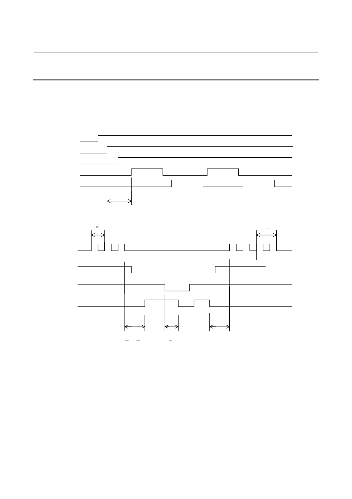
4.3
COMMUNICATION SYSTEM
It is used to perform communication between the remote buffer and
host computer. When the both are ready to operate after power on,
the communication starts from the transmission of remote buffer and
reception of host computer and then the transmission/reception is
repeated.
(1) Approximately two seconds are required for the first request
after both of remote buffer and host computer are ready.
However, when the CS signal is off, the first transmission is
performed after turning on the CS signal.
(2) The minimum time period between bytes is determined by the
parameter Ti (msec) of SET command. There is no prescription
of minimum time period between reception bytes.
(3) Switching from transmission to reception
Immediately the remote buffer side can be ready to receive
signal. Start transmission within the parameter setting time (To
sec) at the host computer side. When no response is obtained for
the time period (To or more), an error occurs in the host
computer. (Overtime)
ER
RS
CS
SD
RD
Approximately 2 seconds
0 < t2 < To n2 < No
Tx<t3<tp
n2t2 t3
t1 > ti
n1 < 3
SD
CS
RS
RD

4. PROTOCOL A B-63322EN-1/01
-16-
(4) Switching from reception to transmission
The remote buffer waits for Tx msec (parameter setting time)
and moves to the transmission process after completion of
reception. When there is no transmission after waiting another
parameter (Tp seconds), it is considered that an error occurred in
the remote buffer.
(5) Overrun on reception
When the RS signal is turned off by the remote buffer on
reception of signal, stop the transmission within the overrun
parameter number bytes by the host computer.
(6) Overrun on transmission
When the CS is turned off on transmission of remote buffer, the
transmission is suspended within 3 bytes including that which is
currently being transmitted.

B-63322EN-1/01 4. PROTOCOL A
-17-
4.4
COMMAND
4.4.1
Command Table
Commands used in the protocol A are described below:
Origin station R: Remote buffer H: Hoast computer
Command
Origin
station
Functions Data part
Executed command
at CNC side
R Initialization command
It is used to command the initialization of host.
Meaningless SYNSYN
H Response of SYN
Response when the initialization does not end yet
Initialization command
It is command to initialize the remote buffer.
Meaningless
R Notice of initialization end
The host should respond the RDY in the case of end
of initialization or the SYN when the initialization has
not ended.
Meaningless RDY, SYN
RDY
H Notice of initialization end
It is used to notice that the initialization of host has
ended.
Meaningless
RST R Notice of CNC reset
Immediately after the CNC is res et, transmit this
command when it is possible to transmit signal.
Meaningless ARS
ARS H Response corresponding to the RST Meaningless
ALM R Notice of CNC alarm occurrence
When an alarm occurs in CNC, trans mit this
command when it is possible to transmit immediately
after that.
Meaningless AAL
AAL H Response corresponding to the ALM Meaningless
SAT R Notice of remote buffer status
It is used to notice the status of remote buffer by
transmitting it when there is no data to be especially
transmitted while the Tp sec has passed after
receiving the command.
Status SET......... Normal
CLB
RDI
SDO
SYN
SET H Response corresponding to the SAT
It is used to modify the setting parameter of remote
buffer by specifying the data part.
Modification
parameter
GTD R Transmit command of NC data
Transmit this command when the space of remote
buffer exceeds Nb bytes of parameter setting value
in the remote operation status.
Meaningless DAT ........ Normal
EOB........ End
WAT ....... Busy
RDI
SDO
DAT H Response corresponding to the GTD
Transmit this command with the NC data.
NC data
WAT H Response corresponding tot he GTD
Transmit this command if the NC data cannot be
transmitted within To when the GTD has been
received.
The GTD is transmitted again by the remote buffer
after a parameter setting time of Tw.
Meaningless

4. PROTOCOL A B-63322EN-1/01
-18-
Command
Origin
station
Functions Data part
Executed command
at CNC side
EOD H Response corresponding to GTD
Transmit this command when the GTD has been
received while the transmission of NC data has
been completed.
Meaningless
CLB H Buffer clear
It can be transmitted as the response of SAT when
the buffer at the remote buffer side is to be cleared.
Meaningless
RDI H DI reading request
It is used to request transmission of image of
specified 8-bit DI.
The DI image at that time is responded by the SDI
command in the remote buffer.
This command can be transmitted as responses of
SAT and GTD.
Meaningless
SDI R Notice of DI
It is used to transmit the signal status of DI as the
response of RDI command.
The host should transmit the response of command
received immediately before transmitting the RDI
after receiving this command.
DI image Response
corresponding to the
GTD/SAT
SDO H DO output request
It is used to command that the 8-bit image of data
part should be output to the DO.
It can be transmitted as responses of SAT, GTD,
and SDI.
DO image
RTY R/H Request of retransmission
It is used to request the retransmission of the same
message as before.
Immediately transmit this command when a
transmit error is detected during reception of
messages.
Reason for
retransmission
Command
transmitted
immediately before

B-63322EN-1/01 4. PROTOCOL A
-19-
4.4.2
Description of Data Part
Data part of message is of variable length. Up to 4096 and 72 bytes
can be received/transmitted in the case of <DAT> and the others,
respectively.
1) Data part of SAT
Byte
position
Meaning and code
Default value
(hexadecimal)
1 Switching of remote/tape operations
According to parameter (Data No. 5000, #1)
setting. (*C)
0
2 Status of remote buffer
0: Non-completion status of operation
preparation
1: Reset status
2: Operation status
3: Alarm status
4: Open line
0
3 Causes of shift to alarm status
0: NC alarm
1: Checksum error (retry over)
6: Reception of unexpected response
(command error)
A: Overrun error (retry over)
0
4 Not used ---
5 - 8 Number of bytes currently stored in the buffer
(Four-digit hexadecimal number)
0000
9 - 12 Current value of parameter Nb
Empty area limit of buffer
(Four-digit hexadecimal number)
07D0
13 - 16 Current value of parameter No
Amount of maximum overrun on reception
(Four-digit hexadecimal number)
0032
17 - 20 Current value of parameter No
Number of times of retry on detecting a
transmission error (Four-digit hexadecimal
number)
000A
21 - 24 Current value of parameter Tp
Polling time interval (second)
(Four-digit hexadecimal number)
0005
25 - 28 Current value of parameter To
Time-out time (second)
(Four-digit hexadecimal number)
0014
29 - 32 Current value of parameter Ti
Minimum time interval between bytes
transmitted (Four-digit hexadecimal number)
000A
33 - 36 Current value of parameter Tx
Minimum switching time from reception to
transmission (Four-digit hexadecimal number)
0064
37 - 40 Current value of parameter Tw
Waiting time on reception of (WAT)
(Four-digit hexadecimal number)
0005
4. PROTOCOL A B-63322EN-1/01
-20-
Byte
position
Meaning and code
Default value
(hexadecimal)
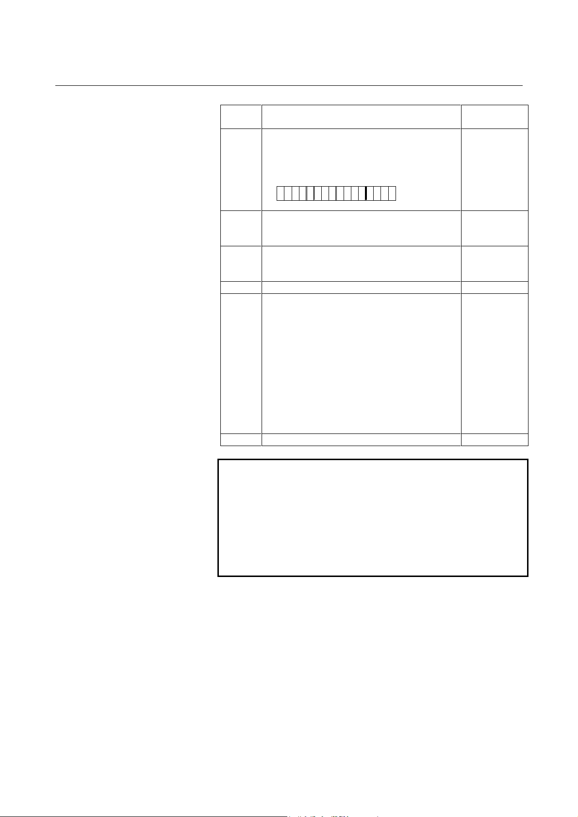
41 - 44 Unit for the boring time (four digits in
hexadecimal)
Setting parameter P
2
to 1 sets the unit for the
boring time to 0.1 seconds.
0000
45 - 46 Note)
Code to be converted (two-digit hexadecimal
number)
00
47 - 78 Note)
Code after conversion (two-digit hexadecimal
number)
00
49 - 54 Rese rve ---
55 - 56 Packet length parameter n of expansion
protocol A (two-digit hexadecimal number)
00: Normal protocol A
01: Expansion protocol A
NC data length = 256 bytes
Packet length = 260 bytes
02: Expansion protocol A
NC data length = 512 bytes
Packet length = 516 bytes
04: Expansion protocol A
NC data length = 1024 bytes
Packet length = 1028 bytes
00
57 - 72 Not used ---
NOTE
Bytes 45, 46, 47, and 48 of SAT
These bytes contain the parameters necessary for the
remote buffer t o convert the protocol A <DAT > command
data and expansion protocol A data in the specified
section. Specify the code to be converted in bytes 45
and 46. Specify the code to which conversion is to be
performed in bytes 47 and 48. For details, refer to
Section 4.4.2 (3).
15 0
0000000000000P
2
00
Loading...