


DESCRIPTIONS
B-65262EN/06

•No part of this manual may be reproduced in any form.
•All specifications and designs are subject to change without notice.
The products in this manual are controlled based on Japan’s “Foreign Exchange and Foreign Trade Law”. The export from Japan may be subject to an export license by the government of Japan.
Further, re-export to another country may be subject to the license of the government of the country from where the product is re-exported. Furthermore, the product may also be controlled by re-export regulations of the United States government.
Should you wish to export or re-export these products, please contact FANUC for advice.
The products are manufactured under strict quality control. However, when using any of the products in a facility in which a serious accident or loss is predicted due to a failure of the product, install a safety device.
In this manual we have tried as much as possible to describe all the various matters. However, we cannot describe all the matters which must not be done, or which cannot be done, because there are so many possibilities.
Therefore, matters which are not especially described as possible in this manual should be regarded as ”impossible”.

B-65262EN/06 |
SAFETY PRECAUTIONS |
SAFETY PRECAUTIONS
This “Safety Precautions” section describes the precautions which must be observed to ensure safety when using FANUC AC servo motors.
Users of any servo motor model are requested to read this "Safety Precautions" carefully before using the servo motor.
The users are also requested to read this manual carefully and understand each function of the motor for correct use.
The users are basically forbidden to do any behavior or action not mentioned in the "Safety Precautions." They are invited to ask FANUC previously about what behavior or action is prohibited.
Contents |
|
DEFINITION OF WARNING, CAUTION, AND NOTE......................................................................... |
s-1 |
WARNING................................................................................................................................................. |
s-2 |
CAUTION.................................................................................................................................................. |
s-4 |
NOTE ......................................................................................................................................................... |
s-5 |
CAUTION LABEL .................................................................................................................................... |
s-6 |
DEFINITION OF WARNING, CAUTION, AND NOTE
This manual includes safety precautions for protecting the user and preventing damage to the machine. Precautions are classified into Warning and Caution according to their bearing on safety. Also, supplementary information is described as a Note. Read the Warning, Caution, and Note thoroughly before attempting to use the machine.
 WARNING
Applied when there is a danger of the user being injured or when there is a damage of both the user being injured and the equipment being damaged if the approved procedure is not observed.
 CAUTION
Applied when there is a danger of the equipment being damaged, if the approved procedure is not observed.
NOTE
The Note is used to indicate supplementary information other than Warning and
Caution.
Those items described in CAUTION, if not observed, may lead to a serious result, depending on the situation. Each description of CAUTION provides important information. So, be sure to observe CAUTION.
- Read this manual carefully, and store it in a safe place.
s-1

SAFETY PRECAUTIONS |
B-65262EN/06 |
WARNING

 WARNING
-Be sure to ground a motor frame.
To avoid electric shocks, be sure to connect the grounding terminal in the terminal box to the grounding terminal of the machine.
-Before starting to connect a motor to electric wires, make sure they are
isolated from an electric power source.
A failure to observe this caution is vary dangerous because you may get electric shocks.
-Do not ground a motor power wire terminal or short-circuit it to another power
wire terminal.
A failure to observe this caution may cause electric shocks or a burned wiring.
*Some motors require a special connection such as a winding changeover. Refer to Chapter 7, “OUTLINE DRAWINGS” for details.
-When connecting a cord such as a power line to the terminal block, use
specified tightening torque to firmly connect the cord.
If operation is performed with a loose terminal, the terminal block can overheat, resulting in a fire. Moreover, a terminal can be detached, resulting in a ground fault, short circuit, or electric shock.
-Do not apply current when a terminal of the terminal block or the crimp
terminal of a power line is exposed.
If the hand or a conductive object touches a terminal of the terminal block or the crimp terminal of a power line, you may get electric shocks. Attach an insulation cover (accessory) onto the terminal block. Moreover, cover the crimp terminal at the tip of a power line with an insulation tube.
-Assemble and install a power connector securely.
If a power line is detached due to a failure in crimping or soldering, or a conductive area is exposed due to a failure in shell assembly, you may get electric shocks.
-Do not touch a motor with a wet hand.
A failure to observe this caution is vary dangerous because you may get electric shocks.
-Before touching a motor, shut off the power to it.
Even if a motor is not rotating, there may be a voltage across the terminals of the motor. Especially before touching a power supply connection, take sufficient precautions. Otherwise you may get electric shocks.
-Do not touch any terminal of a motor for a while (at least 5 minutes) after the
power to the motor is shut off.
High voltage remains across power line terminals of a motor for a while after the power to the motor is shut off. So, do not touch any terminal or connect it to any other equipment. Otherwise, you may get electric shocks or the motor and/or equipment may get damaged.
-On the machine, install a stop device for securing safety.
The brake built into the servo motor is not a stop device for securing safety. The machine may not be held if a failure occurs.
- Do not enter the area under the vertical axis without securing safety.
If a vertical axis drop occurs unexpectedly, you may be injured.
s-2

B-65262EN/06 |
SAFETY PRECAUTIONS |

 WARNING
-Fasten a motor firmly before driving the motor.
If a motor is driven when the motor is not fastened firmly or is fastened insufficiently, the motor can tumble or is removed, resulting in a danger. If the motor mounting section is not sufficiently strong, the machine may be damaged or the user may be injured.
-Do not get close to a rotary section of a motor when it is rotating.
When a motor is rotating, clothes or fingers can be caught, resulting in an injury.
-Do not drive a motor with an object such as a key exposed.
An object such as a key can be thrown away, resulting in an injury. Before rotating a motor, check that there is no object that is thrown away by motor rotation.
-Do not apply a radial load exceeding the "allowable radial load".
The shaft can break, and components can be thrown away. When the vertical axis is involved, a vertical axis drop can occur.
-To drive a motor, use a specified amplifier and parameters.
An incorrect combination of a motor, amplifier, and parameters may cause the motor to behave unexpectedly. This is dangerous, and the motor may get damaged.
-Make sure that the load inertia ratio is not greater than specified value.
If the motor stops from its maximum rotational speed with greater than specified load inertia ratio, the resistor element of the dynamic brake may become abnormally hot, possibly causing damage to the dynamic brake and a fire.
-Do not bring any dangerous stuff near a motor.
Motors are connected to a power line, and may get hot. If a flammable is placed near a motor, it may be ignited, catch fire, or explode.
-Be safely dressed when handling a motor.
Wear safety shoes or gloves when handling a motor as you may get hurt on any edge or protrusion on it or electric shocks.
-Use a crane or lift to move a motor from one place to another.
A motor is heavy, so that if you lift a motor by hand, you may be exposed to various risks. For example, the waist can be damaged, and the motor can drop to injure you. Use equipment such as a crane as needed. (For the weight of a motor, see Chapter 6, "SPECIFICATIONS".)
-Do not touch a motor when it is running or immediately after it stops.
A motor may get hot when it is running. Do not touch the motor before it gets cool enough. Otherwise, you may get burned.
- Be careful not get your hair or cloths caught in a fan.
Be careful especially for a fan used to generate an inward air flow.
Be careful also for a fan even when the motor is stopped, because it continues to rotate while the amplifier is turned on.
-Install the components around a motor securely.
If a component is displaced or removed during motor rotation, a danger can result.
s-3

SAFETY PRECAUTIONS |
B-65262EN/06 |
CAUTION

 CAUTION
-Use the eyebolt of a motor to move the motor only.
When a motor is installed on a machine, do not move the machine by using the eyebolt of the motor. Otherwise, the eyebolt and motor can be damaged.
-Do not disassemble a motor.
Disassembling a motor may cause a failure or trouble in it.
If disassembly is in need because of maintenance or repair, please contact a service representative of FANUC.
For pulse coder replacement, refer to the maintenance manual (B-65285EN or B-65325EN).
-Do not machine and modify a motor.
Do not machine and modify a motor in any case except when motor machining or modification is specified by FANUC. Modifying a motor may cause a failure or trouble in it.
-Do not conduct dielectric strength or insulation test for a sensor.
Such a test can damage elements in the sensor.
-Be sure to connect motor cables correctly.
An incorrect connection of a cable cause abnormal heat generation, equipment malfunction, or failure. Always use a cable with an appropriate current carrying capacity (or thickness). For how to connect cables to motors, refer to Chapter 7, “OUTLINE DRAWINGS”.
-Do not apply shocks to a motor or cause scratches to it.
If a motor is subjected to shocks or is scratched, its components may be adversely affected, resulting in normal operation being impaired. Plastic components and sensors can be damaged easily. So, handle those components very carefully. In particular, do not lift a motor by using a plastic component, connector, terminal block, and so forth.
-Do not step or sit on a motor, and do not put a heavy object on a motor.
If you step or sit on a motor, it may get deformed or broken. Do not put a motor on another unless they are in packages.
-When attaching a component having inertia, such as a pulley, to a motor,
ensure that any imbalance between the motor and component is minimized.
If there is a large imbalance, the motor may vibrates abnormally, resulting in the motor being broken.
-Be sure to attach a key to a motor with a keyed shaft.
If a motor with a keyed shaft runs with no key attached, it may impair torque transmission or cause imbalance, resulting in the motor being broken.
-Use a motor under an appropriate environmental condition.
Using a motor in an adverse environment may cause a failure or trouble in it. Refer to Chapter 3, “USAGE” for details of the operating and environmental conditions for motors.
-Do not apply a commercial power source voltage directly to a motor.
Applying a commercial power source voltage directly to a motor may result in its windings being burned. Be sure to use a specified amplifier for supplying voltage to the motor.
s-4

B-65262EN/06 |
SAFETY PRECAUTIONS |

 CAUTION
-Do not use the brake built into a motor for braking.
The brake built into a servo motor is designed for holding. If the brake is used for braking, a failure can occur.
-Ensure that motors are cooled if they are those that require forcible cooling.
If a motor that requires forcible cooling is not cooled normally, it may cause a failure or trouble. For a fan-cooled motor, ensure that it is not clogged or blocked with dust and dirt. For a liquid-cooled motor, ensure that the amount of the liquid is appropriate and that the liquid piping is not clogged. For both types, perform regular cleaning and inspection.
-When storing a motor, put it in a dry (non-condensing) place at room
temperature (0 to 40 °C).
If a motor is stored in a humid or hot place, its components may get damaged or deteriorated. In addition, keep a motor in such a position that its shaft is held horizontal and its terminal box is at the top.
-FANUC motors are designed for use with machines. Do not use them for any
other purpose.
If a FANUC motor is used for an unintended purpose, it may cause an unexpected symptom or trouble. If you want to use a motor for an unintended purpose, previously consult with FANUC.
NOTE
NOTE
-Ensure that a base or frame on which a motor is mounted is strong enough.
Motors are heavy. If a base or frame on which a motor is mounted is not strong enough, it is impossible to achieve the required precision.
-Do not remove a nameplate from a motor.
If a nameplate comes off, be careful not to lose it. If the nameplate is lost, the motor becomes unidentifiable, resulting in maintenance becoming impossible.
-When testing the winding or insulation resistance of a motor, satisfy the
conditions stipulated in IEC60034.
Testing a motor under a condition severer than those specified in IEC60034 may damage the motor.
-For a motor with a terminal box, make a conduit hole for the terminal box in a
specified position.
When making a conduit hole, be careful not to break or damage unspecified portions. Refer to an applicable specification manual.
-Before using a motor, measure its winding and insulation resistances, and
make sure they are normal.
Especially for a motor that has been stored for a prolonged period of time, conduct these checks. A motor may deteriorate depending on the condition under which it is stored or the time during which it is stored. For the winding resistances of motors, refer to their respective specification manuals, or ask FANUC. For insulation resistances, see the following table.
s-5
SAFETY PRECAUTIONS |
B-65262EN/06 |
NOTE
-To use a motor as long as possible, perform periodic maintenance and
inspection for it, and check its winding and insulation resistances.
Note that extremely severe inspections (such as dielectric strength tests) of a motor may damage its windings. For the winding resistances of motors, refer to Chapter 6, “SPECIFICATIONS”, or ask FANUC. For insulation resistances, see the following table.
MOTOR INSULATION RESISTANCE MEASUREMENT
Measure an insulation resistance between each winding and motor frame using an insulation resistance meter (500 VDC). Judge the measurements according to the following table. Make an insulation resistance measurement on a single motor unit after detaching cords such as a power line.
Insulation resistance |
Judgment |
|
100 MΩ or higher |
Acceptable |
|
10 to 100 MΩ |
The winding has begun deteriorating. There is no problem with the performance |
|
at present. Be sure to perform periodic inspection. |
||
|
||
1 to 10 MΩ |
The winding has considerably deteriorated. Special care is in need. Be sure to |
|
perform periodic inspection. |
||
|
||
Lower than 1 MΩ |
Unacceptable. Replace the motor. |
CAUTION LABEL
The following label is attached to the motor.
Attach this label to a prominent place on the motor to call attention to the user.
Heat caution label (compliance with the IEC standard)
Heat caution label
Since the motor is heated to a high temperature during operation or immediately after a stop, touching the motor may cause a burn.
So, attach this label to a prominent place to call attention when the surface is exposed and may be touched.
Remark:
The mark of this label conforms to the IEC standard, which is a global standard. The mark has the meaning of heat caution, so the description is omitted.
s-6

B-65262EN/06 PREFACE
PREFACE
This manual describes the specifications, outline drawings, detectors and other options, usage, and selection method of the FANUC AC Servo Motor αi series (αiS/αiF series).
This manual describes the layout of power pins and the output of detector signals but does not provide information about connection to a servo amplifier and an CNC. For the connection, refer to "FANUC
SERVO AMPLIFIER αi series Descriptions (B-65282EN)", "FANUC SERVO AMPLIFIER βi series Descriptions (B-65322EN)", and "Maintenance Manual (B-65285EN)".
In this manual, servo motor names are sometimes abbreviated as follows:
Example) αiS 30/4000 →αiS 30
Related manuals
The following five kinds of manuals are available for FANUC SERVO MOTOR αi series. In the table, this manual is marked with an asterisk (*).
Document name |
Document |
|
Major contents |
|
Major usage |
|
|
number |
|
|
|
||||
|
|
|
|
|
|
||
FANUC AC SERVO MOTOR αi series |
|
• |
Specification |
• Selection of motor |
|
||
B-65262EN |
• |
Characteristics |
* |
||||
DESCRIPTIONS |
• |
Connection of motor |
|||||
|
• |
External dimensions |
|
||||
|
|
|
|
|
|||
FANUC SERVO AMPLIFIER αi series |
B-65282EN |
• |
Specifications and |
|
|
|
|
|
functions |
|
|
|
|||
DESCRIPTIONS |
|
• |
Selection of amplifier |
|
|||
|
• |
Installation |
|
||||
|
|
• |
Connection of |
|
|||
FANUC SERVO AMPLIFIER βi series |
|
• |
External dimensions |
|
|||
|
|
amplifier |
|
||||
B-65322EN |
|
and maintenance area |
|
|
|||
DESCRIPTIONS |
|
|
|
|
|||
|
• |
Connections |
|
|
|
||
|
|
|
|
|
|||
FANUC AC SERVO MOTOR αi series |
|
|
|
• |
Start up the system |
|
|
FANUC AC SPINDLE MOTOR αi |
|
• |
Start up procedure |
|
|||
|
|
(Hardware) |
|
||||
series |
B-65285EN |
• |
Troubleshooting |
|
|
||
• Troubleshooting |
|
||||||
FANUC SERVO AMPLIFIER αi series |
|
• Maintenance of motor |
|
||||
MAINTENANCE MANUAL |
|
|
|
• |
Maintenance of motor |
|
|
|
|
|
|
|
|
||
FANUC AC SERVO MOTOR αi series |
|
|
|
|
|
|
|
FANUC AC SERVO MOTOR βi series |
|
• |
Initial setting |
• |
Start up the system |
|
|
FANUC LINEAR MOTOR LiS series |
B-65270EN |
• |
Setting parameters |
|
(Software) |
|
|
FANUC SYNCHRONOUS BUILT-IN |
• |
Description of |
• |
Tuning the system |
|
||
|
|
||||||
SERVO MOTOR DiS series |
|
|
parameters |
|
(Parameters) |
|
|
PARAMETER MANUAL |
|
|
|
|
|
|
|
p-1
|
B-65262EN/06 |
TABLE OF CONTENTS |
|||
|
TABLE OF CONTENTS |
|
|
||
|
SAFETY PRECAUTIONS............................................................................ |
s-1 |
|||
|
|
DEFINITION OF WARNING, CAUTION, AND NOTE ............................................. |
s-1 |
||
|
|
WARNING............................................................................................................... |
s-2 |
||
|
|
CAUTION ................................................................................................................ |
s-4 |
||
|
|
NOTE ...................................................................................................................... |
|
s-5 |
|
|
|
CAUTION LABEL .................................................................................................... |
s-6 |
||
|
PREFACE.................................................................................................... |
|
p-1 |
||
|
1 |
GENERAL ............................................................................................... |
1 |
|
|
|
|
1.1 |
LINEUP OF THE SERIES ............................................................................. |
1 |
|
|
|
1.2 |
FEATURE...................................................................................................... |
2 |
|
|
2 |
ORDERING SPECIFICATION NUMBER ................................................ |
4 |
|
|
|
|
2.1 |
ORDERING SPECIFICATION NUMBER ...................................................... |
4 |
|
|
|
2.2 |
APPLICABLE AMPLIFIERS........................................................................... |
8 |
|
|
3 |
USAGE.................................................................................................. |
12 |
|
|
|
|
3.1 |
USE ENVIRONMENT FOR SERVO MOTORS ........................................... |
12 |
|
|
|
|
3.1.1 Ambient Temperature, Humidity, Installation Height, and Vibration.................... |
12 |
|
|
|
|
3.1.2 Usage Considering Environmental Resistance....................................................... |
13 |
|
|
|
|
3.1.3 Checking a Delivered Servo Motor and Storing a Servo Motor ............................ |
18 |
|
|
|
|
3.1.4 Separating and Disposing of a Servo Motor........................................................... |
19 |
|
|
|
3.2 |
CONNECTING A SERVO MOTOR ............................................................. |
19 |
|
|
|
|
3.2.1 Connections Related to a Servo Motor................................................................... |
19 |
|
|
|
3.3 |
MOUNTING A SERVO MOTOR.................................................................. |
21 |
|
|
|
|
3.3.1 Methods for coupling the shaft............................................................................... |
21 |
|
|
|
|
3.3.2 Fastening the Shaft ................................................................................................. |
22 |
|
|
|
|
3.3.3 Allowable Axis Load for a Servo Motor................................................................ |
23 |
|
|
|
|
3.3.4 Shaft Run-out Precision of a Servo Motor ............................................................. |
23 |
|
|
|
|
3.3.5 Other Notes on Axis Design................................................................................... |
24 |
|
|
|
|
3.3.6 Cautions in Mounting a Servo Motor..................................................................... |
26 |
|
|
4 |
SELECTING A MOTOR ........................................................................ |
29 |
|
|
|
|
4.1 |
CONDITIONS FOR SELECTING A SERVO MOTOR ................................. |
29 |
|
|
|
4.2 |
SELECTING A MOTOR............................................................................... |
31 |
|
|
|
|
4.2.1 Calculating the Load Torque.................................................................................. |
32 |
|
|
|
|
4.2.2 Calculating the Motor Speed.................................................................................. |
33 |
|
|
|
|
4.2.3 Calculating the Load Inertia ................................................................................... |
34 |
|
|
|
|
4.2.4 Calculating the Acceleration Torque...................................................................... |
36 |
|
|
|
|
4.2.4.1 Calculating acceleration torque ......................................................................... |
36 |
|
|
|
|
4.2.4.2 Calculating the torque required by the motor shaft in acceleration ................... |
39 |
|
|
|
|
4.2.5 Calculating the Root-mean-square Value of the Torques ...................................... |
40 |
|
4.2.6Calculating the Percentage Duty Cycle and ON Time with the Maximum
|
Cutting Torque ....................................................................................................... |
42 |
4.2.7 |
Calculating the Dynamic Brake Stop Distance ...................................................... |
43 |
4.3 |
HOW TO FILL IN THE SERVO MOTOR SELECTION DATA TABLE ......... |
47 |
|
|
4.3.1 |
Servo Motor Selection Data Table ......................................................................... |
47 |
|
4.3.2 |
Explanation of Items .............................................................................................. |
50 |
c-1
TABLE OF CONTENTS |
|
B-65262EN/06 |
|||
|
|
|
4.3.2.1 |
Title.................................................................................................................... |
50 |
|
|
|
4.3.2.2 Specifications of moving object ........................................................................ |
50 |
|
|
|
|
4.3.2.3 |
Mechanical specifications.................................................................................. |
51 |
|
|
|
4.3.2.4 Motor specifications and characteristics ............................................................ |
53 |
|
|
4.4 |
CHARACTERISTIC CURVE AND DATA SHEET........................................ |
54 |
||
|
|
4.4.1 |
Characteristic Curves .............................................................................................. |
54 |
|
|
|
4.4.2 |
Data Sheet ............................................................................................................... |
57 |
|
5 CONDITIONS FOR APPROVAL RELATED TO THE IEC60034 |
|
||||
|
STANDARD |
........................................................................................... |
|
59 |
|
|
5.1 |
TYPES OF MOTORS TO BE APPROVED.................................................. |
59 |
||
|
5.2 |
APPROVED SPECIFICATIONS .................................................................. |
61 |
||
|
|
5.2.1 |
Motor Speed (IEC60034 - 1) .................................................................................... |
61 |
|
|
|
5.2.2 |
Output (IEC60034 - 1) ............................................................................................. |
61 |
|
|
|
5.2.3 |
Protection Type (IEC60034 - 5) ............................................................................... |
61 |
|
|
|
5.2.4 |
Cooling Method (IEC60034 - 6) .............................................................................. |
62 |
|
|
|
5.2.5 |
Mounting Method (IEC60034 - 7) ........................................................................... |
62 |
|
|
|
5.2.6 |
Grounding (IEC60204 - 1) ....................................................................................... |
63 |
|
|
|
5.2.7 |
Remarks .................................................................................................................. |
|
63 |
|
5.3 |
CONNECTORS ...........................................REQUIRED FOR APPROVAL |
63 |
||
6 |
SPECIFICATIONS................................................................................. |
|
64 |
||
|
6.1 |
αiS series .........................................................................................(200V) |
66 |
||
|
6.2 |
αiS series .........................................................................................(400V) |
88 |
||
|
6.3 |
αiF series .......................................................................................(200V) |
116 |
||
|
6.4 |
αiF series .......................................................................................(400V) |
125 |
||
7 |
OUTLINE DRAWINGS ........................................................................ |
129 |
|||
|
7.1 |
MODELS ..........αiS 2 to αiS 4, αiS 2HV to αiS 4HV, AND αiF 1 to αiF 2 |
130 |
||
|
|
7.1.1 ............................................................................Outline Drawing of the Motors |
130 |
||
|
|
7.1.2 ........................................................................................................... |
Shaft Shape |
132 |
|
|
|
7.1.3 ............................................................................................ |
Allowable Axis Load |
134 |
|
|
|
7.1.4 ........................................................................................ |
Shaft Run - out Precision |
134 |
|
|
|
7.1.5 .................................................................................Power and Brake Connector |
134 |
||
7.2MODELS αiS 8 to αiS 12, αiS 8HV to αiS 12HV, αiF 4 to αiF 8,
αiF 4HV to αiF 8HV................................................................................... |
135 |
|
7.2.1 |
Outline Drawing of the Motors ............................................................................ |
135 |
7.2.2 |
Shaft Shape........................................................................................................... |
136 |
7.2.3 |
Allowable Axis Load............................................................................................ |
140 |
7.2.4 |
Shaft Run-out Precision........................................................................................ |
140 |
7.2.5 |
Power Connector .................................................................................................. |
141 |
7.3MODELS αiS 22 to αiS 60 with FAN,αiS 22HV to αiS 60HV with FAN,
αiF 12 to αiF 40 with FAN, αiF 12HV to αiF 22HV.................................... |
142 |
|
7.3.1 Outline Drawing of the Motors ............................................................................ |
142 |
|
7.3.2 |
Shaft Shape........................................................................................................... |
146 |
7.3.3 |
Allowable Axis Load............................................................................................ |
147 |
7.3.4 |
Shaft Run-out Precision........................................................................................ |
148 |
7.3.5 |
Connector ............................................................................................................. |
148 |
7.4MODELS αiS 100 to αiS 200 with FAN,
αiS 100HV to αiS 200HV with FAN ........................................................... |
150 |
|
7.4.1 |
Outline Drawing of the Motors ............................................................................ |
150 |
7.4.2 |
Allowable Axis Load............................................................................................ |
153 |
c-2
B-65262EN/06 |
|
TABLE OF CONTENTS |
||
|
|
7.4.3 |
Shaft Run-out Precision........................................................................................ |
153 |
|
|
7.4.4 |
Power Terminal Layout........................................................................................ |
154 |
|
|
7.4.5 |
Cabling ................................................................................................................. |
155 |
|
7.5 |
MODELS αiS 300, αiS 500, αiS 300 HV, AND αiS 500 HV...................... |
156 |
|
|
|
7.5.1 Outline Drawing of the Motors ............................................................................ |
156 |
|
|
|
7.5.2 |
Allowable Axis Load............................................................................................ |
156 |
|
|
7.5.3 |
Shaft Run-out Precision........................................................................................ |
156 |
|
|
7.5.4 Power Terminal Layout (for αiS 300 and αiS 500) ............................................. |
157 |
|
|
|
7.5.5 Power Terminal Layout (for αiS 300HV and αiS 500HV).................................. |
157 |
|
|
|
7.5.6 Cabling (for αiS 300, αiS 500, αiS 300HV, and αiS 500HV) ............................ |
158 |
|
|
7.6 |
MODEL αiS 1000/2000 HV (A06B-0098-B010)......................................... |
159 |
|
|
|
7.6.1 Outline Drawing of the Motors ............................................................................ |
159 |
|
|
|
7.6.2 |
Allowable Axis Load............................................................................................ |
159 |
|
|
7.6.3 |
Shaft Run-out Precision........................................................................................ |
160 |
|
|
7.6.4 |
Power Terminal Layout........................................................................................ |
160 |
|
|
7.6.5 |
Cabling ................................................................................................................. |
161 |
|
7.7 |
MODEL αiS 1000/3000 HV (A06B-0099-B010)......................................... |
162 |
|
|
|
7.7.1 Outline Drawing of the Motors ............................................................................ |
162 |
|
|
|
7.7.2 |
Allowable Axis Load............................................................................................ |
162 |
|
|
7.7.3 |
Shaft Run-out Precision........................................................................................ |
163 |
|
|
7.7.4 |
Power Terminal Layout........................................................................................ |
163 |
|
|
7.7.5 |
Cabling ................................................................................................................. |
164 |
|
7.8 |
MODELS αiS 2000 HV AND αiS 3000 HV................................................ |
165 |
|
|
|
7.8.1 Outline Drawing of the Motors ............................................................................ |
165 |
|
|
|
7.8.2 |
Allowable Axis Load............................................................................................ |
166 |
|
|
7.8.3 |
Shaft Run-out Precision........................................................................................ |
166 |
|
|
7.8.4 |
Power Terminal Layout........................................................................................ |
166 |
|
|
7.8.5 |
Cabling ................................................................................................................. |
167 |
8 |
FEEDBACK SENSOR......................................................................... |
168 |
||
|
8.1 |
PULSECODER .......................................................................................... |
168 |
|
|
|
8.1.1 Types of Pulsecoders and Designation................................................................. |
168 |
|
|
|
8.1.2 |
Connecting Pulsecoder ......................................................................................... |
168 |
|
|
8.1.3 |
Absolute-type Pulsecoder..................................................................................... |
169 |
|
8.2 |
SEPARATE PULSECODER ...................................................................... |
169 |
|
|
|
8.2.1 Separate Pulsecoder Type and Designation ......................................................... |
169 |
|
|
|
8.2.2 |
Separate Pulsecoder Specifications ...................................................................... |
170 |
|
|
8.2.3 Connecting a Separate Type Pulsecoder .............................................................. |
170 |
|
|
|
8.2.4 Outline Drawings of Separate Pulsecoder............................................................ |
171 |
|
|
|
8.2.5 Cautions when Using a Separate Type Pulsecoder .............................................. |
172 |
|
9 |
BUILT-IN BRAKE................................................................................ |
173 |
||
|
9.1 |
BRAKE SPECIFICATIONS........................................................................ |
173 |
|
|
9.2 |
CONNECTING A BRAKE .......................................................................... |
174 |
|
|
|
9.2.1 |
Brake Connectors ................................................................................................. |
174 |
|
|
9.2.2 Connection of the Brakes ..................................................................................... |
175 |
|
|
|
9.2.3 Parts for Brake Circuits ........................................................................................ |
176 |
|
|
9.3 |
CAUTIONS ON USE ................................................................................. |
177 |
|
|
9.4 |
REDUCING THE AMOUNT OF BRAKE AXIS FALL ................................. |
178 |
|
10 |
COOLING FAN.................................................................................... |
179 |
||
|
10.1 |
COOLING FAN SPECIFICATIONS ........................................................... |
179 |
|
c-3

TABLE OF CONTENTS |
B-65262EN/06 |
|
10.2 |
CONNECTING A COOLING FAN.............................................................. |
180 |
10.3 |
COOLING FAN CIRCUIT .......................................................................... |
181 |
10.4 |
RECOMMENDED PARTS OF COOLING FAN CIRCUIT.......................... |
183 |
10.5 |
COOLING FAN PROTECTION CIRCUIT .................................................. |
184 |
11 CONNECTORS ON THE CABLE SIDE .............................................. |
185 |
|
11.1 |
CONNECTORS FOR SIGNALS (FOR ALL αi SERIES MODELS)............ |
186 |
11.2 |
CONNECTORS FOR POWER .................................................................. |
191 |
|
11.2.1 Connectors for Power (for Group A).................................................................... |
191 |
|
11.2.2 Connectors for Power (for Groups B to D) .......................................................... |
192 |
11.3 |
CONNECTORS FOR THE BRAKE ........................................................... |
196 |
|
11.3.1 Connectors for the Brake (for Groups B to E) ..................................................... |
196 |
11.4 |
CONNECTORS FOR THE FAN ................................................................ |
197 |
11.5 |
CONNECTION TO A CONDUIT HOSE..................................................... |
199 |
c-4

B-65262EN/06 |
1.GENERAL |
1 GENERAL
Chapter 1, "GENERAL", consists of the following sections:
1.1 |
LINEUP OF THE SERIES ................................................................................................................... |
1 |
1.2 |
FEATURE............................................................................................................................................. |
2 |
1.1 LINEUP OF THE SERIES
The FANUC AC Servo Motor αi series consist of the following series, each of which has the listed characteristics.
|
Series |
|
Voltage |
|
Stall torque |
|
|
|
|
|
|
|
|
|
|
Feature |
|
|
|
|
|
|
|
Applications |
||||||||||||
|
|
|
|
|
|
|
|
|
|
|
|
|
|
|
|
|
|
|
|
|
|
|
|
|
|
|
|
|
|
|
|
|
||||
|
αiS |
|
200V |
|
|
2 to 500 N m |
|
High acceleration models for high-acceleration |
|
|
|
|
|
|
|
|||||||||||||||||||||
|
|
|
|
|
machine |
|
|
|
|
|
|
|
|
|
|
|
|
|
Lathe |
|
||||||||||||||||
|
|
400V |
|
|
2 to 3000 N m |
αiS models applicable to 400VAC input |
|
|
|
|
|
|
|
|||||||||||||||||||||||
|
|
|
|
|
|
|
|
|
|
|
Machining Center |
|||||||||||||||||||||||||
|
|
|
|
|
|
|
|
|
|
|
|
|
|
|
|
|
|
|
|
|
|
|
|
|
|
|
|
|
|
|
|
|
||||
|
αiF |
|
200V |
|
|
1 to 53 N m |
|
Medium Inertia models for Axis feed of machine tools |
|
Grinding Machine |
||||||||||||||||||||||||||
|
|
|
|
|
|
|
|
|
|
|||||||||||||||||||||||||||
|
|
400V |
|
|
4 to 22 N m |
|
αiF models applicable to 400VAC input |
|
|
|
|
|
|
|
|
|
||||||||||||||||||||
|
|
|
|
|
|
|
|
|
|
|
|
|
|
|
|
|||||||||||||||||||||
Lineup |
|
|
|
|
|
|
|
|
|
|
|
|
|
|
|
|
|
|
|
|
|
|
|
|
|
|
|
|
|
|
|
|
|
|||
Stall torque |
2 |
4 |
|
8 |
12 |
|
22 |
|
30 |
|
40 |
|
50 |
|
60 |
100 |
200 |
|
300 |
|
500 |
|
1000 |
2000 |
|
3000 |
||||||||||
|
Nm |
|
|
|
|
|
|
|
|
|
|
|||||||||||||||||||||||||
|
|
|
|
|
|
|
|
|
|
|
|
|
|
|
|
|
|
|
|
|
|
|
|
|
|
|
|
|
|
|
|
|
|
|||
|
|
|
|
|
|
|
|
|
|
|
|
|
|
|
|
|
|
|
|
|
|
|
|
|
|
|
|
|
|
|
|
|
|
|
||
Flange size |
90 |
|
130 |
|
|
|
|
|
|
174 |
|
|
|
|
|
265 |
|
|
|
380 |
500 |
|||||||||||||||
|
mm |
|
|
|
|
|
|
|
|
|
|
|
|
|
|
|
||||||||||||||||||||
|
|
|
|
|
|
|
|
|
|
|
|
|
|
|
|
|
|
|
|
|
|
|
|
|
|
|
|
|
|
|
|
|
|
|||
|
|
|
|
|
|
|
|
|
|
|
|
|
|
|
|
|
|
|
|
|
|
|
||||||||||||||
|
|
|
|
αiS 2 |
|
αiS 4 |
|
αiS 8 |
αiS 12 |
αiS 22 |
αiS 30 |
αiS 40 |
αiS 50 |
αiS 60 |
αiS 100 |
αiS 200 |
αiS 300 |
αiS 500 |
|
|
|
|
|
|
||||||||||||
|
|
|
|
/5000 |
/5000 |
/4000 |
/4000 |
|
/4000 |
|
/4000 |
|
/4000 |
|
/2000 |
|
/2000 |
/2500 |
/2500 |
|
/2000 |
|
/2000 |
|
|
|
|
|
|
|||||||
|
|
200V |
|
|
|
|
|
|
|
|
|
|
|
|
|
|
|
|
|
|
|
|
|
|
|
|
|
|
|
|
|
|
|
|
|
|
|
αiS 2 |
|
αiS 4 |
|
αiS 8 |
αiS 12 |
αiS 22 |
|
|
|
|
|
|
|
αiS 50 |
αiS 60 |
αiS 100 |
αiS 200 |
|
|
|
|
|
|
|
|
|
|
||||||||
|
|
|
|
|
|
|
|
|
|
|
|
|
|
|
|
|
|
|
|
|
|
|
||||||||||||||
|
|
|
|
|
|
|
|
|
|
|
|
|
/3000 |
|
/3000 |
/2500 |
/2500 |
|
|
|
|
|
|
|
|
|
|
|||||||||
αiS |
|
|
/6000 |
/6000 |
/6000 |
/6000 |
|
/6000 |
|
|
|
|
|
|
|
|
|
|
|
|
|
|
|
|
|
|
||||||||||
|
|
|
|
|
|
|
|
|
|
FAN |
FAN |
FAN |
FAN |
|
|
|
|
|
|
|
|
|
|
|||||||||||||
|
|
|
|
|
|
|
|
|
|
|
|
|
|
|
|
|
|
|
|
|
|
|
|
|
|
|
|
|
||||||||
|
|
|
|
|
|
|
|
|
|
|
|
|
|
|
|
|
|
|
|
|
|
|
|
|
|
|
|
|
|
|
|
|||||
|
|
|
|
|
|
|
|
|
|
|
|
|
|
|
|
|
|
|
|
|
|
|
|
|
|
|
|
|||||||||
|
|
|
|
αiS 2 |
|
αiS 4 |
|
αiS 8 |
αiS 12 |
αiS 22 |
αiS 30 |
αiS 40 |
αiS 50 |
αiS 60 |
αiS 100 |
αiS 200 |
αiS 300 |
αiS 500 |
αiS 1000 |
|
|
|
||||||||||||||
|
|
|
|
/5000 |
/5000 |
/4000 |
/4000 |
|
/4000 |
|
/4000 |
|
/4000 |
|
/2000 |
|
/2000 |
/2500 |
/2500 |
|
/2000 |
|
/2000 |
|
/2000 HV |
|
|
|
||||||||
|
|
400V |
HV |
|
HV |
|
HV |
|
HV |
|
HV |
|
|
HV |
|
HV |
|
HV |
HV |
HV |
HV |
|
HV |
|
HV |
|
αiS 2000 |
|
αiS 3000 |
|||||||
|
|
|
|
|
|
|
|
|
|
|
|
|
|
|
|
|||||||||||||||||||||
|
|
|
|
|
|
|
|
|
|
|
|
|
|
|
|
|
|
|
|
|
|
|
|
|
|
|
|
|
|
|
|
|
||||
|
|
αiS 2 |
|
αiS 4 |
|
αiS 8 |
αiS 12 |
αiS 22 |
|
|
|
|
|
|
|
αiS 50 |
αiS 60 |
αiS 100 |
αiS 200 |
αiS 300 |
αiS 500 |
αiS 1000 |
/2000 HV |
|
/2000 HV |
|||||||||||
|
|
|
|
|
|
|
|
|
|
|
|
|
|
|||||||||||||||||||||||
|
|
|
|
|
|
|
|
|
|
|
|
|
|
|
|
|||||||||||||||||||||
|
|
|
|
/6000 |
/6000 |
/6000 |
/6000 |
|
/6000 |
|
|
|
|
|
|
|
/3000 |
|
/3000 |
/2500 |
/2500 |
|
/3000 |
|
/3000 |
|
/3000 HV |
|
|
|
||||||
|
|
|
|
HV |
|
HV |
|
HV |
|
HV |
|
HV |
|
|
|
|
|
|
|
HV FAN |
HV FAN |
HV FAN |
HV FAN |
|
HV |
|
HV |
|
|
|
|
|||||
|
|
|
|
|
|
|
|
|
|
|
|
|
|
|
|
|
|
|
|
|
|
|
||||||||||||||
|
|
|
|
|
|
|
|
|
|
|
|
|
|
|
|
|
|
|
|
|
|
|
|
|
|
|
|
|
|
|
|
|
|
|
||
|
|
|
|
|
|
|
|
|
|
|
|
|
|
|
|
|
|
|
|
|
|
|
|
|
|
|
|
|
|
|
|
|
|
|
||
Stall torque |
1 |
|
2 |
|
4 |
|
8 |
|
12 |
|
|
22 |
|
30 |
|
40 |
|
|
|
|
|
|
|
|
|
|
|
|
||||||||
|
Nm |
|
|
|
|
|
|
|
|
|
|
|
|
|
|
|
|
|
|
|
|
|||||||||||||||
|
|
|
|
|
|
|
|
|
|
|
|
|
|
|
|
|
|
|
|
|
|
|
|
|
|
|
|
|
|
|
|
|
|
|||
|
|
|
|
|
|
|
|
|
|
|
|
|
|
|
|
|
|
|
|
|
|
|
|
|
|
|
|
|
|
|
|
|
|
|
||
Flange size |
90 |
|
|
130 |
|
|
|
|
|
|
174 |
|
|
|
|
|
|
|
|
|
|
|
|
|
|
|
|
|||||||||
|
mm |
|
|
|
|
|
|
|
|
|
|
|
|
|
|
|
|
|
|
|
|
|
|
|
|
|||||||||||
|
|
|
|
|
|
|
|
|
|
|
|
|
|
|
|
|
|
|
|
|
|
|
|
|
|
|
|
|
|
|
|
|
|
|||
|
|
|
|
|
|
|
|
|
|
|
|
|
|
|
|
|
|
|
|
|
|
|
|
|
|
|
|
|
|
|
|
|
|
|
|
|
|
|
|
|
|
|
|
|
|
|
|
|
|
|
|
|
|
|
|
|
|
|
|
|
αiF 40 |
|
|
|
|
|
|
|
|
|
|
|
|
|
|
200V |
αiF 1 |
|
αiF 2 |
|
αiF 4 |
|
αiF 8 |
αiF 12 |
αiF 22 |
αiF 30 |
|
/3000 |
|
|
|
|
|
|
|
|
|
|
|
|
||||||||||
|
|
|
|
|
|
|
|
|
|
|
|
|
|
|
|
|
|
|
||||||||||||||||||
αiF |
|
|
/5000 |
|
/5000 |
|
/4000 |
|
/3000 |
|
/3000 |
|
/3000 |
|
/3000 |
|
αiF 40 |
|
|
|
|
|
|
|
|
|
|
|
|
|||||||
|
|
|
|
|
|
|
|
|
|
|
|
|
|
|
|
|
|
|
|
|
FAN |
|
|
|
|
|
|
|
|
|
|
|
|
|||
|
|
|
|
|
|
|
|
|
|
|
|
|
|
|
|
|
|
|
|
|
|
|
|
/3000 |
|
|
|
|
|
|
|
|
|
|
|
|
|
|
400V |
|
|
|
|
|
αiF 4 |
αiF 8 |
αiF 12 |
αiF 22 |
|
|
|
|
|
|
|
|
|
|
|
|
|
|
|
|
|
||||||||
|
|
|
|
|
|
|
/4000 |
|
/3000 |
|
/3000 |
|
/3000 |
|
|
|
|
|
|
|
|
|
|
|
|
|
|
|
|
|
||||||
|
|
|
|
|
|
|
|
|
HV |
|
HV |
|
HV |
|
|
HV |
|
|
|
|
|
|
|
|
|
|
|
|
|
|
|
|
|
|||
- 1 -

1.GENERAL |
B-65262EN/06 |
1.2 FEATURE
The FANUC AC Servo Motor αi series has been designed for machine tool feed axis applications. This servo motor αi series has the following features:
Compact
The use of a latest magnet and the optimized mechanical design reduce the total length and weight, therefore realizing light, compact motors.
Smooth rotation
The special magnetic pole shape which minimizes torque ripples which, when combined with precise current control and accurate Pulsecoder feedback, enables extremely smooth motor rotation.
Excellent acceleration
The use of a special rotor shape brings small and light motors, and a high level of torque. These motors, therefore, provide excellent acceleration characteristics.
Wide continuous-operating zone
High-density winding, low iron loss by the optimum core shape, and the use of the latest servo software reduce heat generation during high-speed rotation to a minimum and allow a wide continuous operating zone.
Controllability
The use of the latest servo software maintains controllability even when a disturbance occurs.
High reliability
A totally-enclosed, friction-free brushless design is used. This allows the servo motors to be used in demanding environments with no need for special checks or maintenance.
Excellent drip-proofing
The use of waterproof connectors and FANUC's unique stator seal provide excellent drip-proofing, which prevent ingress of liquid, such as coolant.
Built-in, high-precision encoder
A low-indexing-error optical encoder (Pulsecoder) is built into the motors. This Pulsecoder enables precise positioning.
Pulsecoders have the resolution of 1,000,000 or 16,000,000 per revolution. As such, the motors can be used for positioning applications ranging from simple positioning to those requiring a high degree of precision.
Powerful brake
A powerful brake with an increased holding torque is available as an option. The brake uses an asbestos-free design.
200-V and 400-V power supply specifications
A lineup of 400-V power supply specification motors is provided in addition to the 200-V power supply specification motors.
A suitable motor can be selected according to the local power supply specification.
- 2 -
B-65262EN/06 |
1.GENERAL |
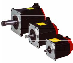
αi series
- 3 -

2.ORDERING SPECIFICATION NUMBER |
B-65262EN/06 |
2 ORDERING SPECIFICATION NUMBER
This chapter provides information about the ordering specification numbers and types of the FANUC AC Servo Motor αi series.
Chapter 2, "ORDERING SPECIFICATION NUMBER", consists of the following sections:
2.1 |
ORDERING SPECIFICATION NUMBER.......................................................................................... |
4 |
2.2 |
APPLICABLE AMPLIFIERS .............................................................................................................. |
8 |
2.1 ORDERING SPECIFICATION NUMBER
The ordering specification numbers of the servo motors have the following format:
A06B-□□□□-B○#
□□□□
An ordering specification number are described on the tables after next page.
*Every combination doesn’t exist.
0: Taper shaft
1: Straight shaft
2: Straight shaft with a key groove
3: Taper shaft with a 24VDC brake
4: Straight shaft with a 24VDC brake
5: Straight shaft with a key way and a 24VDC brake
*Do not select "Straight shaft with a key groove" when a large torque or abrupt acceleration rate is required.
○
0 : Standard
1: With a fan
2: With a high-torque brake
3: With a high-torque brake and a fan
4: With a strong fan
5: With a fan
* When "With a high-torque brake" is selected (○ = 2 or 3), specify = 3 to 5.
|
|
|
0 |
: |
Pulsecoder αiA 1000 |
1 |
: |
Pulsecoder αiI 1000 |
2 |
: |
Pulsecoder αiA 16000 |
|
|
|
0000 |
: |
Standard |
0100 |
: |
IP67 specification |
- 4 -
B-65262EN/06 |
2.ORDERING SPECIFICATION NUMBER |
*Omitted in case of #0000.
The following table lists the allowable combinations of numbers represented by symbols in ordering specification numbers.
αiS series (200V)
A06B-□□□□-B○#
Symbol in specification No.
Servo motor name
αiS 2/5000
αiS 2/6000
αiS 4/5000
αiS 4/6000
αiS 8/4000
αiS 8/6000
αiS 12/4000
αiS 12/6000
αiS 22/4000
αiS 22/6000
αiS 30/4000
αiS 40/4000
αiS 50/2000
αiS 60/2000
αiS 50/3000 with fan
αiS 60/3000 with fan
αiS 100/2500
αiS 100/2500 with fan
αiS 200/2500
αiS 200/2500 with fan
αiS 300/2000
αiS 500/2000
|
|
|
|
|
|
|
|
|
|
○ |
|
|
|
|
|
|
|||
□□□□ |
|
|
|
|
|
|
|
|
|
|
|
|
|
|
|
|
|
|
|
0 |
1 |
2 |
|
3 |
4 |
5 |
0 |
1 |
2 |
|
3 |
4 |
5 |
0 |
1 |
2 |
0000 |
0100 |
|
|
|
|
|
|
|
|
|
|
|
|
|
|
|
|
|
|
|
||
0212 |
○ |
○ |
○ |
○ |
○ |
○ |
○ |
|
|
|
|
|
○ |
○ |
○ |
○ |
○ |
||
0218 |
○ |
○ |
○ |
○ |
○ |
○ |
○ |
|
|
|
|
|
○ |
○ |
○ |
○ |
○ |
||
0215 |
○ |
○ |
○ |
○ |
○ |
○ |
○ |
|
|
|
|
|
○ |
○ |
○ |
○ |
○ |
||
0210 |
○ |
○ |
○ |
○ |
○ |
○ |
○ |
|
|
|
|
|
○ |
○ |
○ |
○ |
○ |
||
0235 |
○ |
○ |
○ |
○ |
○ |
○ |
○ |
|
|
|
|
|
○ |
○ |
○ |
○ |
○ |
||
0232 |
○ |
○ |
○ |
○ |
○ |
○ |
○ |
|
|
|
|
|
○ |
○ |
○ |
○ |
○ |
||
0238 |
○ |
○ |
○ |
○ |
○ |
○ |
○ |
|
|
|
|
|
○ |
○ |
○ |
○ |
○ |
||
0230 |
○ |
○ |
○ |
○ |
○ |
○ |
○ |
|
|
|
|
|
○ |
○ |
○ |
○ |
○ |
||
0265 |
○ |
○ |
○ |
○ |
○ |
○ |
○ |
|
|
|
|
|
○ |
○ |
○ |
○ |
○ |
||
0262 |
○ |
○ |
○ |
○ |
○ |
○ |
○ |
|
|
|
|
|
○ |
○ |
○ |
○ |
○ |
||
0268 |
○ |
○ |
○ |
○ |
○ |
○ |
○ |
|
|
|
|
|
○ |
○ |
○ |
○ |
○ |
||
0272 |
○ |
○ |
○ |
○ |
○ |
○ |
○ |
|
|
|
|
|
○ |
○ |
○ |
○ |
○ |
||
|
|
|
|
|
|
|
|
|
|
|
|
|
|
|
|
|
|||
|
|
|
○ |
○ |
○ |
|
|
○ |
|
|
|
○ |
○ |
○ |
○ |
○ |
|||
0042 |
○ |
○ |
|
|
|
|
○ |
|
|
|
|
|
○ |
○ |
○ |
○ |
○ |
||
|
|
|
|
|
|
|
|
|
|
|
|
|
|
|
|
|
|||
|
|
|
○ |
○ |
|
|
|
○ |
|
|
|
○ |
○ |
○ |
○ |
○ |
|||
|
|
|
|
|
|
|
|
|
|
|
|
|
|
|
|
|
|
||
0044 |
○ |
○ |
|
|
|
|
○ |
|
|
|
|
|
○ |
○ |
○ |
○ |
○ |
||
|
|
|
|
|
|
|
|
|
|
|
|
|
|
|
|
|
|||
|
|
|
○ |
○ |
|
|
|
○ |
|
|
|
○ |
○ |
○ |
○ |
○ |
|||
|
|
|
|
|
|
|
|
|
|
|
|
|
|
|
|
|
|
||
0275 |
○ |
○ |
|
○ |
○ |
|
|
○ |
|
|
|
|
○ |
○ |
○ |
○ |
|
||
|
|
|
|
|
|
|
|
|
|
|
|
|
|
|
|
|
|||
|
|
|
○ |
○ |
|
|
|
|
○ |
|
|
○ |
○ |
○ |
○ |
|
|||
|
|
|
|
|
|
|
|
|
|
|
|
|
|
|
|
|
|
||
0278 |
○ |
○ |
|
|
|
|
|
○ |
|
|
|
|
○ |
○ |
○ |
○ |
|
||
|
|
|
|
|
|
|
|
|
|
|
|
|
|
|
|
|
|||
|
|
|
○ |
○ |
|
|
|
|
○ |
|
|
○ |
○ |
○ |
○ |
|
|||
|
|
|
|
|
|
|
|
|
|
|
|
|
|
|
|
|
|
||
0285 |
○ |
|
|
○ |
|
|
○ |
|
|
|
|
|
○ |
|
|
○ |
○ |
||
0285 |
○ |
|
|
○ |
|
|
|
○ |
|
|
|
|
○ |
|
|
○ |
|
||
0288 |
○ |
|
|
○ |
|
|
○ |
|
|
|
|
|
○ |
|
|
○ |
○ |
||
0288 |
○ |
|
|
○ |
|
|
|
○ |
|
|
|
|
○ |
|
|
○ |
|
||
0292 |
○ |
|
|
|
|
|
|
○ |
|
|
|
|
○ |
|
|
○ |
|
||
0295 |
○ |
|
|
|
|
|
|
○ |
|
|
|
|
○ |
|
|
○ |
|
||
|
|
|
|
|
|
|
|
|
|
|
|
|
|
|
|
|
|
|
|
* |
When is #0000, omit the specification of . |
* |
Specify = 3 to 5 in the case of ○ = 2 or 3. |
- 5 -
2.ORDERING SPECIFICATION NUMBER |
B-65262EN/06 |
αiS series (400V)
A06B-□□□□-B○#
Symbol in specification No.
Servo motor name
αiS 2/5000 HV
αiS 2/6000 HV
αiS 4/5000 HV
αiS 4/6000 HV
αiS 8/4000 HV
αiS 8/6000 HV
αiS 12/4000 HV
αiS 12/6000 HV
αiS 22/4000 HV
αiS 22/6000 HV
αiS 30/4000 HV
αiS 40/4000 HV
αiS 50/2000 HV
αiS 60/2000 HV
αiS 50/3000 HV with fan
αiS 60/3000 HV with fan
αiS 100/2500 HV
αiS 100/2500 HV with fan
αiS 200/2500 HV
αiS 200/2500 HV with fan
αiS 300/2000 HV
αiS 300/3000 HV
αiS 500/2000 HV
αiS 500/3000 HV
αiS 1000/2000 HV
αiS 1000/3000 HV
αiS 2000/2000 HV
αiS 3000/2000 HV
|
|
|
|
|
|
|
|
|
|
○ |
|
|
|
|
|
|
||||
□□□□ |
|
|
|
|
|
|
|
|
|
|
|
|
|
|
|
|
|
|
|
|
0 |
1 |
2 |
|
3 |
4 |
5 |
0 |
1 |
2 |
|
3 |
4 |
5 |
0 |
1 |
2 |
0000 |
0100 |
||
|
|
|
||||||||||||||||||
|
|
|
|
|
|
|
|
|
|
|
|
|
|
|
|
|
|
|||
0213 |
○ |
○ |
○ |
○ |
○ |
○ |
○ |
|
|
|
|
|
○ |
○ |
○ |
○ |
○ |
|||
0219 |
○ |
○ |
○ |
○ |
○ |
○ |
○ |
|
|
|
|
|
○ |
○ |
○ |
○ |
○ |
|||
0216 |
○ |
○ |
○ |
○ |
○ |
○ |
○ |
|
|
|
|
|
○ |
○ |
○ |
○ |
○ |
|||
0214 |
○ |
○ |
○ |
○ |
○ |
○ |
○ |
|
|
|
|
|
○ |
○ |
○ |
○ |
○ |
|||
0236 |
○ |
○ |
○ |
○ |
○ |
○ |
○ |
|
|
|
|
|
○ |
○ |
○ |
○ |
○ |
|||
0233 |
○ |
○ |
○ |
○ |
○ |
○ |
○ |
|
|
|
|
|
○ |
○ |
○ |
○ |
○ |
|||
0239 |
○ |
○ |
○ |
○ |
○ |
○ |
○ |
|
|
|
|
|
○ |
○ |
○ |
○ |
○ |
|||
0237 |
○ |
○ |
○ |
○ |
○ |
○ |
○ |
|
|
|
|
|
○ |
○ |
○ |
○ |
○ |
|||
0266 |
○ |
○ |
○ |
○ |
○ |
○ |
○ |
|
|
|
|
|
○ |
○ |
○ |
○ |
○ |
|||
0263 |
○ |
○ |
○ |
○ |
○ |
○ |
○ |
|
|
|
|
|
○ |
○ |
○ |
○ |
○ |
|||
0269 |
○ |
○ |
○ |
○ |
○ |
○ |
○ |
|
|
|
|
|
○ |
○ |
○ |
○ |
○ |
|||
0273 |
○ |
○ |
○ |
○ |
○ |
○ |
○ |
|
|
|
|
|
○ |
○ |
○ |
○ |
○ |
|||
|
|
|
|
|
|
|
|
|
|
|
|
|
|
|
|
|
|
|
||
|
|
|
○ |
○ |
○ |
|
|
○ |
|
|
|
○ |
○ |
○ |
○ |
○ |
||||
|
||||||||||||||||||||
|
|
|
|
|
|
|
|
|
|
|
|
|
|
|
|
|
|
|||
0043 |
○ |
○ |
|
|
|
|
○ |
|
|
|
|
|
○ |
○ |
○ |
○ |
○ |
|||
|
|
|
|
|
|
|
|
|
|
|
|
|
|
|
|
|
|
|
||
|
|
|
○ |
○ |
|
|
|
○ |
|
|
|
○ |
○ |
○ |
○ |
○ |
||||
|
||||||||||||||||||||
|
|
|
|
|
|
|
|
|
|
|
|
|
|
|
|
|
|
|||
0045 |
○ |
○ |
|
|
|
|
○ |
|
|
|
|
|
○ |
○ |
○ |
○ |
○ |
|||
|
|
|
|
|
|
|
|
|
|
|
|
|
|
|
|
|
|
|
||
|
|
|
○ |
○ |
|
|
|
○ |
|
|
|
○ |
○ |
○ |
○ |
○ |
||||
|
||||||||||||||||||||
|
|
|
|
|
|
|
|
|
|
|
|
|
|
|
|
|
|
|||
0276 |
○ |
○ |
|
○ |
○ |
|
|
○ |
|
|
|
|
○ |
○ |
○ |
○ |
|
|||
|
|
|
|
|
|
|
|
|
|
|
|
|
|
|
|
|
|
|
||
|
|
|
○ |
○ |
|
|
|
|
○ |
|
|
○ |
○ |
○ |
○ |
|
||||
|
||||||||||||||||||||
0279 |
○ |
○ |
|
|
|
|
|
○ |
|
|
|
|
○ |
○ |
○ |
○ |
|
|||
|
|
|
|
|
|
|
|
|
|
|
|
|
|
|
|
|
|
|
||
|
|
|
○ |
○ |
|
|
|
|
○ |
|
|
○ |
○ |
○ |
○ |
|
||||
|
||||||||||||||||||||
|
|
|
|
|
|
|
|
|
|
|
|
|
|
|
|
|
|
|||
0286 |
○ |
|
|
○ |
|
|
○ |
|
|
|
|
|
○ |
|
|
○ |
○ |
|||
0286 |
○ |
|
|
○ |
|
|
|
○ |
|
|
|
|
○ |
|
|
○ |
|
|||
0289 |
○ |
|
|
○ |
|
|
○ |
|
|
|
|
|
○ |
|
|
○ |
○ |
|||
0289 |
○ |
|
|
○ |
|
|
|
○ |
|
|
|
|
○ |
|
|
○ |
|
|||
0293 |
○ |
|
|
|
|
|
|
○ |
|
|
|
|
○ |
|
|
○ |
|
|||
0290 |
○ |
|
|
|
|
|
|
○ |
|
|
|
|
○ |
|
|
○ |
|
|||
0296 |
○ |
|
|
|
|
|
|
○ |
|
|
|
|
○ |
|
|
○ |
|
|||
0297 |
○ |
|
|
|
|
|
|
○ |
|
|
|
|
○ |
|
|
○ |
|
|||
0098 |
○ |
|
|
|
|
|
|
○ |
|
|
|
|
○ |
|
|
○ |
|
|||
0099 |
○ |
|
|
|
|
|
|
|
|
|
|
○ |
○ |
|
|
○ |
|
|||
0091 |
○ |
|
|
|
|
|
|
|
|
|
○ |
|
○ |
|
|
○ |
|
|||
0092 |
○ |
|
|
|
|
|
|
|
|
|
○ |
|
○ |
|
|
○ |
|
|||
|
|
|
|
|
|
|
|
|
|
|
|
|
|
|
|
|
|
|
|
|
* |
When is #0000, omit the specification of . |
* |
Specify = 3 to 5 in the case of ○ = 2 or 3. |
- 6 -

B-65262EN/06 |
|
|
|
|
|
|
2.ORDERING SPECIFICATION NUMBER |
||||||||||||
αiF series (200V) |
|
|
|
|
|
|
|
|
|
|
|
|
|
|
|
|
|
|
|
A06B-□□□□-B○# |
|
|
|
|
|
|
|
|
|
|
|
|
|
|
|
|
|||
|
Symbol in |
|
|
|
|
|
|
|
|
|
○ |
|
|
|
|
|
|
|
|
|
specification |
□□□□ |
|
|
|
|
|
|
|
|
|
|
|
|
|
|
|
|
|
|
No. |
0 |
1 |
2 |
3 |
4 |
5 |
0 |
1 |
2 |
3 |
4 |
5 |
0 |
1 |
2 |
0000 |
0100 |
|
|
|
||||||||||||||||||
Servo motor name |
|
|
|
|
|
|
|
|
|
|
|
|
|
|
|
|
|
|
|
|
αiF 1/5000 |
0202 |
○ ○ ○ ○ ○ ○ ○ ○ ○ ○ |
○ |
○ |
||||||||||||||
|
αiF 2/5000 |
0205 |
○ ○ ○ ○ ○ ○ ○ ○ ○ ○ |
○ |
○ |
||||||||||||||
|
αiF 4/4000 |
0223 |
○ ○ ○ ○ ○ ○ ○ ○ ○ ○ |
○ |
○ |
||||||||||||||
|
αiF 8/3000 |
0227 |
○ ○ ○ ○ ○ ○ ○ ○ ○ ○ |
○ |
○ |
||||||||||||||
|
αiF 12/3000 |
0243 |
○ ○ ○ ○ ○ ○ ○ ○ ○ ○ |
○ |
○ |
||||||||||||||
|
αiF 22/3000 |
0247 |
○ ○ ○ ○ ○ ○ ○ ○ ○ ○ |
○ |
○ |
||||||||||||||
|
αiF 30/3000 |
0253 |
○ ○ ○ ○ ○ ○ ○ ○ ○ ○ |
○ |
○ |
||||||||||||||
|
αiF 40/3000 |
0257 |
○ ○ ○ ○ ○ ○ ○ ○ ○ ○ ○ ○ |
||||||||||||||||
|
○ ○ ○ ○ ○ ○ ○ ○ ○ |
||||||||||||||||||
|
|
|
|||||||||||||||||
|
αiF 40/3000 with fan |
0257 |
○ ○ ○ ○ ○ ○ ○ ○ ○ ○ ○ |
||||||||||||||||
|
○ ○ ○ ○ ○ ○ ○ ○ |
||||||||||||||||||
|
|
|
|||||||||||||||||
* |
When is #0000, omit the specification of . |
|
|
|
|
|
|
|
|
||||||||||
* |
Specify = 3 to 5 in the case of ○ = 2 or 3. |
|
|
|
|
|
|
|
|
|
|
|
|
||||||
αiF series (400V)
A06B-□□□□-B○#
Symbol in specification No.
Servo motor name
αiF 4/4000 HV
αiF 8/3000 HV
αiF 12/3000 HV
αiF 22/3000 HV
|
|
|
|
|
|
|
|
|
|
○ |
|
|
|
|
|
|
|||
□□□□ |
|
|
|
|
|
|
|
|
|
|
|
|
|
|
|
|
|
|
|
0 |
1 |
2 |
|
3 |
4 |
5 |
0 |
1 |
2 |
|
3 |
4 |
5 |
0 |
1 |
2 |
0000 |
0100 |
|
|
|
|
|||||||||||||||||
|
|
|
|
|
|
|
|
|
|
|
|
|
|
|
|
|
|
||
0225 |
○ |
○ |
○ |
○ |
○ |
○ |
○ |
|
|
|
|
|
○ |
○ |
○ |
○ |
○ |
||
0229 |
○ |
○ |
○ |
○ |
○ |
○ |
○ |
|
|
|
|
|
○ |
○ |
○ |
○ |
○ |
||
0245 |
○ |
○ |
○ |
○ |
○ |
○ |
○ |
|
|
|
|
|
○ |
○ |
○ |
○ |
○ |
||
0249 |
○ |
○ |
○ |
○ |
○ |
○ |
○ |
|
|
|
|
|
○ |
○ |
○ |
○ |
○ |
||
|
|
|
|
|
|
|
|
|
|
|
|
|
|
|
|
|
|
|
|
* When is #0000, omit the specification of .
- 7 -
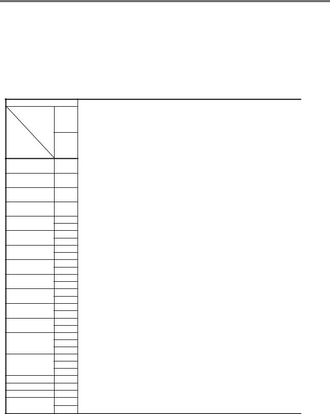
2.ORDERING SPECIFICATION NUMBER |
B-65262EN/06 |
2.2 APPLICABLE AMPLIFIERS
The FANUC AC Servo Motor αi series can be driven using FANUC Servo Amplifier αiSV series or βiSV series.
For the ordering specification numbers of servo amplifiers, refer to "FANUC SERVO AMPLIFIER αi series Descriptions (B-65282EN)" or "FANUC SERVO AMPLIFIER βi series Descriptions (B-65322EN)".
Combinations of αiS/αiF servo motors and αiSV/βiSV servo amplifiers
(200 V, 160 A or less)
Stall torque
Motor |
αiS |
|
|
||
Amplifier |
αiF |
|
|
||
αiSV 20 |
- |
|
αiSV 20L |
||
|
||
αiSV 40 |
- |
|
αiSV 40L |
||
|
||
αiSV 80 |
- |
|
αiSV 80L |
||
|
||
αiSV 160 |
- |
|
αiSV 160L |
||
|
||
αiSV 4/20 |
L axis |
|
M axis |
||
|
||
αiSV 20/20 |
L axis |
|
αiSV 20/20L |
M axis |
|
αiSV 20/40 |
L axis |
|
αiSV 20/40L |
M axis |
|
αiSV 40/40 |
L axis |
|
αiSV 40/40L |
M axis |
|
αiSV 40/80 |
L axis |
|
αiSV 40/80L |
M axis |
|
αiSV 80/80 |
L axis |
|
αiSV 80/80L |
M axis |
|
αiSV 80/160 |
L axis |
|
M axis |
||
|
||
αiSV 160/160 |
L axis |
|
M axis |
||
|
||
αiSV 20/20/20 |
L axis |
|
M axis |
||
|
N axis |
|
αiSV 20/20/40 |
L axis |
|
M axis |
||
|
N axis |
|
βiSV 20 |
- |
|
βiSV 40 |
- |
|
βiSV 80 |
- |
|
βiSV 20/20 |
L axis |
|
M axis |
||
|
1 |
|
2 |
|
4 |
|
8 |
|
12 |
|
|||
|
αiS 2 |
|
αiS 2 |
αiS 4 |
αiS 4 |
|
|
αiS 8 |
αiS 8 |
αiS12 |
αiS12 |
|
|
/5000 |
|
/6000 |
/5000 |
/6000 |
|
|
/4000 |
/6000 |
/4000 |
|
/6000 |
|
|
|
|
|
|
|
|
|
|
|
|
|
αiF 1 |
αiF 2 |
|
|
|
|
αiF 4 |
αiF 8 |
|
|
αiF12 |
|
|
/5000 |
/5000 |
|
|
|
|
/4000 |
/3000 |
|
|
/3000 |
|
|
|
|
|
|
|
|
|
|
|
|
|
|
|
O |
O |
|
O |
O |
O |
|
|
|
|
|
|
|
|
|
|
|
|
|
|
|
|
|
|
|
|
|
|
|
|
|
|
O |
O |
|
|
|
|
|
|
|
|
|
|
|
|
|
|
|
|
|
|
|
|
|
|
|
|
|
|
O |
O |
O |
|
|
|
|
|
|
|
|
|
|
|
|
|
|
|
|
|
|
|
|
|
|
|
|
|
|
|
O |
|
|
|
|
|
|
|
|
|
|
|
|
|
|
|
|
|
|
|
|
|
|
|
|
|
|
O |
O |
|
O |
O |
O |
|
|
|
|
|
|
|
O |
O |
|
O |
O |
O |
|
|
|
|
|
|
|
O |
O |
|
O |
O |
O |
|
|
|
|
|
|
|
O |
O |
|
O |
O |
O |
|
|
|
|
|
|
|
|
|
|
|
|
|
O |
O |
|
|
|
|
|
|
|
|
|
|
|
O |
O |
|
|
|
|
|
|
|
|
|
|
|
O |
O |
|
|
|
|
|
|
|
|
|
|
|
O |
O |
|
|
|
|
|
|
|
|
|
|
|
|
|
O |
O |
O |
|
|
|
|
|
|
|
|
|
|
O |
O |
O |
|
|
|
|
|
|
|
|
|
|
O |
O |
O |
|
|
|
|
|
|
|
|
|
|
O |
O |
O |
|
|
|
|
|
|
|
|
|
|
|
|
|
|
O |
|
|
|
|
|
|
|
|
|
|
|
|
O |
|
|
|
|
|
|
|
|
|
|
|
|
O |
O |
O |
|
O |
O |
O |
|
|
|
|
|
|
|
O |
O |
|
O |
O |
O |
|
|
|
|
|
|
|
O |
O |
|
O |
O |
O |
|
|
|
|
|
|
|
O |
O |
|
O |
O |
O |
|
|
|
|
|
|
|
O |
O |
|
O |
O |
O |
|
|
|
|
|
|
|
|
|
|
|
|
|
O |
O |
|
|
|
|
|
O |
O |
|
O |
O |
O |
|
|
|
|
|
|
|
|
|
|
|
|
|
O |
O |
|
|
|
|
|
|
|
|
|
|
|
|
|
O |
O |
O |
|
|
O |
O |
|
O |
O |
O |
|
|
|
|
|
|
|
O |
O |
|
O |
O |
O |
|
|
|
|
|
|
|
|
|
|
|
|
|
|
|
|
|
|
|
|
- 8 -

B-65262EN/06 |
2.ORDERING SPECIFICATION NUMBER |
Stall torque
Motor |
αiS |
|
|
||
Amplifier |
αiF |
|
|
||
αiSV 20 |
- |
|
αiSV 20L |
||
|
||
αiSV 40 |
- |
|
αiSV 40L |
||
|
||
αiSV 80 |
- |
|
αiSV 80L |
||
|
||
αiSV 160 |
- |
|
αiSV 160L |
||
L axis |
||
αiSV 4/20 |
||
M axis |
||
|
||
αiSV 20/20 |
L axis |
|
αiSV 20/20L |
M axis |
|
αiSV 20/40 |
L axis |
|
αiSV 20/40L |
M axis |
|
αiSV 40/40 |
L axis |
|
αiSV 40/40L |
M axis |
|
αiSV 40/80 |
L axis |
|
αiSV 40/80L |
M axis |
|
αiSV 80/80 |
L axis |
|
αiSV 80/80L |
M axis |
|
αiSV 80/160 |
L axis |
|
M axis |
||
|
||
αiSV 160/160 |
L axis |
|
M axis |
||
|
||
αiSV 20/20/20 |
L axis |
|
M axis |
||
|
N axis |
|
αiSV 20/20/40 |
L axis |
|
M axis |
||
βiSV 20 |
N axis |
|
- |
||
βiSV 40 |
- |
|
βiSV 80 |
- |
|
βiSV 20/20 |
L axis |
|
M axis |
||
|
22 |
|
30 |
40 |
50 |
60 |
||
|
αiS22 |
αiS22 |
αiS30 |
αiS40 |
|
αiS50 |
αiS60 |
|
/4000 |
/6000 |
/4000 |
/4000 |
|
/2000 |
/2000 |
|
|
|
|
|
|
|
|
αiF22 |
|
|
αiF30 |
αiF40 |
αiF40 |
|
|
/3000 |
|
|
/3000 |
/3000 |
/3000 |
|
|
|
|
FAN |
|
|
|||
|
|
|
|
|
|
|
|
|
|
|
|
|
|
|
|
|
|
|
|
|
|
|
|
O |
|
|
|
|
|
|
|
|
|
|
|
|
|
|
|
|
O |
O |
O |
O |
O |
O |
O |
|
|
|
|
|
|
|
|
|
|
|
|
|
|
|
|
|
|
|
|
|
|
|
|
|
|
|
|
|
|
|
|
|
|
|
|
|
|
|
|
|
|
|
|
|
|
|
|
|
|
|
|
|
|
|
|
|
|
|
|
|
|
|
|
|
|
|
|
|
|
|
|
|
|
|
|
|
|
|
|
O |
|
|
|
|
|
|
|
O |
|
|
|
|
|
|
|
O |
|
|
|
|
|
|
|
O |
|
|
|
|
|
|
|
|
O |
O |
O |
O |
|
O |
O |
|
O |
O |
O |
O |
|
O |
O |
|
O |
O |
O |
O |
|
O |
O |
|
|
|
|
|
|
|
|
|
|
|
|
|
|
|
|
|
|
|
|
|
|
|
|
|
|
|
|
|
|
|
|
|
|
|
|
|
|
|
|
|
|
|
|
|
|
|
|
|
|
|
|
|
|
|
|
|
|
|
|
|
|
|
|
O |
|
|
|
|
|
|
|
|
|
|
|
|
|
|
|
|
|
|
|
|
|
|
|
(200 V, 360 A or more)
Stall torque |
50 |
60 |
|
100 |
200 |
|
300 |
500 |
||
Motor |
αiS 50 |
αiS 60 |
αiS 100 |
αiS 100 |
αiS 200 |
αiS 200 |
αiS 300 |
αiS 500 |
||
Amplifier |
/3000 |
/3000 |
/2500 |
|
/2500 |
/2500 |
|
/2500 |
/2000 |
/2000 |
FAN |
FAN |
|
|
FAN |
|
|
FAN |
|
|
|
αiSV 360 |
O |
O |
O |
|
O |
O |
|
O |
|
|
αiSV 360 x2 |
|
|
|
|
|
|
|
|
O |
O |
(*)For a motor driven by multiple servo amplifier, such as the αiS 300 motor, the torque tandem control option or the PWM distribution module is required.
- 9 -
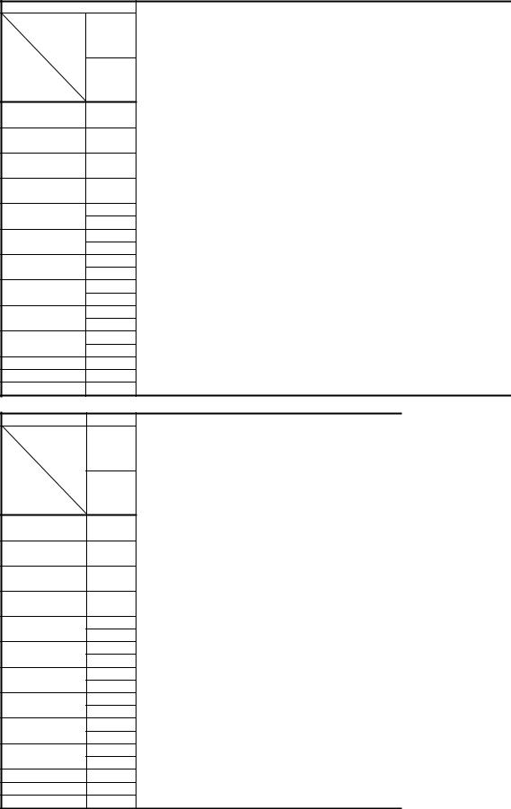
2.ORDERING SPECIFICATION NUMBER |
B-65262EN/06 |
(400V, 80A or less)
Stall torque
Motor |
αiS |
|
|
||
Amplifier |
αiF |
|
|
||
αiSV 10HV |
- |
|
αiSV 10HVL |
||
|
||
αiSV 20HV |
- |
|
αiSV 20HVL |
||
|
||
αiSV 40HV |
- |
|
αiSV 40HVL |
||
|
||
αiSV 80HV |
- |
|
αiSV 80HV |
||
|
||
αiSV 10/10HV |
L axis |
|
αiSV 10/10HVL |
M axis |
|
αiSV 20/20HV |
L axis |
|
αiSV 20/20HVL |
M axis |
|
αiSV 20/40HV |
L axis |
|
αiSV 20/40HVL |
M axis |
|
αiSV 40/40HV |
L axis |
|
αiSV 40/40HVL |
M axis |
|
αiSV 40/80HV |
L axis |
|
M axis |
||
|
||
αiSV 80/80HV |
L axis |
|
M axis |
||
|
||
βiSV 10HV |
- |
|
βiSV 20HV |
- |
|
βiSV 40HV |
- |
|
2 |
|
4 |
|
8 |
|
12 |
|
|||
αiS 2 |
|
αiS 2 |
αiS 4 |
αiS 4 |
|
|
αiS 8 |
αiS 8 |
αiS12 |
αiS12 |
|
/5000 |
|
/6000 |
/5000 |
/6000 |
|
|
/4000 |
/6000 |
/4000 |
|
/6000 |
HV |
|
HV |
HV |
HV |
|
|
HV |
HV |
HV |
|
HV |
|
|
|
|
|
αiF 4 |
αiF 8 |
|
|
αiF12 |
|
|
|
|
|
|
|
/4000 |
/3000 |
|
|
/3000 |
|
|
|
|
|
|
|
HV |
HV |
|
|
HV |
|
|
O |
|
O |
O |
O |
|
|
|
|
|
|
|
|
|
|
|
|
|
|
|
|
|
|
|
|
|
|
|
|
O |
O |
|
|
|
|
|
|
|
|
|
|
|
|
|
|
|
|
|
|
|
|
|
|
|
|
O |
O |
O |
|
|
|
|
|
|
|
|
|
|
|
|
|
|
|
|
|
|
|
|
|
|
|
|
|
O |
|
|
|
|
|
|
|
|
|
|
|
|
O |
|
O |
O |
O |
|
|
|
|
|
|
|
O |
|
O |
O |
O |
|
|
|
|
|
|
|
|
|
|
|
|
O |
O |
|
|
|
|
|
|
|
|
|
|
O |
O |
|
|
|
|
|
|
|
|
|
|
O |
O |
|
|
|
|
|
|
|
|
|
|
|
|
O |
O |
O |
|
|
|
|
|
|
|
|
|
O |
O |
O |
|
|
|
|
|
|
|
|
|
O |
O |
O |
|
|
|
|
|
|
|
|
|
O |
O |
O |
|
|
|
|
|
|
|
|
|
|
|
|
|
O |
|
|
|
|
|
|
|
|
|
|
|
O |
|
|
|
|
|
|
|
|
|
|
|
O |
O |
|
O |
O |
O |
|
|
|
|
|
|
|
|
|
|
|
|
O |
O |
|
|
|
|
|
|
|
|
|
|
|
|
O |
O |
O |
|
|
Stall torque
Motor |
αiS |
|
|
||
Amplifier |
αiF |
|
|
||
αiSV 10HV |
- |
|
αiSV 10HVL |
||
|
||
αiSV 20HV |
- |
|
αiSV 20HVL |
||
|
||
αiSV 40HV |
- |
|
αiSV 40HVL |
||
|
||
αiSV 80HV |
- |
|
αiSV 80HV |
||
|
||
αiSV 10/10HV |
L axis |
|
αiSV 10/10HVL |
M axis |
|
αiSV 20/20HV |
L axis |
|
αiSV 20/20HVL |
M axis |
|
αiSV 20/40HV |
L axis |
|
αiSV 20/40HVL |
M axis |
|
αiSV 40/40HV |
L axis |
|
αiSV 40/40HVL |
M axis |
|
αiSV 40/80HV |
L axis |
|
M axis |
||
|
||
αiSV 80/80HV |
L axis |
|
M axis |
||
|
||
βiSV 10HV |
- |
|
βiSV 20HV |
- |
|
βiSV 40HV |
- |
22 |
|
30 |
40 |
50 |
60 |
|
|
αiS22 |
αiS22 |
αiS30 |
αiS40 |
αiS50 |
αiS60 |
|
/4000 |
/6000 |
/4000 |
/4000 |
/2000 |
/2000 |
|
HV |
HV |
HV |
HV |
HV |
HV |
αiF22 |
|
|
|
|
|
|
/3000 |
|
|
|
|
|
|
HV |
|
|
|
|
|
|
|
|
|
|
|
|
|
|
|
|
|
|
|
|
O |
|
|
|
|
|
|
|
|
|
|
|
|
|
|
O |
O |
O |
O |
O |
O |
|
|
|
|
|
|
|
|
|
|
|
|
|
|
|
|
|
|
|
|
|
|
|
|
|
|
|
|
|
|
|
|
|
|
|
|
|
|
|
|
|
|
O |
|
|
|
|
|
|
O |
|
|
|
|
|
|
O |
|
|
|
|
|
|
O |
|
|
|
|
|
|
|
O |
O |
O |
O |
O |
O |
|
O |
O |
O |
O |
O |
O |
|
O |
O |
O |
O |
O |
O |
|
|
|
|
|
|
|
|
|
|
|
|
|
|
O |
|
|
|
|
|
|
|
|
|
|
|
|
|
- 10 -
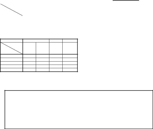
B-65262EN/06 |
|
|
|
|
|
|
|
2.ORDERING SPECIFICATION NUMBER |
||||||
(400V, 180A or more) |
|
|
|
|
|
|
|
|
|
500 |
|
|||
tall torque |
50 |
60 |
|
100 |
|
200 |
|
300 |
|
|||||
Motor |
αiS 50 |
αiS 60 |
αiS 100 |
αiS 100 |
αiS 200 |
αiS 200 |
αiS 300 |
αiS 300 |
αiS 500 |
αiS 500 |
|
|||
Amplifier |
/3000 |
/3000 |
/2500 |
|
/2500 |
/2500 |
|
/2500 |
/2000 |
|
/3000 |
/2000 |
/3000 |
|
HV FAN |
HV FAN |
HV |
|
HV FAN |
HV |
|
HV FAN |
HV |
|
HV |
HV |
HV |
|
|
αiSV 180HV |
O |
O |
O |
|
O |
O |
|
O |
|
|
|
|
|
|
αiSV 360HV |
|
|
|
|
|
|
|
|
O |
|
|
O |
|
|
αiSV 360HV x2 |
|
|
|
|
|
|
|
|
|
|
|
|
|
|
αiSV 360HV x4 |
|
|
|
|
|
|
|
|
|
|
|
|
|
|
αiSV 540HV |
|
|
|
|
|
|
|
|
|
|
O |
|
O |
|
tall torque |
1000 |
2000 |
3000 |
|
Motor αiS 1000 |
αiS 1000 |
αiS 2000 |
αiS 3000 |
|
Amplifier |
/2000 |
/3000 |
/2000 |
/2000 |
HV |
HV |
HV |
HV |
|
αiSV 180HV |
|
|
|
|
αiSV 360HV |
|
|
|
|
αiSV 360HV x2 |
O |
|
|
|
αiSV 360HV x4 |
|
O |
O |
O |
αiSV 540HV |
|
|
|
|
(*)For a motor driven by multiple servo amplifier, such as the αiS 1000HV motor, the torque tandem control option or the PWM distribution module is required.
 CAUTION
1If a motor is used in a combination other than those listed above, it may become broken.
2For details on the servo amplifier, refer to "FANUC SERVO AMPLIFIER αi series DESCRIPTIONS (B-65282EN)" and “FANUC SERVO AMPLIFIER βi series DESCRIPTIONS (B-65322EN)”.
3If you want to use a motor in combination with the α/β series servo amplifier, consult with FANUC.
- 11 -
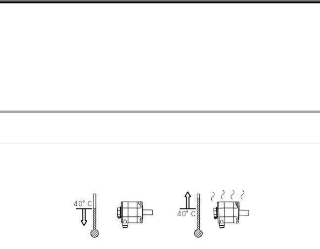
3.USAGE |
B-65262EN/06 |
3 USAGE
This chapter explains how to connect the FANUC AC Servo Motor αi series to the CNC system and how to install it in the machine.
Chapter 3, "USAGE", consists of the following sections:
3.1 |
USE ENVIRONMENT FOR SERVO MOTORS............................................................................... |
12 |
3.2 |
CONNECTING A SERVO MOTOR ................................................................................................. |
19 |
3.3 |
MOUNTING A SERVO MOTOR...................................................................................................... |
21 |
3.1 USE ENVIRONMENT FOR SERVO MOTORS
3.1.1 Ambient Temperature, Humidity, Installation Height, and
Vibration
Ambient temperature
The ambient temperature should be 0°C to 40°C. If the ambient temperature exceeds this range, the operating conditions must be eased to prevent the motor and detector from overheating. (The values in the data sheet are determined for an ambient temperature of 20°C.)
Ambient humidity
The ambient humidity should be 80%RH or less and no condensation should not be caused.
Installation height
Up to 1,000 meters above the sea level requires, no particular provision for attitude. When operating the machine at a higher level, special care is unnecessary if the ambient temperature is lowered 1°C at every 100m higher than 1,000m. For example, when the machine is installed at a place of 1,500 meters above sea level, there is no problem if the ambient temperature is 35°C or less.
Vibration
When installed in a machine, the vibration applied to the motor must not exceed 5G.
If any one of the four environmental conditions (ambient temperature, ambient humidity, installation height, and vibration) specified above is not satisfied, the output must be restricted.
- 12 -

B-65262EN/06 |
3.USAGE |
3.1.2 Usage Considering Environmental Resistance
Overview
The motor is an electric part, and if the lubricant or cutting fluid falls on the motor, it will enter the inside of the motor, possibly adversely affecting the motor. In particular, if the cutting fluid adheres to the motor, it will deteriorate the resin or rubber sealing members, causing a large amount of cutting fluid to enter the inside of the motor and possibly damaging the motor. When using the motor, note the points described below.
Level of motor protection
For the standard type, the level of motor protection is such that a single motor unit can satisfy IP65 of the IEC 60034-5 standard, and a single motor unit of αiS 2000/2000HV and above can satisfy IP44 of the IEC 60034-5 standard. (Except the fan motor and the connectors of models with a fan. The connectors of Pulsecoders are water-proof when engaged.)
As options, IP67 type motors are also available. (Except models with a fan and the αiS 300/2000 and above. The connectors of Pulsecoders are water-proof when engaged.)
For a description of the drip-proof and water-proof properties of each connector, see the section on that connector.
IP4□ : Machine protected from introduction of solid foreign matter over 1.0 mm
Electric cables and wires with a diameter or thickness greater than 1.0 mm do not enter.
IP6□ : Fully dust-proof machine
Structure completely free from the entry of dust.
IP□4 : Machine protected form water spray
Water sprayed on the motor from any direction will have no harmful effect.
IP□5 : Machine protected from injected water
Water injected from a nozzle to the machine in any direction does not have a harmful impact on the machine.
IP□7 : Machine protected from the effect of seeping water
If the machine is immersed in water at a prescribed pressure for a prescribed duration, there is no possibility that an amount of water that has a harmful impact on the machine enters the machine.
If sufficient water-proof performance is required, as in the case in which a motor is used in a cutting fluid mist atmosphere, specify an IP67 type motor.
Note that both the standard and IP67 types satisfy the provisions for short-time water immersion, and do not guarantee their water-proof performance in an atmosphere in which the cutting fluid is applied directly to the motor. Before actual use, note the points described below.
Motor periphery
If the cutting fluid or lubricant falls on the motor, it will adversely affect the sealing properties of the motor surface, entering the inside of the motor and possibly damaging the motor. Note the following points on use.
Make sure that the motor surface is never wet with the cutting fluid or lubricant, and also make sure that no fluid builds up around the motor. If there is a possibility of the surface being wet, a cover is required. Be sure to mount a cover even when using an IP67 type motor.
- 13 -
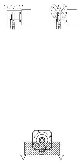
3.USAGE |
B-65262EN/06 |
If the cutting fluid is misted, the cutting fluid may be condensed on the inside of the cover and fall on the motor. Make sure that no condensed droplets fall on the motor.
Completely separate the machining area from the motor area, using a telescopic cover, accordion curtain, and so on. Note that partitions such as accordion curtains are consumable and require periodic inspection for damage.
Output shaft seal (oil seal)
For all models, the shaft of the servo motor is provided with an oil seal to prevent entry of oil and other fluids into the motor. It does not, however, completely prevent the entry of lubricant and other fluids depending on the working conditions. Note the following points on use.
When the motor is rotating, the oil seal has an effect of discharging any oil that enters, but if it is pressurized for a long time when the motor is stopped, it may allow oil to enter through the lip. When lubrication with an oil bath is conducted for gear engagement, for example, the oil level must be below the lip of the oil seal of the shaft, and the oil level must be adjusted so that the oil does nothing but splash on the lip.
Diameters of the oil seal lips of motor shafts
Motor model |
Oil seal diameter |
|
αiS 2, αiS 4, αiS 2 HV, αiS 4 HV, |
φ15 [mm] |
|
αiF 1, αiF 2 |
||
|
||
αiS 8, αiS 12, αiS 8 HV, αiS 12 HV, |
φ24 [mm] |
|
αiF 4, αiF 8, αiF 4 HV, αiF 8 HV |
||
|
||
αiS 22, αiS 30, αiS 40, |
|
|
αiS 22 HV, αiS 30 HV, αiS 40 HV, |
|
|
αiF 12, αiF 22, αiF 30, αiF 12 HV, αiF 22 HV |
φ35 [mm] |
|
|
||
(Only the straight shaft type of the following) |
|
|
αiS 50, αiS 50 HV, αiS 60, αiS 60 HV, αiF 40 |
|
|
* Including those equipped with fans. |
|
|
(Only the taper shaft type of the following) |
|
|
αiS 50, αiS 50 HV, αiS 60, αiS 60 HV, αiF 40 |
φ38 [mm] |
|
* Including those equipped with fans. |
|
|
αiS 100, αiS 200, αiS 100 HV, αiS 200 HV |
φ55 [mm] |
|
* Including those equipped with fans. |
||
|
||
αiS 300, αiS 500, αiS 300 HV, αiS 500 HV |
φ65 [mm] |
|
αiS 1000 HV |
φ80 [mm] |
- 14 -
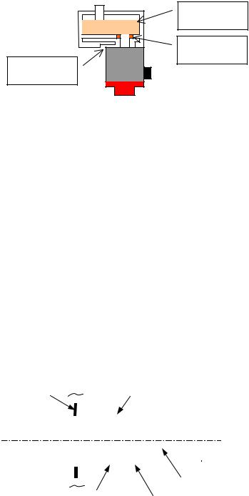
B-65262EN/06 |
3.USAGE |
|
|
|
|
|
Motor model |
Oil seal diameter |
|
αiS 2000 HV, αiS 3000 HV |
φ120 [mm] |
If the shaft is directed upward so that it is constantly immersed in oil, the oil seal of the motor alone does not provide sufficient sealing. If grease is used for lubrication, the properties of the oil seal are generally impaired. In these cases, a special design is required. For example, another oil seal is mounted on the machine side and a drain is provided so that any oil passing through that seal can is discharged outside.
Oil, grease
Oil seal
Drain hole
In such an environment in which the lip of the oil seal switches between dry and wet states repeatedly, if the cutting fluid flies about after the lip has worn in a dry state, the cutting fluid may easily enter the inside of the motor. In this case, provide a cover, etc. so that no cutting fluid is applied to the oil seal of the motor.
Ensure that no pressure is applied to the lip of the oil seal.
The cutting fluid does not provide lubrication for the oil seal lip, so that the fluid may easily enter the seal. Provide a cover so that no cutting fluid is applied to the oil seal.
The oil seal lip is made of rubber, and if foreign matters such as cutting chips get in, it will be easily worn, losing its sealing properties. Provide a cover, etc. to prevent cutting chips from entering near the lip.
Motor coupling
If a coupling box exists between the motor and the machine, employ the structure described below so that no cutting fluid builds up in the box.
Provide a cover for the top and sides of the coupling box.
Provide a drain hole at the bottom of the coupling box. The hole must be large enough to avoid clogging. Make sure that any cutting fluid that bounces back is not applied from the drain hole to the motor.
|
|
Partition |
|
|
|
|
|
|
|
|
|
|
Cover |
|
|
|
|
|
|
||
|
|
|
|
|
|
|
|
|
|
|
|
|
|
|
|
|
|
|
|
|
|
|
|
|
|
|
|
|
|
|
|
|
|
|
|
|
|
|
|
|
|
||
Machining area |
|
|
|
|
|
|
|
|
|
|
|
|
|
|
|
|
|
|
|
Motor area |
|
|
|
|
|
|
|
|
|
|
|
|
|
|
|
|
|
|
|
|
|||
|
|
|
|
|
|
|
|
|
|
|
|
|
|
|
|
|
|
|
|
|
|
|
|
|
|
|
|
|
|
|
|
|
|
|
|
|
|
|
|
|
|
|
|
|
|
|
|
|
|
|
|
|
|
|
|
|
|
|
|
|
|
|
|
|
|
|
|
|
|
|
|
|
|
|
|
|
|
|
|
|
|
|
|
|
|
|
|
|
|
|
|
|
|
|
|
|
|
|
|
|
|
|
|
|
|
|
|
|
|
|
|
|
|
|
|
|
|
|
|
|
|
|
|
|
|
|
|
|
|
|
|
|
|
|
|
|
|
|
|
|
|
|
|
|
|
|
|
|
|
|
|
|
|
|
|
|
|
|
|
|
|
|
|
|
|
|
|
|
|
|
|
|
|
|
|
|
|
|
|
|
|
|
|
|
|
|
|
|
|
|
|
|
|
|
|
|
|
|
|
|
|
|
|
|
|
|
|
|
|
|
|
|
|
|
|
|
|
|
|
|
|
|
|
|
|
|
|
|
|
|
|
|
|
|
|
|
|
|
|
|
|
|
|
|
|
|
|
|
|
|
|
|
|
|
|
|
|
|
|
|
|
|
|
|
|
|
|
|
Motor |
|
|
|
|
|
|
|
|
|
|
|
|
|
|
|
|
Drain |
Coupling box |
|
|
|
|
|
|
<Fault example>
The cutting fluid leaks from a gap in the accordion curtain to the motor area, and builds up in the coupling box. While the motor is moving, the cutting fluid ripples, splashing on the oil seal of the motor.
- 15 -
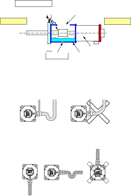
3.USAGE |
B-65262EN/06 |
The cutting fluid enters the inside of the motor there in large quantities, deteriorating the insulation of the motor.
Accordion curtain
There is a gap, so the cutting fluid enters the motor area. 
Machining area
No cover, thus the cutting fluid falls in the box.
Motor area
|
|
|
|
|
|
|
|
|
|
|
|
|
|
|
|
|
|
|
|
|
|
|
|
|
|
|
|
|
|
|
|
|
|
|
|
|
|
|
|
|
|
|
|
|
|
|
|
|
|
|
|
|
|
|
|
|
|
|
|
|
Motor |
|||
|
|
|
|
|
|
|
|
|
||||
|
|
|
|
|
|
|
|
|
Coupling box |
|||
|
|
|
|
|
|
|
|
|
||||
|
|
|
|
|
Drain |
|||||||
|
|
|
|
|
||||||||
|
|
|
|
|
|
|
|
|
||||
The hole is too small, and clogged.
Connectors
Note the following points on use:
Make sure that no cutting fluid is introduced to the motor via cables. If the motor connector is used horizontally, this can be accomplished by forming a slack in the cable.
If the motor connector is directed upward, the cutting fluid collects into the cable connector. Whenever possible, direct the motor connector sideways or downward.
If there is a possibility of the power cable and the power connector being wet, it is recommended to use the water-proof connector plug recommended in this DESCRIPTIONS for the connector and a oil-proof cable as the power cable. (Oil-proof cable example: PUR (polyurethane) series made by LAPP)
If using a conduit hose for cable protection purposes, use the seal adapter recommended in this DESCRIPTIONS.
- 16 -
 Loading...