


B-63945EN/03 |
8.EMBEDDED ETHERNET FUNCTION |
8 EMBEDDED ETHERNET FUNCTION
This chapter describes the specifications of the embedded Ethernet function.
Chapter 8, "EMBEDDED ETHERNET FUNCTION", consists of the following sections:
8.1 EMBEDDED ETHERNET PORT AND PCMCIA |
|
ETHERNET CARD .................................................................. |
602 |
8.2SETTING UP THE EMBEDDED ETHERNET FUNCTION .605
8.3SWITCHING BETWEEN THE EMBEDDED ETHERNET
|
DEVICES.................................................................................. |
645 |
8.4 |
EMBEDDED ETHERNET OPERATIONS ............................. |
646 |
8.5 |
RESTART OF THE EMBEDDED ETHERNET ..................... |
651 |
8.6 |
MAINTENANCE SCREEN FOR EMBEDDED |
|
|
ETHERNET FUNCTION......................................................... |
652 |
8.7 |
LOG SCREEN OF THE EMBEDDED ETHERNET |
|
|
FUNCTION............................................................................... |
657 |
- 601 -

8.EMBEDDED ETHERNET FUNCTION |
B-63945EN/03 |
8.1 EMBEDDED ETHERNET PORT AND PCMCIA ETHERNET CARD
The embedded Ethernet function can be used by selecting one of two types of devices: the embedded Ethernet port and PCMCIA Ethernet card.
A selection can also be made to stop the embedded Ethernet function. The PCMCIA Ethernet card is to be inserted into the memory card slot for temporary communication.
CAUTION
1When using the embedded Ethernet function for the first time, set an IP address and other items carefully as instructed by the network administrator, then perform a sufficient communication test.
Note that an incorrect IP address or other setting may cause a communication failure on the entire network.
2A unit such as a PC situated in the same network can increase the communication processing load on the CNC even if the unit is not communicating with the CNC.
Avoid connecting the CNC to a factory-wide network. Use a router or the like to separate the network including the CNC from the other networks.
NOTE
1The embedded Ethernet port of FANUC Series 32i-A is available as an option.
2Use the PCMCIA Ethernet card designated by
FANUC. General Ethernet cards available on the market cannot be used.
3The PCMCIA Ethernet card is used for FANUC
LADDER-III or SERVO GUIDE.
4Use the PCMCIA Ethernet card just for temporary communication as described above. Avoid using the card for continuous communication.
5The PCMCIA Ethernet card is inserted into a memory card slot, with a part of the card left uninserted. When using the PCMCIA Ethernet card, take great care not to damage the card by hitting the protruding part of the card.
When the card becomes unnecessary, remove the card immediately, in order to prevent any damage to the card.
- 602 -

B-63945EN/03 |
8.EMBEDDED ETHERNET FUNCTION |
Related NC parameters
|
|
|
#7 |
#6 |
#5 |
#4 |
#3 |
#2 |
#1 |
#0 |
|
|
14880 |
|
|
|
|
|
|
|
|
ETH |
|
[Input type] |
Setting input |
|
|
|
|
|
|
|
|||
[Data type] |
Bit |
|
|
|
|
|
|
|
|
||
# 0 |
ETH |
The embedded Ethernet function (embedded Ethernet port or |
|||||||||
|
|
|
PCMCIA Ethernet card) is: |
|
|
|
|
|
|||
0:Used.
1:Not used.
|
|
|
|
|
NOTE |
|
|
|
|
|
|
|
This parameter is valid with series 656F and edition |
||
|
|
|
|
|
06 or later. |
|
|
|
|
|
|
|
|
|
|
|
|
14896 |
|
|
Selection of embedded Ethernet with the 300is, 310is, and 320is of |
|
|
|
|
|
|
stand-alone type |
|
||
|
|
|
|
|
|
|
|
|
[Input type] |
|
Parameter input |
|
|
||
|
[Data type] |
|
Word |
|
|
||
[Valid data range] |
|
0 to 3 |
|
|
|||
|
|
|
|
|
Set embedded Ethernet usable with the 300is, 310is, and 320is of |
||
|
|
|
|
|
stand-alone type. |
|
|
|
|
|
|
|
0 : For the embedded Ethernet port, the connector (CD38A) for |
||
|
|
|
|
|
Ethernet on the control unit is used. |
||
|
|
|
|
|
For the PCMCIA Ethernet card, the card slot on the side of the |
||
|
|
|
|
|
display unit is used. |
|
|
|
|
|
|
|
1 : For the embedded Ethernet port, the connector (CD38A) for |
||
|
|
|
|
|
Ethernet on the control unit is used. |
||
|
|
|
|
|
For the PCMCIA Ethernet card, the card slot (CNM1B) on the |
||
|
|
|
|
|
control unit is used. |
|
|
|
|
|
|
|
2 : For the embedded Ethernet port, the connector (CD38S) for |
||
|
|
|
|
|
Ethernet on the rear of the display unit is used. |
||
|
|
|
|
|
For the PCMCIA Ethernet card, the card slot on the side of the |
||
|
|
|
|
|
display unit is used. |
|
|
|
|
|
|
|
3 : For the embedded Ethernet port, the connector (CD38S) for |
||
|
|
|
|
|
Ethernet on the rear of the display unit is used. |
||
|
|
|
|
|
For the PCMCIA Ethernet card, the card slot (CNM1B) on the |
||
|
|
|
|
|
control unit is used. |
|
|
|
|
|
|
|
|||
|
No.14896 |
|
embedded Ethernet port |
PCMCIA Ethernet card |
|||
|
0 |
|
|
Port in the CNC |
Memory card slot on a side of the display unit |
||
|
1 |
|
|
Port in the CNC |
Memory card slot in the CNC |
||
|
2 |
Port in the rear of the display unit |
Memory card slot on a side of the display unit |
||||
|
3 |
Port in the rear of the display unit |
Memory card slot in the CNC |
||||
NOTE
This parameter is valid with the FS300is/310is/320is-A of stand-alone type, and series 656F and edition 08 or later.
- 603 -

8.EMBEDDED ETHERNET FUNCTION |
B-63945EN/03 |
Notes on using Ethernet with Windows CE of FS300is/310is/320is-A
With the FS300is/310is/320is-A, the Ethernet interface on Windows
CE may be used by both of the embedded Ethernet function of the
CNC and application software on Windows CE.
Note that the restrictions below are imposed accordingly.
NOTE
1When the FS300is/310is/320is-A of LCD-mounted type is used and the PCMCIA Ethernet card is selected for the embedded Ethernet function, application software on Windows CE cannot use the embedded Ethernet port. When the embedded
Ethernet port is selected for the embedded Ethernet function, application software on Windows CE cannot use the PCMCIA Ethernet card.
2When the FS300is/310is/320is-A of stand-alone type is used, the connection location of the embedded Ethernet function varies according to the setting of NC parameter No. 14896. So, the restrictions below are applied to the Ethernet interface on Windows CE.
(1)When 0 is set in NC parameter No. 14896 and the PCMCIA Ethernet card is selected for the embedded Ethernet function, application software on Windows CE cannot use the embedded Ethernet port.
(2)When 1 is set in NC parameter No. 14896, application software on Windows CE can use the embedded Ethernet port and PCMCIA Ethernet card.
(3)When 2 is set in NC parameter No. 14896, the restriction on item 1 above (for the LCD-mounted type) is applied.
(4)When 3 is set in NC parameter No. 14896 and the embedded Ethernet port is selected for the embedded Ethernet function, application software on Windows CE cannot use the
PCMCIA Ethernet card.
3When the FS300is/310is/320is-A is used, application software on Windows CE can perform communication simultaneously on a port (embedded Ethernet port or PCMCIA Ethernet card) selected for the embedded Ethernet function.
- 604 -

B-63945EN/03 |
8.EMBEDDED ETHERNET FUNCTION |
8.2 SETTING UP THE EMBEDDED ETHERNET FUNCTION
This section describes the setting of parameters for the embedded
Ethernet function.
8.2.1 Setting of the FOCAS2/Ethernet Function
This subsection describes the settings required to operate the
FOCAS2/Ethernet function.
Notes on using the FOCAS2/Ethernet function for the first time
NOTE
1When running user's original application software created by using the FOCAS2/Ethernet function, use the embedded Ethernet port.
2The FOCAS2/Ethernet function allows up to five
FOCAS2/Ethernet clients to be connected to one
CNC.
3Concurrent access by multiple applications or personal computers may overload the CNC, reducing the communication speed.
- 605 -

8.EMBEDDED ETHERNET FUNCTION |
B-63945EN/03 |
8.2.1.1Operation on the FOCAS2/Ethernet setting screen
On the Ethernet parameter setting screen, set the parameters for operating the FOCAS2/Ethernet function.
Procedure
1Press the function key  .
.
2Soft keys [EMBED PORT] and [PCMCIA LAN] appear. (When there is no soft keys, press the continue key.)
3To display the Ethernet Setting screen for the embedded Ethernet port or the PCMCIA Ethernet card, press soft key [EMBED PORT] or [PCMCIA LAN], respectively.
4Press soft keys [COMMON] and [FOCAS2] and then enter parameters for the items that appear.
NOTE
1The parameters for the embedded Ethernet port and the parameters for the PCMCIA Ethernet card are independent of each other.
2The settings of the FOCAS2/Ethernet function for the PCMCIA Ethernet card are made when a connection to SERVO GUIDE and FANUC
LADDER-III is established.
- 606 -

B-63945EN/03 |
8.EMBEDDED ETHERNET FUNCTION |
COMMON screen (BASIC)
Press soft key [COMMON]. The COMMON screen (BASIC) is displayed.
COMMON screen (BASIC)
Settings items
Item |
Description |
IP ADDRESS |
Specify the IP address of the embedded Ethernet. |
|
(Example of specification format: "192.168.0.100") |
SUBNET MASK |
Specify a mask address for the IP addresses of the |
|
network. |
|
(Example of specification format: "255.255.255.0") |
ROUTER IP |
Specify the IP address of the router. |
ADDRESS |
Specify this item when the network contains a router. |
|
(Example of specification format: "192.168.0.253") |
Display items
Item |
Description |
MAC ADDRESS |
Embedded Ethernet MAC address |
AVAILABLE |
Enabled device of the embedded Ethernet. |
DEVICE |
Either the embedded Ethernet port or the PCMCIA |
|
Ethernet card is displayed. |
- 607 -
8.EMBEDDED ETHERNET FUNCTION |
B-63945EN/03 |
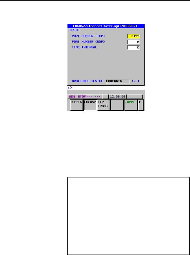
FOCAS2 screen
Press soft key [FOCAS2]. The FOCAS2 screen is displayed.
FOCAS2 screen
Setting items
Item |
Description |
PORT NUMBER |
Specify a port number to be used with the |
(TCP) |
FOCAS2/Ethernet function. The valid input range is |
|
5001 to 65535. |
PORT NUMBER |
Set this item to 0 when it is used as the |
(UDP) |
FOCAS2/Ethernet function. |
TIME INTERVAL |
Set this item to 0 when it is used as the |
|
FOCAS2/Ethernet function. |
NOTE
1When a connection to the CIMPLICITY i CELL is established, set the UDP port number and time interval above as described in the FANUC
CIMPLICITY i CELL Operator's Manual (B-75074).
2The unit of the time interval is 10 ms. The allowable range is between 10 and 65535. A time interval less than 100ms cannot be set.
3Decreasing the time interval setting increases the communication load and can affect the network performance.
Example) If the interval is set to 100 (100 x 10 ms
=1 second), broadcast data is sent every 1 second.
- 608 -
B-63945EN/03 8.EMBEDDED ETHERNET FUNCTION
Initial setting of the PCMCIA Ethernet card
The PCMCIA Ethernet card is factory-set to the following default values, for ease of connection with SERVO GUIDE or FANUC
LADDER-III. |
|
IP ADDRESS |
: 192.168.1.1 |
SUBNET MASK |
: 255.255.255.0 |
ROUTER IP ADDRESS |
: None |
PORT NUMBER (TCP) |
: 8193 |
PORT NUMBER (UDP) |
: 0 |
TIME INTERVAL |
: 0 |
If a specified IP address is changed to a blank (space), the specified setting is reset to the default value.
The embedded Ethernet port does not have a default value.
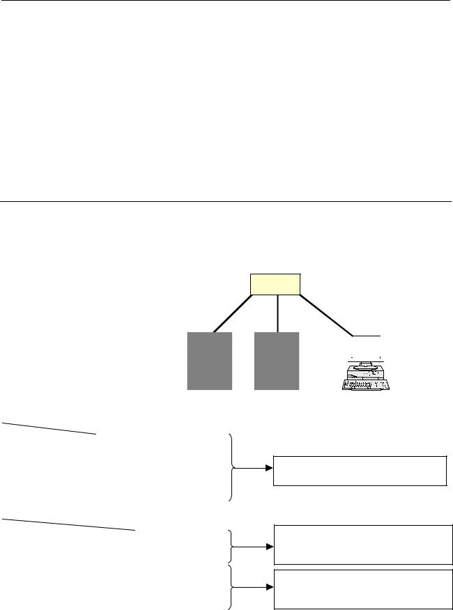
8.2.1.2Example of setting the FOCAS2/Ethernet function
The following shows a setting example required for the FOCAS2/Ethernet function to operate.
In this example, one personal computer is connected to two CNCs through FOCAS2/Ethernet.
|
|
|
|
|
|
CNC 1 |
|
|
|
|
|
|
|
|
|
|
CNC 1 |
|
CNC 2 |
|
IP address |
|
192.168.0.100 |
192.168.0.101 |
|||
Subnet mask |
|
255.255.255.0 |
255.255.255.0 |
|||
Router IP address |
None |
|
None |
|||
TCP port number |
8193 |
|
|
8193 |
||
UDP port number |
0 |
|
|
0 |
||
Time interval |
|
0 |
|
|
0 |
|
|
|
|
|
|
|
|
|
|
|
|
|
|
PC 1 |
IP address |
|
|
|
192.168.0.200 |
||
Subnet mask |
|
|
|
255.255.255.0 |
||
Default gateway |
|
|
|
None |
||
CNC 1 |
|
NC IP address |
|
192.168.0.100 |
||
|
|
NC TCP port |
|
|
8193 |
|
|
|
number |
|
|
|
|
CNC 2 |
|
NC IP address |
|
192.168.0.101 |
||
|
|
NC TCP port |
|
|
8193 |
|
|
|
number |
|
|
|
|
HUB
10BASE-T or 100BASE-TX
CNC 2 |
|
|
|
|
|
|
|
|
|
|
|
|
|
|
|
|
|
|
|
|
|
|
|
|
|
|
|
|
|
|
|
|
|
|
|
|
|
|
|
|
|
|
|
|
|
|
|
|
|
|
|
|
|
|
|
|
|
|
|
|
|
|
|
|
|
|
|
|
|
|
|
|
|
|
|
|
|
|
|
PC 1 |
|
|
|
||||||||||||
The Ethernet parameter screen is used for setting.
"Microsoft TCP/IP property" of the personal computer (Windows 95/98/NT/2000/XP) is used for setting.
The arguments of the data window library function cnc_allclibhndl3 are used for setting.
- 609 -

8.EMBEDDED ETHERNET FUNCTION |
B-63945EN/03 |
8.2.2 Setting of the FTP File Transfer Function
This section describes the settings required for the FTP file transfer function to operate using the embedded Ethernet function.
Notes on using the FTP file transfer function for the first time
NOTE
1When using the FTP file transfer function, use the embedded Ethernet port.
2The number of FTP communications to which one CNC can be connected using the FTP file transfer function is one.
8.2.2.1Operation on the FTP file transfer setting screen
On the Ethernet setting screen, set the parameters for operating the
FTP file transfer function.
Procedure
1Press the function key  .
.
2Soft keys [EMBED PORT] appear.
(When there is no soft keys, press the continue key.)
3By pressing the [EMBED PORT] soft key, the Ethernet Setting screen for the embedded Ethernet port is displayed.
4Press soft keys [COMMON] and [FTP TRANS] and then enter parameters for the items that appear.
NOTE
The parameters for the embedded Ethernet port and the parameters for the PCMCIA Ethernet card are independent of each other.
If the [PCMCIA LAN] soft key is pressed, the
PCMCIA Ethernet card can be set up. However, the card setup is carried out for maintenance and is not necessary usually.
- 610 -
B-63945EN/03 |
8.EMBEDDED ETHERNET FUNCTION |
COMMON screen (BASIC)
Press soft key [COMMON]. The COMMON screen (BASIC) is displayed.
COMMON screen (BASIC)
Setting items
Item |
Description |
IP ADDRESS |
Specify the IP address of the embedded Ethernet. |
|
(Example of specification format: "192.168.0.100") |
SUBNET MASK |
Specify a mask address for the IP addresses of the |
|
network. |
|
(Example of specification format: "255.255.255.0") |
ROUTER IP |
Specify the IP address of the router. |
ADDRESS |
Specify this item when the network contains a router. |
|
(Example of specification format: "192.168.0.253") |
Display items
Item |
Description |
MAC ADDRESS |
Embedded Ethernet MAC address |
AVAILABLE |
Enabled device of the embedded Ethernet. |
DEVICE |
Either the embedded Ethernet port or the PCMCIA |
|
Ethernet card is displayed. |
- 611 -
8.EMBEDDED ETHERNET FUNCTION |
B-63945EN/03 |
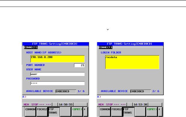
transfer screen (CONNECT1, CONNECT2, CONNECT3)
1Press soft key [FTP TRANS]. The FTP transfer screen is displayed.
2Page keys  can be used to make settings for the three host computers for connection destinations 1 to 3.
FTP transfer screen (1st page) |
FTP transfer screen (2nd page) |
|
|
|
|
|
Item |
Description |
|
HOST NAME |
Specify the IP address of the host computer. |
|
|
(Example of specification format: "192.168.0.200") |
|
PORT NUMBER |
Specify a port number to be used with the FTP file |
|
|
transfer function. An FTP session is used, so that "21" |
|
|
is to be specified usually. |
|
USERNAME |
Specify a user name to be used for logging in to the |
|
|
host computer with FTP. |
|
|
(Up to 31 characters can be specified.) |
|
PASSWORD |
Specify a password for the user name specified above. |
|
|
(Up to 31 characters can be specified.) |
|
|
Be sure to set a password. |
|
LOGIN FOLDER |
Specify a work folder to be used when logging in to the |
|
|
host computer. (Up to 127 characters can be |
|
|
specified.) |
|
|
If nothing is specified, the home folder specified in the |
|
|
host computer becomes the log-in folder. |
- 612 -

B-63945EN/03 |
8.EMBEDDED ETHERNET FUNCTION |
Operation
Select a destination.
1Pressing the [(OPRT)] soft key causes soft key [HOST SELECT] to be displayed. Pressing this soft key causes soft keys [CONECT 1], [CONECT 2], and [CONECT 3] to be displayed.
2Depending on the host computer to be connected, press soft key [CONECT 1], [CONECT 2], or [CONECT 3]. Destination 1, 2, or 3 is highlighted in the screen title field. The computer corresponding to the highlighted destination is selected as the target computer to be connected.
When destination 1 is selected
- 613 -

8.EMBEDDED ETHERNET FUNCTION |
B-63945EN/03 |
8.2.2.2Related NC parameters
|
|
|
The NC parameters related to the FTP file transfer function are |
|
|
|
|
described below. |
|
|
|
|
|
|
|
0020 |
|
I/O CHANNEL : Input/output device selection, or interface number for a |
|
|
|
foreground input device |
|
|
[Data type] |
Byte |
|||
[Valid data range] |
9 : Select the embedded Ethernet as the input/output device. |
|||
For embedded Ethernet port
|
|
|
#7 |
#6 |
#5 |
#4 |
#3 |
#2 |
#1 |
#0 |
|
|
14880 |
|
|
|
|
|
|
|
PCH |
|
|
[Input type] |
Setting input |
|
|
|
|
|
|
|
|||
[Data type] |
Bit |
|
|
|
|
|
|
|
|
||
# 1 |
PCH |
When communication based on the FTP file transfer function starts, an |
|||||||||
|
|
|
FTP server presence check based on PING is: |
|
|
|
|||||
0:Made
1:Not made
NOTE
Usually, set this parameter to 0 (to make a check). If this parameter is set to 1 (not to make an FTP server presence check based on PING), several tens of seconds may be required until an error is recognized when no FTP server is present on the network.
Mainly for security, a personal computer may be set to ignore the PING command. When communicating with such a personal computer, set this parameter to 1 (not to make an FTP server presence check based on PING).
- 614 -
B-63945EN/03 |
8.EMBEDDED ETHERNET FUNCTION |
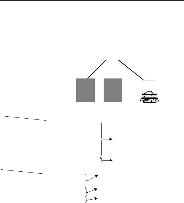
8.2.2.3Example of setting the FTP file transfer function
The following shows a setting example required for the FTP file transfer function to operate.
(WindowsXP Professional is used as the OS for the personal computer).
In this example, one personal computer is connected to two CNCs through the FTP file transfer function.
•On Personal Computer 1, the FTP server function operates.
•On CNC 1 and CNC 2, the FTP client operates as the FTP file transfer function.
|
|
|
|
|
|
|
|
|
|
|
|
|
|
|
|
|
|
|
|
|
|
|
|
|
|
|
|
|
|
|
|
|
|
|
|
|
|
|
|
|
|
|
|
|
|
|
|
|
|
|
|
|
|
|
|
|
|
|
|
|
|
|
|
|
|
|
|
|
|
|
|
|
|
|
|
|
|
|
|
|
|
|
|
|
|
|
|
|
|
|
|
|
|
|
|
|
|
|
|
|
|
|
CNC 1 |
|
|
CNC 2 |
|
|
|
|
|
|
|
|
|
|
|
|
|
|
|
|
||
|
|
|
|
|
|
|
|
|
|
|
|
|
|
|
|
|
|
|
|
|
||||
|
|
|
|
|
|
|
|
|
|
|
|
|
|
|
|
|
|
|
|
|
||||
|
|
|
|
|
|
|
|
|
|
|
|
|
|
|
|
|
|
|
|
|
||||
|
|
|
|
|
|
|
|
|
PC 1 |
|
||||||||||||||
|
|
|
|
|
|
|
|
|
|
|
|
|
|
|
|
|
|
|
|
|
|
|
|
|
|
|
CNC 1 |
CNC 2 |
|
|
|
|
|
|
|
|
|
|
|
|
|
|
|
|
|
|
|
|
|
IP address |
|
192.168.0.100 |
192.168.0.101 |
|
|
|
|
|
|
|
|
|
|
|
|
|
|
|
|
|
|
|
|
|
Subnet mask |
|
255.255.255.0 |
255.255.255.0 |
|
|
|
|
|
|
|
|
|
|
|
|
|
|
|
|
|
|
|
|
|
Router IP address |
None |
None |
|
|
|
|
|
|
|
|
|
|
|
|
|
|
|
|
|
|
|
|
||
Connection |
Port number |
21 |
21 |
|
|
|
|
The Ethernet parameter screen is used for |
|
|||||||||||||||
host 1 |
IP address |
192.168.0.200 |
192.168.0.200 |
|
|
|
|
setting. |
|
|||||||||||||||
|
User name |
user |
user |
|
|
|
|
|
|
|
|
|
|
|
|
|
|
|
|
|
|
|
|
|
|
|
|
|
|
|
|
|
|
|
|
|
|
|
|
|
|
|
|
|
|
||||
|
Password |
user |
user |
|
|
|
|
|
|
|
|
|
|
|
|
|
|
|
|
|
|
|
|
|
|
|
|
|
|
|
|
|
|
|
|
|
|
|
|
|
|
|
|
|
|
||||
|
Login DIR |
None |
None |
|
|
|
|
The parameter screen is used for setting. |
|
|||||||||||||||
NC parameter No. 20 |
9 |
9 |
|
|
|
|
|
|
|
|
|
|
|
|
|
|
|
|
|
|
|
|
||
|
|
|
|
|
|
|
|
|
|
|
|
|
|
|
|
|
|
|
|
|
|
|
|
|
|
|
|
|
|
|
|
|
|
|
|
|
|
|
|||||||||||
|
|
PC 1 |
|
|
|
"Microsoft TCP/IP property" of the personal computer |
|
|||||||||||||||||
IP address |
|
192.168.0.200 |
|
|
(WindowsXP) is used for setting. |
|
||||||||||||||||||
Subnet mask |
|
255.255.255.0 |
|
|
|
|
|
|
|
|
|
|
|
|
|
|
|
|
|
|
|
|
|
|
|
|
|
|
|
|
|
|
|
|
|
|
|
|
|
|
|
|
|
|
|
|
|||
|
|
|
"User acount” of the personal computer (WindowsXP) |
|
||||||||||||||||||||
Default gateway |
None |
|
|
|
|
|||||||||||||||||||
|
|
|
is used for setting. |
|
||||||||||||||||||||
User name |
|
user |
|
|
|
|
||||||||||||||||||
|
|
|
|
|
|
|
|
|
|
|
|
|
|
|
|
|
|
|
|
|
|
|
||
Password |
|
user |
|
|
|
|
|
|
|
|
|
|
|
|
|
|
|
|
|
|
|
|
|
|
|
|
|
|
"Internet service manager" of the personal computer |
|
|||||||||||||||||||
Login DIR |
|
Default |
|
|
|
|
||||||||||||||||||
|
|
|
|
(WindowsXP) is used for setting. |
|
|||||||||||||||||||
|
|
|
|
|
|
|
||||||||||||||||||
|
|
|
|
|
|
|
|
|
|
|
|
|
|
|
|
|
|
|
|
|
|
|
|
|
- 615 -

8.EMBEDDED ETHERNET FUNCTION |
B-63945EN/03 |
8.2.3 Setting Up the DNS/DHCP Function
The DHCP/DNS function is set up by using the COMMON screen (DETAIL) and NC parameters.
8.2.3.1Setting up DNS
This subsection describes the procedure for setting up a DNS.
Procedure
1Enable the DNS function, with reference to "Related NC Parameters," which will be seen later.
2Set up the DNS server of the host computer.
3Connect the host computer on which the DNS server is working (hereafter referred to as a DNS server), reboot the CNC, then press function key  .
.
4Press soft keys [EMBED PORT] and [COMMON] in that order. The COMMON screen (DETAIL) appears.
5Enter the IP address of the DNS server in the corresponding DNS IP address field.
COMMON screen (DETAIL)
After pressing soft key [COMMON], press either page key
to call a desired COMMON screen (DETAIL). Specify a
DNS IP address.
COMMON screen (DETAIL)
- 616 -

B-63945EN/03 8.EMBEDDED ETHERNET FUNCTION
Display items
Item |
Description |
DNS IP |
Up to two DNS IP addresses can be specified. |
ADDRESS 1, 2 |
The CNC searches for the DNS server using DNS IP |
|
addresses 1 and 2 in that order. |
8.2.3.2Setting up DHCP
This subsection describes the procedure for setting up a DHCP.
Procedure
1Enable the DHCP function, with reference to "Related NC Parameters," which will be seen later.
2Set up the DHCP server of the host computer.
3Connect the host computer on which the DHCP server is working (hereafter referred to as a DHCP server), reboot the CNC, then press function key  .
.
4Press soft keys [EMBED PORT] and [COMMON] in that order. The COMMON screen appears.
5If the DHCP function of the CNC has been enabled and if the DHCP server is connected successfully, the DHCP server automatically specifies the following items.
-IP ADDRESS
-SUBNET MASK
-ROUTER IP ADDRESS
-DNS IP ADDRESS
-DOMAIN
If the DHCP server cannot be connected, "DHCP ERROR" is displayed in each field.
6If the DNS function has also been enabled and if the DHCP server and the DNS server work together (if the DNS server supports dynamic DNS), enter a host name.
- 617 -

|
8.EMBEDDED ETHERNET FUNCTION |
B-63945EN/03 |
|
|
|
|
|
|
COMMON screen (basic and detail) |
|
|
|
After pressing soft key |
[COMMON], press either page key |
|
to call a desired Ethernet common setting screen (basic,
detail).
If the DHCP server is connected successfully and if the setting data can be obtained, the screen is displayed as shown below.
When the DHCP server is connected successfully
If the host name is not specified, the CNC automatically assigns a host name in the "NC-<MAC-address>" format.
Example of automatically assigned host name
If the DHCP server cannot be connected, the screen is displayed as shown below.
When the DHCP server cannot be connected
- 618 -
 Loading...