


 Loading...
FANUC Robot ARC Mate 100i MODEL B FANUC Robot M-6i MODEL B
MAINTENANCE MANUAL
B--81545EN/01
B--81545EN/01 |
PREFACE |
|
|
PREFACE
This manual explains the maintenance and connection procedures for the mechanical units (R--J3i controller) of the following robots. Before replacing the purts, determine the specification number of the mechanical unit.:
Model name
FANUC Robot ARC Mate 100i MODEL B
(With J2 and J3--axis brake)
FANUC Robot ARC Mate 100i MODEL B
(With all axes brake)
FANUC Robot M--6i MODEL B (With J2 and J3--axis brake)
FANUC Robot M--6i MODEL B (With all axes brake)
Abbreviation |
Mechanical unit |
|
specification No. |
||
|
||
|
A05B--1215--B201 |
|
ARC Mate 100i |
|
|
MODEL B |
|
|
|
A05B--1215--B601 |
|
|
A05B--1215--B202 |
|
M--6i MODEL B |
|
|
|
A05B--1215--B602 |

|
|
PREFACE |
B--81545EN/01 |
||||||
|
|
|
|
|
|
|
|
|
|
|
|
|
|
|
|
|
|
|
|
|
|
|
|
|
|
|
|
|
|
|
|
|
|
|
|
|
|
|
|
|
|
|
|
|
|
|
|
|
|
|
|
|
|
|
|
|
|
|
|
|
|
|
|
|
|
|
|
|
|
|
|
|
|
|
|
|
|
|
|
|
|
|
|
|
|
|
|
|
|
|
|
|
|
|
|
|
|
|
|
|
|
|
|
|
|
|
|
|
|
|
|
|
|
|
|
|
|
|
|
|
|
|
|
|
|
|
|
|
|
|
|
|
|
|
|
|
|
|
|
No. |
(1) |
|
CONTENTS |
MODEL |
|
|
FANUC Robot ARC Mate 100i |
|
|
MODEL B (2--axis brake) |
|
|
FANUC Robot ARC Mate 100i |
|
LETTERS |
MODEL B (6--axis brake) |
|
FANUC Robot M--6i MODEL B |
||
|
||
|
(2--axis brake) |
|
|
FANUC Robot M--6i MODEL B |
|
|
(6--axis brake) |
(2) |
(3) |
(4) |
(5) |
|
TYPE |
No. |
DATE |
WEIGHT |
|
(Without controller) |
||||
|
|
|
||
A05B--1215--B201 |
|
|
184 kg |
|
A05B--1215--B601 |
138 kg |
|||
|
SERIAL |
PRODUCTION |
|
|
|
YEAR AND |
|
||
A05B--1215--B201 |
NO. |
184 kg |
||
MONTH |
||||
|
|
|
||
A05B--1215--B601 |
|
|
138 kg |

B--81545EN/01 |
PREFACE |
|
|
Specification
Item |
|
Type |
|
Controlled axes |
|
Installation |
|
Motion range |
J1 axis rotation |
(Maximum speed) |
J2 axis rotation |
|
|
|
J3 axis rotation |
|
J4 axis wrist rotation |
|
J5 axis wrist swing |
|
J6 axis wrist rotation |
Maximum speed |
J1 axis |
|
J2 axis |
|
J3 axis |
|
J4 axis |
|
J5 axis |
|
J6 axis |
Max. load capacity at wrist |
|
Max. load capacity on J3 catting |
|
Allowable load moment at wrist |
J4 axis |
|
J5 axis |
|
J6 axis |
Allowable load inertia at wrist |
J4 axis |
|
J5 axis |
|
J6 axis |
Drive method |
|
Repeatability |
|
Weight of mechanical unit |
|
Installation environment
R--2000i/165F
Articulated type
6 axes (J1, J2, J3, J4, J5, J6)
Floor, Upside--dowm (Wall & Angle mount) (Note 1) 340° (5.93rad)
250° (4.36rad)
315° (5.60rad)
380° (6.63rad)
280° (4.89rad)
720° (12.57rad)
150°/s (2.62rad/s)
160°/s (2.79rad/s)
170°/s (2.97rad/s)
400°/s (6.98rad/s)
400°/s (6.98rad/s)
500°/s (8.73rad/s) 6kg
12kg 15.7N·m (1.8kgf·m) 9.8N·m (1.0kgf·m) 5.9N·m (0.5kgf·m)
0.63kg·m2 (6.4kgf·cm·s2) 0.22kg·m2 (2.2kgf·cm·s2)
0.061kg·m2 (0.62kgf·cm·s2) Electric servo drive by AC servo motor
0.06mm
|
134kg (2--axis brake type) |
|
138kg (6--axis brake type) |
Ambient temperature : 0 -- 45°C |
|
Ambient humidity |
: Normally :75%RH or less |
|
: Short time 95%RH or less |
|
(within 1 month) |
|
(No dew or frost allowed) |
Vibration |
: 0.5G (4.9m/s2) or less |
NOTE
1 Under the installation condition within ( ), the J1 and J2 axis motion range will be limited.

PREFACE |
B--81545EN/01 |
|
|
Dust--proof/waterproof performance of M--6i B
Normal specification
Wrist+J3 arm |
IP67 |
Other part |
IP54 |
NOTE
Definition of IP code Definition of IP 67
6=Dust--tight
7=Protection from water immersion Definition of IP 54
5=Dust--protected
4=Protection from splashing water
Performance of resistant chemicals and resistant solvents
(1)(1) The robot (including severe dust/liquid protection model) cannot be used with the following liquids because there is feat that rubber parts (packing, oil seal, O ring etc.) will corrode.
(a)Organic solvcnts
(b)Coolant including chlorine / gasoline
(c)Acid, alkali and liquid causing rust
(d)Other liquids or solutions, that will harm NBR
(2)When the robots work in the environment, using water or liquid, complete draining of J1 base must be done. Incomplete draining of J1 base will make the robot break down.
B--81545EN/01 |
PREFACE |
|
|
RELATED MANUALS |
For the FANUC Robot series, the following manuals are available: |
||
Safety handbook B--80687EN |
|
Intended readers : |
|
|
|
|
All persons who use FANUC Robot, system designer |
All persons who use the FANUC Robot and system de- |
Topics : |
||
signer must read and understand thoroughly this handbook |
Safety items for robot system design, operation, maintenance |
||
R--J3i MODEL B controller |
Setup and Operations |
Intended readers : |
|
|
manual |
Operator, programmer, maintenance person, system designer |
|
|
|
|
Topics : |
|
SPOT TOOL |
Robot functions, operations, programming, setup, interfaces, alarms |
|
|
|
B--81464EN--1 |
Use : |
|
HANDLING TOOL |
Robot operation, teaching, system design |
|
|
|
B--81464EN--2 |
|
|
ARC TOOL |
|
|
|
|
B--81464EN--3 |
|
|
SEALING TOOL |
|
|
|
|
B--81464EN--4 |
|
|
Maintenance manual |
Intended readers : |
|
|
|
B--81465EN |
Maintenance person, system designer |
|
|
|
Topics : |
|
|
B--81465EN--1 |
Installation, connection to peripheral equipment, maintenance |
|
|
(European |
Use : |
|
|
specification) |
Installation, start--up, connection, maintenance |
Mechanical unit |
Maintenance manual |
Intended readers : |
|
|
FANUC Robot ARC Mate |
Maintenance person, system designer |
|
|
100i B |
Topics : |
|
|
M--6i B |
Installation, connection to the controller, maintenance |
|
|
B--81545EN |
Use : |
|
|
|
|
installation, start--up, connection, maintenance |

B--81545EN/01 |
Table of Contents |
I. MAINTENANCE
1. CONFIGURATION . . . . . . . . . . . . . . . . . . . . . . . . . . . . . . . . . . . . . . . . . . . . . . . . . . . . . . . . . . . . 3
1.1 |
J1--AXIS DRIVE MECHANISM . . . . . . . . . . . . . . . . . . . . . . . . . . . . . . . . . . . . . . . . . . . . . . . . . . . . . . |
4 |
1.2 |
J2--AXIS DRIVE MECHANISM . . . . . . . . . . . . . . . . . . . . . . . . . . . . . . . . . . . . . . . . . . . . . . . . . . . . . . |
5 |
1.3 |
J3--AXIS DRIVE MECHANISM . . . . . . . . . . . . . . . . . . . . . . . . . . . . . . . . . . . . . . . . . . . . . . . . . . . . . . |
6 |
1.4 |
J4--AXIS DRIVE MECHANISM . . . . . . . . . . . . . . . . . . . . . . . . . . . . . . . . . . . . . . . . . . . . . . . . . . . . . . |
7 |
1.5 |
J5-- AND J6--AXIS DRIVE MECHANISMS . . . . . . . . . . . . . . . . . . . . . . . . . . . . . . . . . . . . . . . . . . . . |
8 |
1.6 |
SPECIFICATIONS OF THE MAJOR MECHANICAL UNIT COMPONENTS . . . . . . . . . . . . . . . . . |
9 |
2. PREVENTIVE MAINTENANCE . . . . . . . . . . . . . . . . . . . . . . . . . . . . . . . . . . . . . . . . . . . . . . . . 11
2.1 |
DAILY INSPECTION . . . . . . . . . . . . . . . . . . . . . . . . . . . . . . . . . . . . . . . . . . . . . . . . . . . . . . . . . . . . . |
12 |
2.2 |
QUARTERLY INSPECTION . . . . . . . . . . . . . . . . . . . . . . . . . . . . . . . . . . . . . . . . . . . . . . . . . . . . . . . |
14 |
2.3 |
YEARLY INSPECTION . . . . . . . . . . . . . . . . . . . . . . . . . . . . . . . . . . . . . . . . . . . . . . . . . . . . . . . . . . . |
15 |
2.4 |
ONE-- AND HALF--YEAR PERIODIC INSPECTION . . . . . . . . . . . . . . . . . . . . . . . . . . . . . . . . . . . |
16 |
2.5 |
THREE--YEAR PERIODIC INSPECTION . . . . . . . . . . . . . . . . . . . . . . . . . . . . . . . . . . . . . . . . . . . . |
17 |
2.6 |
MAINTENANCE TOOLS . . . . . . . . . . . . . . . . . . . . . . . . . . . . . . . . . . . . . . . . . . . . . . . . . . . . . . . . . . |
18 |
3. PERIODIC MAINTENANCE . . . . . . . . . . . . . . . . . . . . . . . . . . . . . . . . . . . . . . . . . . . . . . . . . . 19
3.1 GREASING . . . . . . . . . . . . . . . . . . . . . . . . . . . . . . . . . . . . . . . . . . . . . . . . . . . . . . . . . . . . . . . . . . . . . 20 3.2 GREASE REPLACEMENT . . . . . . . . . . . . . . . . . . . . . . . . . . . . . . . . . . . . . . . . . . . . . . . . . . . . . . . . 22 3.3 BATTERY REPLACEMENT . . . . . . . . . . . . . . . . . . . . . . . . . . . . . . . . . . . . . . . . . . . . . . . . . . . . . . . 25
4. TROUBLESHOOTING . . . . . . . . . . . . . . . . . . . . . . . . . . . . . . . . . . . . . . . . . . . . . . . . . . . . . . |
26 |
4.1 OVERVIEW . . . . . . . . . . . . . . . . . . . . . . . . . . . . . . . . . . . . . . . . . . . . . . . . . . . . . . . . . . . . . . . . . . . . . 27 4.2 TROUBLES AND CAUSES . . . . . . . . . . . . . . . . . . . . . . . . . . . . . . . . . . . . . . . . . . . . . . . . . . . . . . . . 28 4.3 COMPONENT REPLACEMENT AND ADJUSTMENT ITEMS . . . . . . . . . . . . . . . . . . . . . . . . . . . 31
5. ADJUSTMENTS . . . . . . . . . . . . . . . . . . . . . . . . . . . . . . . . . . . . . . . . . . . . . . . . . . . . . . . . . . . . 32
5.1 |
REFERENCE POSITION AND MOVING RANGE . . . . . . . . . . . . . . . . . . . . . . . . . . . . . . . . . . . . . |
33 |
5.2 |
SIMPLIFIED MASTERING . . . . . . . . . . . . . . . . . . . . . . . . . . . . . . . . . . . . . . . . . . . . . . . . . . . . . . . . |
37 |
5.3 |
MASTERING BY ZERO POSITION MARK ALIGNMENT . . . . . . . . . . . . . . . . . . . . . . . . . . . . . . |
39 |
5.4 |
JIG--BASED MASTERING . . . . . . . . . . . . . . . . . . . . . . . . . . . . . . . . . . . . . . . . . . . . . . . . . . . . . . . . . |
41 |
5.5 |
CONFIRMING MASTERING . . . . . . . . . . . . . . . . . . . . . . . . . . . . . . . . . . . . . . . . . . . . . . . . . . . . . . . |
47 |
5.6 |
J5--AXIS GEAR BACKLASH ADJUSTMENTS . . . . . . . . . . . . . . . . . . . . . . . . . . . . . . . . . . . . . . . . |
48 |
5.7 |
BRAKE RELEASE . . . . . . . . . . . . . . . . . . . . . . . . . . . . . . . . . . . . . . . . . . . . . . . . . . . . . . . . . . . . . . . |
50 |
6. COMPONENT REPLACEMENT AND ADJUSTMENTS . . . . . . . . . . . . . . . . . . . . . . . . . . 52
6.1 |
REPLACING THE J1--AXIS MOTOR M1 . . . . . . . . . . . . . . . . . . . . . . . . . . . . . . . . . . . . . . . . . . . |
53 |
6.2 |
REPLACING THE J1--AXIS REDUCER . . . . . . . . . . . . . . . . . . . . . . . . . . . . . . . . . . . . . . . . . . . . . . |
55 |
6.3 |
REPLACING THE J2--AXIS MOTOR M2 . . . . . . . . . . . . . . . . . . . . . . . . . . . . . . . . . . . . . . . . . . . |
57 |
6.4 |
REPLACING THE J2--AXIS REDUCER . . . . . . . . . . . . . . . . . . . . . . . . . . . . . . . . . . . . . . . . . . . . . . |
59 |
6.5 |
REPLACING THE J3--AXIS MOTOR M3 . . . . . . . . . . . . . . . . . . . . . . . . . . . . . . . . . . . . . . . . . . . |
62 |
6.6 |
REPLACING THE J3--AXIS REDUCER . . . . . . . . . . . . . . . . . . . . . . . . . . . . . . . . . . . . . . . . . . . . . . |
64 |

TABLE OF CONTENTS |
B--81545EN/01 |
|
6.7 |
REPLACING THE J4--AXIS MOTOR M4 . . . . . . . . . . . . . . . . . . . . . . . . . . . . . . . . . . |
. . . . . . . . . 66 |
6.8 |
REPLACING THE J4--AXIS GEARBOX . . . . . . . . . . . . . . . . . . . . . . . . . . . . . . . . . . . . . . |
. . . . . . . . 67 |
6.9 |
REPLACING THE J5--AXIS MOTOR M5 . . . . . . . . . . . . . . . . . . . . . . . . . . . . . . . . . . . |
. . . . . . . . 69 |
6.10 |
REPLACING THE J5--AXIS GEAR . . . . . . . . . . . . . . . . . . . . . . . . . . . . . . . . . . . . . . . . . . |
. . . . . . . . 71 |
6.11 |
REPLACING THE J6--AXIS MOTOR M6 AND REDUCER . . . . . . . . . . . . . . . . . . . . |
. . . . . . . . 73 |
7. PIPING AND WIRING . . . . . . . . . . . . . . . . . . . . . . . . . . . . . . . . . . . . . . . . . . . . . . . . . . . . . . . 77
7.1 PIPING DRAWING . . . . . . . . . . . . . . . . . . . . . . . . . . . . . . . . . . . . . . . . . . . . . . . . . . . . . . . . . . . . . . . 78 7.2 WIRING DIAGRAMS . . . . . . . . . . . . . . . . . . . . . . . . . . . . . . . . . . . . . . . . . . . . . . . . . . . . . . . . . . . . . 79 7.3 CABLE MOUNTING DIAGRAM . . . . . . . . . . . . . . . . . . . . . . . . . . . . . . . . . . . . . . . . . . . . . . . . . . . 81
8. CABLE REPLACEMENT . . . . . . . . . . . . . . . . . . . . . . . . . . . . . . . . . . . . . . . . . . . . . . . . . . . . |
82 |
8.1 CABLE DRESSING . . . . . . . . . . . . . . . . . . . . . . . . . . . . . . . . . . . . . . . . . . . . . . . . . . . . . . . . . . . . . . 83 8.2 REPLACING CABLES . . . . . . . . . . . . . . . . . . . . . . . . . . . . . . . . . . . . . . . . . . . . . . . . . . . . . . . . . . . . 85
9. COVER OPTION REPLACEMENT . . . . . . . . . . . . . . . . . . . . . . . . . . . . . . . . . . . . . . . . . . . . 90
9.1 |
REPLACING THE J2 COVER OPTION (A05B--1210--J401) . . . . . . . . . . . . . . . . . . . . . . . . . . . . . . |
91 |
9.2 |
REPLACING THE J4 COVER OPTION (A05B--1210--J402) . . . . . . . . . . . . . . . . . . . . . . . . . . . . . . |
92 |
10. M--6i PACKAGES WITH REINFORCED DUST--PROOF AND |
|
|
DRIP--PROOF CHARACTERISTICS . . . . . . . . . . . . . . . . . . . . . . . . . . . . . . . . . . . . . . . . . |
93 |
|
10.1DUST--PROOF AND DRIP--PROOF PERFORMANCE OF THE PACKAGES WITH
REINFORCED DUST--PROOF AND DRIP--PROOF CHARACTERISTICS . . . . . . . . . . . . . . . . . . |
94 |
10.2CONFIGURATION OF THE PACKAGES WITH REINFORCED DUST--PROOF AND
DRIP--PROOF CHARACTERISTICS . . . . . . . . . . . . . . . . . . . . . . . . . . . . . . . . . . . . . . . . . . . . . . . . . |
95 |
10.3CAUTIONS IN SELECTING THE PACKAGES WITH REINFORCED DUST--PROOF
AND DRIP--PROOF CHARACTERISTICS . . . . . . . . . . . . . . . . . . . . . . . . . . . . . . . . . . . . . . . . . . . . |
97 |
10.4REPLACING THE COMPONENTS OF THE PACKAGES WITH REINFORCED DUST--PROOF
AND DRIP--PROOF CHARACTERISTICS . . . . . . . . . . . . . . . . . . . . . . . . . . . . . . . . . . . . . . . . . . . . |
98 |
II. CONNECTION
1. ROBOT OUTLINE DRAWING AND OPERATION AREA DIAGRAM . . . . . . . . . . . . . 103
1.1 OUTLINE DRAWING AND OPERATION AREA DIAGRAM . . . . . . . . . . . . . . . . . . . . . . . . . . . 104
2. MOUNTING DEVICES ON THE ROBOT . . . . . . . . . . . . . . . . . . . . . . . . . . . . . . . . . . . . . . 107
2.1 |
WRIST SECTION END EFFECTOR MOUNTING SURFACE . . . . . . . . . . . . . . . . . . . . . . . . . . . |
108 |
2.2 |
DEVICE MOUNTING SURFACES . . . . . . . . . . . . . . . . . . . . . . . . . . . . . . . . . . . . . . . . . . . . . . . . . |
109 |
2.3 |
SETTING THE SYSTEM VARIABLES FOR SHORTEST--TIME CONTROL . . . . . . . . . . . . . . . |
111 |
2.4 |
WRIST LOAD CONDITIONS . . . . . . . . . . . . . . . . . . . . . . . . . . . . . . . . . . . . . . . . . . . . . . . . . . . . . |
114 |
2.5 |
END EFFECTOR AIR PIPING . . . . . . . . . . . . . . . . . . . . . . . . . . . . . . . . . . . . . . . . . . . . . . . . . . . . . |
115 |
2.6 |
END EFFECTOR INPUT SIGNALS (RDI/RDO) . . . . . . . . . . . . . . . . . . . . . . . . . . . . . . . . . . . . . . |
116 |
2.7 |
CONNECTOR SPECIFICATIONS . . . . . . . . . . . . . . . . . . . . . . . . . . . . . . . . . . . . . . . . . . . . . . . . . . |
117 |
B--81545EN/01 |
TABLE OF CONTENTS |
|
|
3. TRANSPORTATION AND INSTALLATION . . . . . . . . . . . . . . . . . . . . . . . . . . . . . . . . . . . . 118
3.1 TRANSPORTATION . . . . . . . . . . . . . . . . . . . . . . . . . . . . . . . . . . . . . . . . . . . . . . . . . . . . . . . . . . . . . 119 3.2 STORING THE ROBOT . . . . . . . . . . . . . . . . . . . . . . . . . . . . . . . . . . . . . . . . . . . . . . . . . . . . . . . . . . 121 3.3 INSTALLATION . . . . . . . . . . . . . . . . . . . . . . . . . . . . . . . . . . . . . . . . . . . . . . . . . . . . . . . . . . . . . . . . 122 3.4 MAINTENANCE CLEARANCE . . . . . . . . . . . . . . . . . . . . . . . . . . . . . . . . . . . . . . . . . . . . . . . . . . . 125 3.5 ASSEMBLING THE ROBOT FOR INSTALLATION . . . . . . . . . . . . . . . . . . . . . . . . . . . . . . . . . . . 127 3.6 AIR PIPING . . . . . . . . . . . . . . . . . . . . . . . . . . . . . . . . . . . . . . . . . . . . . . . . . . . . . . . . . . . . . . . . . . . . 128 3.7 INSTALLATION CONDITIONS . . . . . . . . . . . . . . . . . . . . . . . . . . . . . . . . . . . . . . . . . . . . . . . . . . . 130
APPENDIX
A. SPARE PARTS LISTS . . . . . . . . . . . . . . . . . . . . . . . . . . . . . . . . . . . . . . . . . . . . . . . . . . . . . 133 B. INTRA--MECHANICAL UNIT CONNECTION DIAGRAMS . . . . . . . . . . . . . . . . . . . . . . 139 C. PERIODIC INSPECTION TABLE . . . . . . . . . . . . . . . . . . . . . . . . . . . . . . . . . . . . . . . . . . . . 144 D. BOLT MOUNTING TORQUE LIST . . . . . . . . . . . . . . . . . . . . . . . . . . . . . . . . . . . . . . . . . . . 145
I. MAINTENANCE
B--81545EN/01 |
MAINTENANCE |
1. CONFIGURATION |
|
|
|
1 CONFIGURATION
Fig. 1 shows the configuration of the mechanical unit.
AC servo motor for J4--axis (M4)
AC servo motor for J3--axis (M3)
AC servo motor for J1--axis (M1)
J3--axis arm
AC servo motor for J5--axis (M5)
AC servo motor for J6--axis (M6)
Wrist unit
J3--axis casing
J2--axis arm
AC servo motor for J2--axis (M2)
J2--axis base
J1--axis base
Fig 1 Mechanical unit configuration
1. CONFIGURATION |
MAINTENANCE |
B--81545EN/01 |
|
|
|
1.1
J1--AXIS DRIVE MECHANISM
Fig. 1.1 shows the J1--axis drive mechanism.
The J1--axis drive mechanism is configured in such a way that the J2--axis base is rotated by reducing the rotation speed of an AC servo motor with a reducer.
The J2--axis base is supported on the J1--axis base through the reducer.
J1--axis AC servo motor |
J2--axis base |
J1--axis reducer |
J1--axis base |
Fig 1.1 J1--axis drive mechanism
B--81545EN/01 |
MAINTENANCE |
1. CONFIGURATION |
|
|
|
1.2
J2--AXIS DRIVE MECHANISM
Fig. 1.2 shows the J2--axis drive mechanism. The J2--axis drive mechanism is configured in such a way that the J2--axis arm is rotated by reducing the rotation speed of an AC servo motor with a reducer.
The J2--axis arm is supported on the J2--axis base through the reducer.
J2--axis AC servo motor |
J2--axis arm |
J2--axis base |
|
|
J2--axis reducer |
Fig 1.2 J2--axis drive mechanism
1. CONFIGURATION |
MAINTENANCE |
B--81545EN/01 |
|
|
|
1.3
J3--AXIS DRIVE MECHANISM
Fig. 1.3 shows the J3--axis drive mechanism. The J3--axis drive mechanism is configured in such a way that the J3--axis casing is rotated by reducing the rotation speed of an AC servo motor with a reducer.
The J3--axis casing is supported on the J2--axis arm through the reducer.
J3--axis reducer |
J3--axis AC servo motor |
J3--axis casing |
J2--axis arm |
Fig 1.3 J3--axis drive mechanism

B--81545EN/01 |
MAINTENANCE |
1. CONFIGURATION |
|
|
|
1.4
J4--AXIS DRIVE MECHANISM
Fig. 1.4 shows the J4--axis drive mechanism. The J4--axis drive mechanism is configured in such a way that the J3--axis arm is rotated by reducing the rotation speed of an AC servo motor with a two--stage gear.
J3--axis arm |
Final gear |
Second gear |
J3--axis casing |
Input gear |
J4--axis AC servo motor |
Fig 1.4 J4--axis drive mechanism

1. CONFIGURATION |
MAINTENANCE |
B--81545EN/01 |
|
|
|
1.5
J5-- AND J6--AXIS DRIVE MECHANISMS
Fig. 1.5 shows the J5-- and J6--axis drive mechanisms. The J5--axis drive mechanism is configured in such a way that the J6--axis unit is rotated by reducing the rotation speed of an AC servo motor with a three--stage gear. The J6--axis drive mechanism is configured in such a way that the output flange is rotated by reducing the rotation speed of an AC servo motor with a reducer.
J5--axis AC servo motor |
J6--axis unit |
J6--axis AC servo motor |
|
|
Output flange |
Input gear |
|
|
Second gear |
Final gear |
J6--axis reducer |
|
|
|
|
Third gear |
|
Fig 1.5 J5-- and J6--axis drive mechanisms
B--81545EN/01 |
MAINTENANCE |
1. CONFIGURATION |
|
|
|
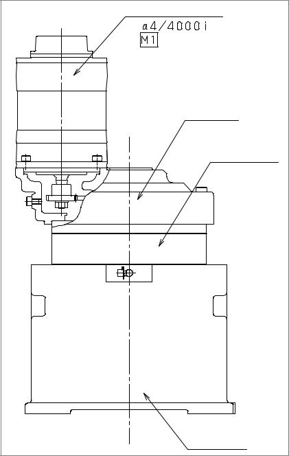
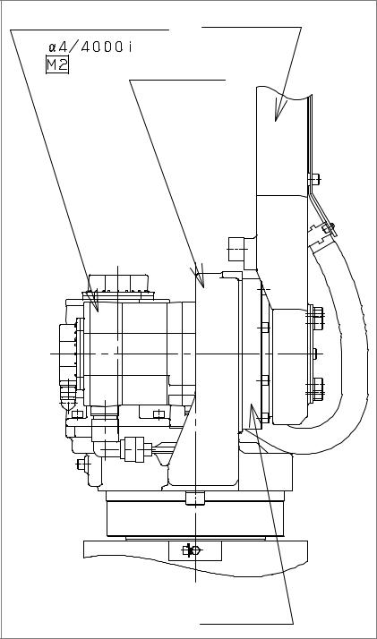
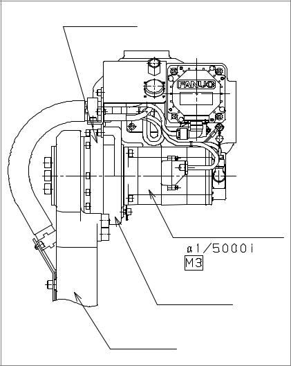
1.6
SPECIFICATIONS OF THE MAJOR MECHANICAL UNIT COMPONENTS
1)Motors
ARC Mate 100i MODEL B
(two--axis, equipped with a brake): A05B--1215--B201
M--6i MODEL B
(two--axis, equipped with a brake): A05B--1215--B202
Specification |
Axis |
|
Remark |
A06B-0223-B005 |
J1 |
α 4/4000i |
|
|
|||
|
|
|
|
A06B-0223-B605 |
J2 |
α 4/4000i |
Equipped with a brake |
|
|
|
|
A06B-0202-B605 |
J3 |
α 1/5000i |
Equipped with a brake |
|
|
|
|
A06B-0202-B005 |
J4 |
α 1/5000i |
|
|
|
|
|
A06B-0115-B075#0008 |
J5 |
β M0.5/4000 |
|
|
|
|
|
A06B-0114-B075#0008 |
J6 |
β M0.4/4000 |
|
|
|
|
|
ARC Mate 100i MODEL B |
|
|
|
|
|
(six--axis, equipped with a brake): A05B-- |
1215 |
--B601 |
|||
M--6i MODEL B |
|
|
|
|
|
(six--axis, equipped with a brake): A05B-- |
1215-- |
B602 |
|||
|
|
|
|
|
|
Specification |
|
Axis |
|
|
Remark |
|
|
|
|
|
|
A06B-0223-B605 |
|
J1 |
α 4/4000i |
Equipped with a brake |
|
|
|
|
|
|
|
A06B-0223-B605 |
|
J2 |
α 4/4000i |
Equipped with a brake |
|
|
|
|
|
|
|
A06B-0202-B605 |
|
J3 |
α 1/5000i |
Equipped with a brake |
|
|
|
|
|
|
|
A06B-0202-B605 |
|
J4 |
α 1/5000i |
Equipped with a brake |
|
|
|
|
|
||
A06B-0115-B275#0008 |
|
J5 |
β M0.5/4000 |
||
|
|
|
Equipped with a brake |
||
|
|
|
|
||
A06B-0114-B275#0008 |
|
J6 |
β M0.4/4000 |
||
|
|
|
Equipped with a brake |
||
|
|
|
|
|
|
2) Reducers |
|
|
|
|
|
|
|
|
|
|
|
Specification |
|
Axis |
|
|
|
|
|
|
|
|
|
A97L-0218-0288#33 |
|
J1 |
|
|
|
|
|
|
|
|
|
A97L-0218-0289#153 |
|
J2 |
|
|
|
|
|
|
|
|
|
A97L-0218-0295#161 |
|
J3 |
|
|
|
|
|
|
|
|
|
A97L-0218-0224 |
|
J6 |
|
|
|
|
|
|
|
|
|
3) J4--axis gearbox |
|
|
|
|
|
|
|
|
|
|
|
Specification |
|
Axis |
|
|
|
|
|
|
|
|
|
A05B-1215-K401 |
|
J4 |
|
|
|
|
|
|
|
|
|

1. CONFIGURATION MAINTENANCE B--81545EN/01
4) Gears
Specification |
Axis |
|
A290-7215-X511 |
J5 |
|
|
|
|
A290-7215-V501 |
J5 |
|
|
|
|
A290-7215-V502 |
J5 |
|
|
|
|
A290-7215-X514 |
J5 |
|
|
|
5) Stoppers
Specification |
Axis |
|
|
A290-7215-X241 |
J1 |
Note) 330° stopper |
|
|
|||
|
|
|
|
A290-7215-X323 |
J2 |
|
|
|
|
|
|
A290-7215-X324 |
J3 |
|
|
|
|
|
B--81545EN/01 |
MAINTENANCE |
2. PREVENTIVE MAINTENANCE |
|
|
|
2 PREVENTIVE MAINTENANCE
Performing daily inspection, periodic inspection, and maintenance can keep the performance of robots in a stable state for a long period.

2. PREVENTIVE MAINTENANCE |
MAINTENANCE |
B--81545EN/01 |
|
|
|
2.1
DAILY INSPECTION
Clean and maintain each component of robots during everyday system operations. At the same time, check the components to see if there is a crack or break in them. Also check and maintain the following items as required.
a) Before automatic operation
No. |
Inspection item |
Inspection procedure |
|
1 |
|
Pneumatic pressure |
Make a pneumatic pressure |
|
|||
|
|
check |
check, using the three--piece |
|
|
|
pneumatic option shown in Fig. |
|
|
|
2.1. |
|
|
|
If the measured pneumatic pres- |
|
|
|
sure does not fall in the range |
|
|
|
between 0.5 and 0.7 MPa (5 and |
|
|
|
7 kg/cm2), make adjustments, |
|
|
|
using the regulator pressure set- |
|
|
|
ting handle. |
|
|
|
|
2 |
|
Check on the amount of |
Put the pneumatic pressure sys- |
|
|
oil mist |
tem in operation and check the |
|
For |
|
amount of oil dripping. If the |
|
machines |
|
measured amount of oil dripping |
|
with a |
|
does not meet the rating (one |
|
three--piece |
|
drop/10 to 20 seconds), make |
|
pneumatic |
|
adjustments, using the oil ad- |
|
option |
|
justment knob. The oiler be- |
|
|
|
comes empty after 10 to 20 days |
|
|
|
of normal operation. |
|
|
|
|
3 |
|
Check on the amount of |
Check to see if the amount of oil |
|
|
oil |
in the three--piece option is with- |
|
|
|
in the rated level shown in Fig. |
|
|
|
2.1. |
|
|
|
|
4 |
|
Check for leakage from |
Check to see if a joint or hose |
|
|
the piping |
leaks. |
|
|
|
If you find a problem, tighten the |
|
|
|
joint or replace any defective |
|
|
|
component. |
|
|
|
|
5Whether cables are abnormal Mechanical unit
6Battery voltage check
See Chapter 8.
Make sure that when the power is turned on, the BLAL alarm has not been raised. If the BLAL alarm has been raised, replace the battery as directed in Section 3.3.
7 |
Whether there is any abnormal vibra- |
Check that each axis is running |
|
tion, noise, or heat generation in motors |
smoothly. |
|
|
|
8 |
Whether there is a change to positioning |
Check to see if there is any dis- |
|
precision |
placement from the previous |
|
|
position and there are variations |
|
|
in the stop position. |
|
|
|
B--81545EN/01 |
|
MAINTENANCE |
2. PREVENTIVE MAINTENANCE |
|
|
|
|
|
|
No. |
|
Inspection item |
|
Inspection procedure |
|
|
|||
|
|
|
|
|
9Reliable operation of peripheral equipment
Check to see if the machine operates exactly according to directions from the robot and peripheral equipment.
10 Check on the operation of the J2-- and See Section 4.2. J3--axis brakes.
Oiler’s oil inlet |
Oiler adjustment knob |
|||||||
|
|
|
|
|
|
|
|
Check oiler’s oil level |
|
|
|
|
|
|
|
|
|
|
|
|
|
|
|
|
|
|
|
|
|
|
|
|
|
|
|
|
|
|
|
|
|
|
|
|
|
|
|
|
|
|
|
|
|
|
|
|
|
|
|
|
|
|
|
|
|
|
|
|
|
|
|
|
Oiler |
Filter |
Pressure gauge |
Regulator pressure setting handle |
Fig 2.1 Three--piece pneumatic option
b)After automatic operation
Once you are finished with automatic operation, bring the robot to its reference position, and turn it off.
No. |
Inspection item |
Inspection procedure |
|
1 |
Component cleaning |
Clean and maintain each component. At the |
|
|
and inspection |
same time, check the components to see if |
|
|
|
there is a crack or break in them. |
|
|
|
|
2. PREVENTIVE MAINTENANCE |
MAINTENANCE |
B--81545EN/01 |
|
|
|
2.2
QUARTERLY INSPECTION
Inspect the following items at regular intervals of three months. Increase the locations and the frequency of inspection if the conditions under which the robot is used and the environment in which it runs require so.
No. |
Inspection item |
Inspection procedure |
|
1 |
Loose connector |
Check that the motor connectors or other con- |
|
|
|
nectors are not loose. |
|
|
|
|
|
2 |
Loose bolt |
Check that the cover retaining bolts or external |
|
|
|
bolts are not loose. |
|
|
|
|
|
3 |
Debris removal |
Remove any spatter, debris, and dust from the |
|
|
|
mechanical unit. |
|
|
|
|
B--81545EN/01 |
MAINTENANCE |
2. PREVENTIVE MAINTENANCE |
|
|
|
2.3
YEARLY INSPECTION
Inspect the following item at regular intervals of one year.
No. |
Inspection item |
Inspection procedure |
|
1 |
Greasing |
See Section 3.1. |
|
|
|
|
2. PREVENTIVE MAINTENANCE |
MAINTENANCE |
B--81545EN/01 |
|
|
|
2.4
ONE-- AND HALF--YEAR PERIODIC INSPECTION
Perform the following inspection/maintenance item at regular intervals of one year and half.
No. |
Inspection item |
Inspection procedure |
|
1 |
Battery replacement |
Replace the battery in the mechanical unit. |
|
|
|
(See Section 3.3.) |
|
|
|
|
B--81545EN/01 |
MAINTENANCE |
2. PREVENTIVE MAINTENANCE |
|
|
|
2.5
THREE--YEAR PERIODIC INSPECTION
No. |
Inspection item |
Inspection procedure |
|
1 |
Grease replacement |
See Section 3.2. |
|
|
|
|
2. PREVENTIVE MAINTENANCE |
MAINTENANCE |
B--81545EN/01 |
|
|
|
2.6
MAINTENANCE TOOLS
You should have the following instruments and tools ready for maintenance.
a) |
Measuring instruments |
|
|
|
||
|
|
|
|
|
|
|
|
Instrument |
|
Condition |
|
Use |
|
|
|
|
|
|
||
Dial gauge |
|
1/100mm |
|
For positioning precision and backlash |
||
|
|
|
|
|
measurement |
|
|
|
|
|
|
|
|
Calipers |
|
150mm |
|
|
|
|
|
|
|
|
|
|
|
b) |
Tools |
|
|
|
|
|
|
Phillips screwdrivers |
(large, medium, and small sizes) |
||||
|
Flat--blade screwdrivers |
(large, medium, and small sizes) |
||||
|
Box wrenches |
|
(M3 to M6) |
|
||
|
Allen wrenches |
(M3 to M16) |
|
|||
|
Torque wrench |
|
|
|
|
|
|
Long T wrenches |
(M5 and M6) |
|
|||
|
Adjustable wrenches |
(medium and small sizes) |
||||
|
Pliers |
|
|
|
|
|
Long--nose pliers
Cutting pliers
Both--ended wrench
Grease gun
C--ring pliers
Flashlight
B--81545EN/01 |
MAINTENANCE |
3. PERIODIC MAINTENANCE |
|
|
|
3 PERIODIC MAINTENANCE

3. PERIODIC MAINTENANCE |
MAINTENANCE |
B--81545EN/01 |
|
|
|
3.1
GREASING
When greasing the robot, keep its power turned off.
i)Roughly speaking, replenish the robot with grease once a year.
ii)See Fig. 3.1 and Table 3.1 for greasing points and the method.
Table. 3.1 Greasing points
|
Greasing |
Specified |
Amount |
Greasing method |
|
No. |
of |
||||
|
point |
grease |
grease |
|
|
|
|
|
|
||
1 |
J6--axis |
Mori White |
40cc |
J6--axis grease inlet and out- |
|
|
reducer |
RE No.00 |
|
let, and attach the supplied |
|
|
|
(Specification: |
|
grease nipple to the grease in- |
|
|
|
A97L-0040-0119) |
|
let. After greasing, remove the |
|
|
|
|
|
grease nipple, and attach the |
|
|
|
|
|
flat--head bolts and sealing |
|
|
|
|
|
washers to the grease inlet |
|
|
|
|
|
and outlet. |
|
|
|
|
|
|
CAUTION
If you grease incorrectly, the pressure in the grease bath may increase steeply, leading to a broken seal, which will eventually cause grease leakage or malfunction.
When greasing, be sure to follow the cautions stated in Section 3.2.

B--81545EN/01 |
MAINTENANCE |
3. PERIODIC MAINTENANCE |
|
|
|
Grease nipple at the grease inlet for the J3-axis reducer
Seal bolt at the grease outlet for the J1-axis reducer
Grease nipple at the grease inlet for the J4-axis reducer
Low head bolt and seal washer at the grease outlet for the J5-axis reducer
Low head bolt and seal washer at the grease outlet for the J6-axis reducer
Low head bolt and seal washer at the grease outlet for the J4-axis reducer
Low head bolt and
seal washer at the grease outlet for the J6-axis reducer
Low head bolt and seal washer at the grease inlet for the J5-axis reducer
Grease nipple at the grease inlet for the J2-axis reducer
Grease nipple at the grease outlet for the J1-axis reducer
Seal bolt at the grease outlet for the J3-axis reducer
Seal bolt at the grease outlet for the
J2-axis reducer (2 locations)
Fig 3.1 Greasing points

3. PERIODIC MAINTENANCE |
MAINTENANCE |
B--81545EN/01 |
|
|
|
3.2
GREASE REPLACEMENT
Follow the procedure stated below to replace the grease in the J1--, J2--, and J3--axis reducers and the J4-- and J5--axis gearboxes once every three years or after 11,520 hours of operation. See Fig. 3.1 for greasing points.
1)Remove the seal bolts from the J1--, J2--, and J3--axis grease outlets shown in Fig. 3.1. Also remove the flat--bolts and sealing washers
from the J4-- and J5--axis grease outlets.
2)Uncap the grease nipples at the J1--, J2--, J3--, and J4--axis grease inlets. Remove the flat--head bolt from the J5--axis grease inlet and attach the supplied grease nipple to the J5--axis grease inlet.
3)Supply the grease specified in Table 3.2 to the J1--, J2--, and J3--axis reducers, and J4-- and J5--axis gearboxes through their respective grease nipples. Keep greasing until the new grease pushes out the old grease and comes out from each grease outlet. Ensure that the amount of the newly supplied grease equals the amount of the drained grease so that the grease bath will not become full.
4)Wind sealing tape around the J1--, J2--, and J3--axis seal bolts you removed, and attach them to the respective grease outlets.
5)Attach the J4-- and J5--axis flat--head bolts and the J4-- and J5--axis sealing washers to the respective grease inlets and outlets.
Table. 3.2 Grease to be replaced at regular intervals of three years
J1--axis reducer
J2--axis reducer
J3--axis reducer
J4--axis gearbox
J5--axis gearbox
Specified grease |
Amount of |
Robot pos- |
|
grease to be |
ture when |
|
||
Kyodo Yushi |
applied (cc) |
greased |
|
|
|
Mori White RE No.00 (Specification: A98L-0040-0119#2.4KG)
About 1100 |
-- |
|
|
About 570 |
-- |
|
|
About 300 |
-- |
|
|
About 700 |
-- |
|
|
About 400 |
J4=+90° |
|
|
Loading...