


 Loading...
GE Fanuc Automation
Computer Numerical Control Products
Laser C1000 / C2000 / C4000―Model E for CE Mark
Maintenance Manual
GFZ-70315EN/01 |
May 2001 |

GFL-001
Warnings, Cautions, and Notes as Used in this Publication
Warning
Warning notices are used in this publication to emphasize that hazardous voltages, currents, temperatures, or other conditions that could cause personal injury exist in this equipment or may be associated with its use.
In situations where inattention could cause either personal injury or damage to equipment, a Warning notice is used.
Caution
Caution notices are used where equipment might be damaged if care is not taken.
Note
Notes merely call attention to information that is especially significant to understanding and operating the equipment.
This document is based on information available at the time of its publication. While efforts have been made to be accurate, the information contained herein does not purport to cover all details or variations in hardware or software, nor to provide for every possible contingency in connection with installation, operation, or maintenance. Features may be described herein which are not present in all hardware and software systems. GE Fanuc Automation assumes no obligation of notice to holders of this document with respect to changes subsequently made.
GE Fanuc Automation makes no representation or warranty, expressed, implied, or statutory with respect to, and assumes no responsibility for the accuracy, completeness, sufficiency, or usefulness of the information contained herein. No warranties of merchantability or fitness for purpose shall apply.
©Copyright 2001 GE Fanuc Automation North America, Inc.
All Rights Reserved.

B-70315EN/01 TABLE OF CONTENTS
TABLE OF CONTENTS
1 OVERVIEW......................................................................................................................................... |
1 |
|
1.1 |
ORGANIZATION OF THE MANUAL ............................................................................................. |
2 |
1.2 |
APPLICABLE MODELS................................................................................................................... |
3 |
1.3 |
RELATED MANUALS...................................................................................................................... |
4 |
1.4 |
TO USE THE LASER OSCILLATOR SAFETY .............................................................................. |
5 |
2 SAFETY .............................................................................................................................................. |
6 |
|
2.1 |
LASER BEAM ................................................................................................................................... |
7 |
2.2 |
HIGH VOLTAGE............................................................................................................................. |
12 |
2.3 |
SAFETY ENCLOSURE (AT YOUR WORK STATION) ............................................................... |
16 |
2.4 |
FIRE ................................................................................................................................................. |
17 |
2.5 |
TOXIC FUME.................................................................................................................................. |
18 |
2.6 |
HIGH TEMPERATURE.................................................................................................................. |
19 |
2.7 |
WARNING LABELS ....................................................................................................................... |
23 |
2.8 |
HIGH-PRESSURE GAS.................................................................................................................. |
34 |
2.9 |
KEY CONTROL............................................................................................................................... |
35 |
2.10 |
SHUTTER LOCK ............................................................................................................................ |
36 |
2.11 |
EMERGENCY STOP BUTTON ..................................................................................................... |
37 |
2.12 |
WARNING LIGHT (OPTIONAL)................................................................................................... |
38 |
3 |
INTERNAL STRUCTURE................................................................................................................ |
39 |
||
|
3.1 |
GENERAL ....................................................................................................................................... |
40 |
|
|
3.2 |
COMPONENT DETAILS................................................................................................................ |
44 |
|
4 |
INSTALLATION............................................................................................................................... |
52 |
||
|
4.1 |
INSTALLATION PROCEDURE .................................................................................................... |
53 |
|
|
4.2 |
PREPARATION PRIOR TO SHIPMENT...................................................................................... |
62 |
|
|
4.2.1 |
Packing for Transportation ..................................................................................................... |
63 |
|
|
4.2.2 |
Removing Cooling Water......................................................................................................... |
64 |
|
|
4.3 |
DETAILS OF CHECKING ............................................................................................................. |
66 |
|
|
4.4 |
OSCILLATOR CONNECTIONS .................................................................................................... |
73 |
|
|
4.4.1 |
Cooling Water .......................................................................................................................... |
73 |
|
|
4.4.2 |
Laser Gas.................................................................................................................................. |
77 |
|
|
4.4.3 |
Electrical Connection............................................................................................................... |
78 |
|
|
4.4.4 |
Inter-unit Connections ............................................................................................................ |
85 |
|
c - 1
TABLE OF CONTENTS |
B-70315EN/01 |
|||
5 |
MAINTENANCE .............................................................................................................................. |
86 |
||
|
5.1 |
DAILY INSPECTION ..................................................................................................................... |
87 |
|
|
5.2 |
PERIODIC MAINTENANCE ......................................................................................................... |
88 |
|
|
5.3 |
DETAILS OF MAINTENANCE ..................................................................................................... |
89 |
|
|
5.3.1 |
Turbo Blower Oil...................................................................................................................... |
91 |
|
|
5.3.2 |
Exhaust Pump Oil ................................................................................................................... |
93 |
|
|
5.3.3 |
Exhaust Pump Filter ............................................................................................................... |
94 |
|
|
5.4 |
MAINTENANCE PARTS................................................................................................................ |
95 |
|
6 |
TROUBLESHOOTING..................................................................................................................... |
99 |
||
|
6.1 |
TROUBLESHOOTING PROCEDURE ........................................................................................ |
100 |
|
|
6.2 |
ERROR MESSAGES AND COUNTERMEASURES .................................................................. |
101 |
|
|
6.3 |
RESPONDING TO ALARM MESSAGES ON THE SCREEN ................................................... |
102 |
|
|
6.4 |
MAJOR FAULTS........................................................................................................................... |
128 |
|
|
6.4.1 Laser Power Supply Alarm Display ..................................................................................... |
128 |
||
|
6.4.2 Power Supply Cannot Be Switched Off Using CRT/MDI Switch ....................................... |
129 |
||
|
6.4.3 Power Supply Cannot Be Switched On Using CRT/MDI Switch........................................ |
129 |
||
|
6.4.4 Laser Output Just After Switch On Is Low ......................................................................... |
129 |
||
|
6.4.5 Display of Fluctuating Laser Output On CRT..................................................................... |
129 |
||
|
6.4.6 Electromagnetic Contactor of Exhaust Pump Trips Thermally ......................................... |
130 |
||
|
6.4.7 |
Main Breaker Trips ............................................................................................................... |
130 |
|
|
6.4.8 Excessive Laser Gas Consumption....................................................................................... |
131 |
||
|
6.4.9 |
Inverter Alarm Display ......................................................................................................... |
131 |
|
|
6.5 |
OBSERVING VOLTAGE OF POWER LINE .............................................................................. |
135 |
|
|
6.5.1 |
Measurement of Voltage........................................................................................................ |
135 |
|
|
6.5.2 |
Phase Relation ....................................................................................................................... |
135 |
|
|
6.5.3 Measurement of Voltage of DC Power Supply Unit ............................................................ |
135 |
||
|
6.5.4 Checking the IF PCB Signals................................................................................................ |
137 |
||
|
6.5.5 Checking the Jumper Pins.................................................................................................... |
137 |
||
|
6.6 |
INDICATION OF STATE BY MEANS OF SELF DIAGNOSTIC FUNCTION ........................ |
138 |
|
|
6.6.1 Data Items Displayed on the Diagnosis Screen................................................................... |
138 |
||
|
6.6.2 Laser Oscillator Status Display ............................................................................................ |
139 |
||
7 |
OSCILLATOR CONNECTIONS .................................................................................................... |
147 |
||
|
7.1 |
ELECTRICAL CONNECTIONS .................................................................................................. |
148 |
|
|
7.2 |
COOLING WATER PIPING......................................................................................................... |
151 |
|
|
7.3 |
GAS PIPING.................................................................................................................................. |
154 |
|
c - 2
B-70315EN/01 |
|
TABLE OF CONTENTS |
||
8 |
UNIT CONFIGURATION .............................................................................................................. |
158 |
||
|
8.1 |
INPUT UNIT ................................................................................................................................. |
159 |
|
|
8.2 |
INTERMEDIATE PCB B.............................................................................................................. |
164 |
|
|
8.3 |
GAS CONTROLLER (C1000-E).................................................................................................... |
165 |
|
|
8.4 |
PRESSURE CONTROL UNIT ..................................................................................................... |
168 |
|
9 |
SETTING AND ADJUSTMENT .................................................................................................... |
170 |
||
|
9.1 |
LASER POWER SUPPLY UNIT.................................................................................................. |
171 |
|
|
9.1.1 Preparatory Settings and Checks......................................................................................... |
171 |
||
|
9.1.2 |
Base Discharge Adjustment.................................................................................................. |
172 |
|
|
9.1.3 |
Maximum Output Adjustment.............................................................................................. |
173 |
|
|
9.1.4 |
Check ...................................................................................................................................... |
173 |
|
|
9.1.5 RFI and DCV Value Recording and Adjustment................................................................. |
174 |
||
9.1.6Alarm Processing after Modification of Intra-tube Pressure at Oscillation Time and
|
Bias Command Setting.......................................................................................................... |
174 |
9.1.7 Checking of Electric Shutter Operation ............................................................................... |
175 |
|
9.1.8 Alarm Level of Laser PSU..................................................................................................... |
176 |
|
9.2 |
TURBO PCB .................................................................................................................................. |
177 |
9.3 |
INVERTER .................................................................................................................................... |
179 |
9.3.1 Adjusting the Inverter (A90L-0001-0500/8LF : Model Name SJH300).............................. |
179 |
|
9.3.2 Adjusting the Inverter (A90L-0001-0464/CE, Model Name : JH300) ................................ |
189 |
|
9.4 |
GAS CONTROLLER ..................................................................................................................... |
195 |
9.4.1 Setting the Gas Supply Pressure Sensor ............................................................................. |
195 |
|
9.4.2 Setting the Atmospheric Pressure Sensor............................................................................ |
195 |
|
9.4.3 Adjusting the Exhaust Unit (Adjusting the Laser Gas Consumption) .............................. |
197 |
|
9.5SETTING THE GAS SUPPLY PRESSURE SENSOR AND ATMOSPHERIC PRESSURE
SENSOR......................................................................................................................................... |
199 |
|
9.5.1 |
Names of Components........................................................................................................... |
199 |
9.5.2 |
Setting Procedure .................................................................................................................. |
201 |
9.6 PRESSURE CONTROL UNIT ..................................................................................................... |
204 |
|
9.6.1 Setting the Gas Supply Pressure Sensor ............................................................................. |
204 |
|
9.6.2 Setting the Atmospheric Pressure Sensor............................................................................ |
205 |
|
9.7ADJUSTING THE EXHAUST CONTROL UNIT
|
(ADJUSTING THE LASER GAS CONSUMPTION) .................................................................. |
206 |
9.8 |
SETTING THE POWER INPUT COMPENSATION COEFFICIENT ...................................... |
207 |
9.9 |
WATER FLOW SENSOR.............................................................................................................. |
208 |
9.9.1 Adjusting the Water Flow Sensor (C1000-E)....................................................................... |
208 |
|
c - 3
TABLE OF CONTENTS |
B-70315EN/01 |
||
9.9.2 Adjusting the Flow Sensor (C2000-E, C4000-E).................................................................. |
210 |
||
9.10 |
DISCHARGE AGING.................................................................................................................... |
211 |
|
10 |
REPLACEMENT PROCEDURES .............................................................................................. |
216 |
|
10.1 |
INPUT UNIT ................................................................................................................................. |
217 |
|
10.1.1 Replacing the Stabilized Power Supply................................................................................ |
217 |
||
10.1.2 Replacing the Input Unit Control PCB ................................................................................ |
217 |
||
10.1.3 Replacing the IF PCB on the Oscillator Side....................................................................... |
218 |
||
10.2 |
REPLACING THE LASER POWER SUPPLY ............................................................................ |
219 |
|
10.3 |
REPLACING THE MATCHING BOX ......................................................................................... |
224 |
|
10.4 |
REPLACING THE TURBO BLOWER......................................................................................... |
225 |
|
10.5 |
REPLACING THE TURBO PCB.................................................................................................. |
227 |
|
10.6 |
REPLACING INTERMEDIATE PCB B ...................................................................................... |
228 |
|
10.7 |
REPLACING THE EXHAUST PUMP ......................................................................................... |
229 |
|
10.8 |
REPLACING THE PRESSURE CONTROL UNIT..................................................................... |
231 |
|
10.8.1 |
Gas Controller (C1000-E)...................................................................................................... |
231 |
|
10.8.2 Pressure Control Unit (C2000-E, C4000-E) ......................................................................... |
232 |
||
10.9 |
REPLACING THE EXHAUST CONTROL UNIT (C2000-E, C4000-E)..................................... |
233 |
|
10.10 |
REPLACING A DISCHARGE TUBE....................................................................................... |
234 |
|
10.11 |
REPLACING A FAN UNIT ...................................................................................................... |
236 |
|
10.11.1 Replacing a Fan Unit......................................................................................................... |
236 |
||
10.11.2 Replacing a Fan-assisted Radiator ................................................................................... |
237 |
||
10.11.3 Attaching and Detaching a Cable To and From the Terminal Block ............................. |
238 |
||
10.12 |
REPLACING THE POWER SENSOR UNIT........................................................................... |
239 |
|
10.13 |
REPLACING THE SHUTTER SECTION ............................................................................... |
240 |
|
10.13.1 Replacing the Shutter Unit ............................................................................................... |
241 |
||
10.13.2 Replacing the Shutter Mirror............................................................................................ |
241 |
||
10.13.3 Replacing the Shutter Switch (Thermal and Photoelectric Switches) ........................... |
241 |
||
10.14 |
REPLACING THE BEAM ABSORBER................................................................................... |
242 |
|
10.15 |
REPLACING THE INVERTER................................................................................................ |
243 |
|
10.16 |
REPLACING THE WATER DISTRIBUTION UNIT.............................................................. |
244 |
|
10.17 |
REPLACING THE CONDENSATION SENSOR.................................................................... |
248 |
|
10.18 |
REPLACING THE GUIDE LASER.......................................................................................... |
249 |
|
10.19 |
REPLACING THE TRIGGER ELECTRODE.......................................................................... |
250 |
|
11 |
LASER OPTICAL SYSTEM........................................................................................................ |
252 |
|
11.1 |
CLEANING AND REPLACING THE OPTICAL PARTS ........................................................... |
253 |
|
11.1.1 Cleaning and Replacing the Output Mirror......................................................................... |
254 |
||
c - 4
B-70315EN/01 |
TABLE OF CONTENTS |
|||
|
11.1.2 Cleaning and Replacing the Rear Mirror............................................................................. |
|
257 |
|
|
11.1.3 Cleaning and Replacing the Folding Mirrors....................................................................... |
|
260 |
|
|
11.1.4 Cleaning and Replacing the Zero-shift Mirror and Circular Polarization Mirror............. |
263 |
||
|
11.2 |
ALIGNMENT OF THE RESONATOR......................................................................................... |
|
265 |
|
11.2.1 Method of Obtaining a Maximum Power by Adjusting All Mirrors ................................... |
269 |
||
|
11.2.2 Alignment Procedure during Installation after Transportation......................................... |
|
271 |
|
|
11.2.3 Alignment Procedure at Mirror Cleaning Time................................................................... |
|
272 |
|
|
11.2.4 Obtaining a Maximum Power ............................................................................................... |
|
273 |
|
|
11.3 |
ALIGNMENT OF THE GUIDE LASER ...................................................................................... |
|
275 |
|
11.4 |
ALIGNMENT OF THE BEAM FOLDING UNIT........................................................................ |
|
277 |
APPENDIX |
|
|
||
A EXTERNAL VIEW OF LASER OSCILLATOR.............................................................................. |
|
281 |
||
B |
SPECIFICATIONS ......................................................................................................................... |
|
284 |
|
C |
ERROR CODE LIST ....................................................................................................................... |
|
285 |
|
D |
PARAMTER LIST........................................................................................................................... |
|
287 |
|
|
D.1 |
PARAMETERS FOR ENABLING/DISABLING VARIOUS FUNCTIONS ............................... |
288 |
|
|
D.2 |
PARAMETERS FOR POWER SUPPLY SELECTION ............................................................... |
|
295 |
|
D.3 |
PARAMETERS FOR CONTOURING CONDITIONS ................................................................ |
|
296 |
|
D.4 |
PARAMETERS FOR EDGE MACHINING CONDITIONS ....................................................... |
|
297 |
|
D.5 |
PARAMETERS FOR PIERCING CONDITIONS........................................................................ |
|
299 |
|
D.6 |
PARAMETERS FOR POWER CONTROL................................................................................... |
|
301 |
|
D.7 |
PARAMETERS FOR ASSIST GAS PRESSURE AND TIME SETTING................................... |
304 |
|
|
D.8 |
PARAMETERS FOR LASER MAINTENANCE TIMING INDICATION FUNCTIONS.......... |
307 |
|
|
D.9 |
PARAMETERS FOR THE OSCILLATOR................................................................................... |
|
309 |
|
D.10 |
PARAMETERS FOR DISCHARGE ............................................................................................. |
|
312 |
|
D.11 PARAMETERS FOR GAS CONTROL (1) ................................................................................... |
|
313 |
|
|
D.12 PARAMETERS FOR HIGHLY REFLECTIVE MATERIAL ALARMS ..................................... |
316 |
||
|
D.13 PARAMETERS FOR LASER POWER/VOLTAGE DROP.......................................................... |
|
317 |
|
|
D.14 PARAMETERS FOR POWER TABLE SETTING ...................................................................... |
|
318 |
|
|
D.15 |
AUTOMATIC AGING FUNCTION ............................................................................................. |
|
320 |
|
D.16 |
POWER CONTROL (2)................................................................................................................. |
|
323 |
|
D.17 LASER GAS MIXER FUNCTION................................................................................................ |
|
324 |
|
|
D.18 PARAMETERS FOR GAS PRESSURE CONTROL (2).............................................................. |
|
326 |
|
c - 5

TABLE OF CONTENTS |
B-70315EN/01 |
||
E |
CONTROL SEQUENCES IN LASER OSCILLATOR ................................................................... |
327 |
|
|
E.1 |
OUTLINE OF LASER OSCILLATION SEQUENCES............................................................... |
328 |
|
E.2 |
INTRA-TUBE GAS PRESSURE CONTROL SEQUENCES...................................................... |
330 |
|
E.3 |
TUBE VOLTAGE CONTROL SEQUENCES.............................................................................. |
332 |
|
E.4 |
OSCILLATION SEQUENCES FLOW CHART........................................................................... |
334 |
F |
REFIXING AND REPLACING GAS TUBE................................................................................... |
340 |
|
G |
REFIXING AND REPLACING WATER TUBE............................................................................. |
342 |
|
H |
GLOSSARY ..................................................................................................................................... |
344 |
|
c - 6

B-70315EN/01 |
1.OVERVIEW |
1 OVERVIEW
This manual describes the maintenance of the FANUC LASER C1000/C2000/C4000-MODEL E, as well as the structure, configuration, and operation of the laser oscillator. This manual is aimed at those personnel responsible for laser oscillator maintenance.
- 1 -

1.OVERVIEW |
B-70315EN/01 |
1.1 ORGANIZATION OF THE MANUAL
This manual is organized as described below.
1.Overview
This chapter describes the organization of this manual, applicable models, related manuals, and notes on reading this manual.
2.Safety
This chapter describes the handling of lasers, and provides warnings, cautions and notes on high voltages, high temperatures, and toxicity. All users must read this chapter carefully to ensure safety.
3.Internal Structure
This chapter describes the structure and operation of the laser oscillator.
4.Installation
This chapter describes the installation and checking of the laser oscillator.
5.Maintenance
This chapter provides information on when and how the consumable parts of the laser oscillator must be replaced.
6.Troubleshooting
This chapter describes the actions to be applied in the event of a fault occurring in the laser oscillator.
7.Oscillator Connections
This chapter describes the internal connections of the electrical system, cooling system, and gas system.
8.Unit Configuration
This chapter describes the internal units of the laser oscillator.
9.Setting and Adjustment
This chapter describes how to set and adjust the controls of the laser oscillator.
10.Replacement Procedures
This chapter describes how to replace the individual units and parts of the laser oscillator.
11.Laser Optical System
This chapter describes how to clean, replace, and align the optical components of the laser oscillator.
Appendix
1.Appearance of the Laser Oscillator
2.FANUC LASER C series Specifications
3.Error Code List
4.Parameters
5.Control Sequences in Laser Oscillator
6.Refixing and Replacing Gas Tube
7.Refixing and Replacing Water Tube
8.Glossary
- 2 -
B-70315EN/01 1.OVERVIEW
1.2 |
APPLICABLE MODELS |
|
|
|
|
|
This manual covers the following models : |
|
|
|
|
|
|
|
|
|
Model |
Abbreviation |
|
|
|
FANUC LASER C1000-MODEL E |
C1000-E |
|
|
|
FANUC LASER C2000-MODEL E |
C2000-E |
|
|
|
FANUC LASER C4000-MODEL E |
C4000-E |
|
- 3 -

1.OVERVIEW |
B-70315EN/01 |
1.3 RELATED MANUALS
The following manuals are available for the FANUC LASER C1000/
C2000/C4000-MODEL E :
|
DESCRIPTIONS |
B-63192EN |
FANUC Series 16i-LA |
CONNECTION MANUAL |
B-63193EN |
OPERATOR’S MANUAL |
B-63194EN |
|
|
MAINTENANCE MANUAL |
B-63195EN |
|
PARAMETER MANUAL |
B-63200EN |
FANUC LASER |
OPERATOR’S MANUAL |
B-70314EN |
|
|
|
C1000/C2000/C4000-MODEL E |
MAINTENANCE MANUAL |
B-70315EN |
|
(This manual) |
|
- 4 -
B-70315EN/01 |
1.OVERVIEW |
1.4 TO USE THE LASER OSCILLATOR SAFETY
In this manual, the words Warning and Caution, corresponding to different levels of safety requirements, are provided to ensure the user's safety and protect against damage to the laser oscillator.
Moreover, sections entitled Note are used to provide supplementary information.
Before attempting to use the laser oscillator, read Section 2.1 to 2.11, and also the descriptions in the Warnings, Cautions, and Notes that appear in the text.
 WARNING
Precautions to be applied in those situations where there is a danger of the operator being killed or seriously injured.
 CAUTION
Precautions to be applied in those situations where there is a danger of the operator being slightly injured or the oscillator being damaged.
NOTE
Supplementary information other than precautions.
Before starting any maintenance work, take time to become familiar with the functions of the individual units constituting the laser oscillator, the relationships between the units, and the locations where the units are installed.
 WARNING
Never attempt handling, adjustment, or replacement work using a method or procedure other than those described and specified in this manual. Otherwise, dangerous laser light may be emitted.
The function of the laser machining system depends not only on the laser oscillator but also on other system components such as the machine, power magnetics cabinet, servo system, CNC, and operator's panel. This manual covers the laser oscillator only. For information about equipment other than the laser oscillator, refer to the appropriate manuals provided by the machine tool builder.
Take time to become familiar with the contents of this manual.
Store this manual in a safe place.
- 5 -

2.SAFETY |
B-70315EN/01 |
2 SAFETY
C1000-E, C2000-E, and C4000-E produce the rated output laser power of 1000W, 2000W, and 4000W. The CO2 laser beam is the wavelength of 10.6 m, far infrared, and is invisible to human eyes.
The adequate care must be taken when CO2 laser is operated, therefore. When removing the panel, always turn the power source off and confirm no power is applied to the laser machine.
This oscillator fulfills the requirements of the relevant product safety standard of EN60825-1:1994.
- 6 -

B-70315EN/01 |
2.SAFETY |
2.1 LASER BEAM
1)Potential hazards
Laser oscillator emits CO2 laser beam(10.6 m), which is high power and invisible.
•Being directly exposed to the CO2 beam could severely burn you.
•The CO2 beam could bource off your workpiece and burn your eyes or skin.
LASER oscillator have a guide laser. The guide laser beam is visible (red color) and low power. It is used to ensure that the CO2 beam is correctly positioned on your workpiece.
•The diode laser beam is not considered harmful to your skin. But if you stared head on into the guide laser beam, it could harm your eyes.
2)Safety recommendations
Never expose the eyes and skin to the laser beam. Be careful of the laser beam when performing the inspection and maintenance. Do not turn on the power supply to the oscillator when the panel open and do not drive. It is bleached to radiation of the laser beam and high voltage.
Do the countermeasure (For instance, installs safety glasses and the protection gloves) to danger in case of stopped no finish and nor opening the panel while it energizes the oscillator.
Install beam safety cover after mirror cleaning or replacement. And if not beam safety cover installation, do not operation and alignment.
Confirm when it does alignment, the protection pipe (Safety cover) is installed. If it dose not install the protection pipe, it will put the finger in the laser beam and there is possibility to do the burn.
When entering the area exposed to the scattered beam, wear the safety glasses. Mount the stand made of acrylic resin or any
material which can absorb the CO2 laser beam to protect the personnel from the scattered beam.
Avoid exposure of any part of your body to the CO2 laser beam. When testing the beam output, any personnel other than the maintenance personnel should be out of the working environment.
In designing a material processing machine utilizing laser
oscillator, be sure that the CO2 laser beam goes from laser to the workpiece only through the enclosed beam delivery system. This prevents the exposure to laser beam by the operator switch could otherwise take place. It is absolutely necessary to include the instructions given here in the manuals of the laser materialprocessing machine as a whole, which are to be read.
- 7 -
2.SAFETY |
B-70315EN/01 |
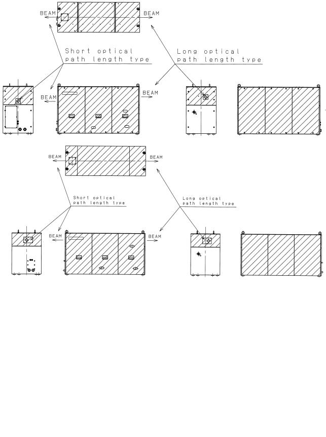
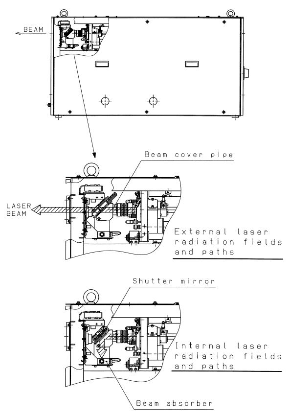
3)Position of laser beam emission
Fig.2.1(a) is the position of panel that laser beam exposure is occurred without panel in C1000-E, when your maintenance. Fig.2.1(b) is the position of panel that laser beam exposure is occurred without panel in C2000-E, when your maintenance. Fig.2.1(c) is the position of panel that laser beam exposure is occurred without panel in C4000-E, when your maintenance. Fig.2.1(d) is the position of laser beam delivery in C1000-E. Fig.2.1(e) is the position of laser beam delivery in C2000-E. Fig.2.1(f) is the position of laser beam delivery in C4000-E.
- 8 -
B-70315EN/01 |
2.SAFETY |
Fig.2.1(a) Laser beam exposure position without panel as operating (C1000-E)
Fig.2.1(b) Laser beam exposure position without panel as operating (C2000-E)
Fig.2.1(c) Laser beam exposure position without panel as operating (C4000-E)
- 9 -
2.SAFETY |
B-70315EN/01 |
Fig.2.1(d) The position of laser beam delivery (C1000-E)
- 10 -

B-70315EN/01 |
2.SAFETY |
Fig.2.1(e) The position of laser beam delivery (C2000-E)
Fig.2.1(f) The position of laser beam delivery (C4000-E)
- 11 -

2.SAFETY |
B-70315EN/01 |
2.2 HIGH VOLTAGE
1)Potential hazards
There is RF voltage of 3 to 4kVo-p in the cabinet of the laser oscillator.
There is 200 VAC power in the relay panel, be careful not to touch the high voltage.
2)Safety recommendations
When it checks the oscillator and exchange the unit, intercept a main breaker of the oscillator and the power supply. Lock the breaker to prevent misconnection and display the sign while working.
Install safety cover after unit replacement or cable connection. Unless safety cover is installed, never perform operation. Follow standard industrial safety practices for working with high voltage.
EXAMPLES
•Do not work on the laser oscillator if you are tired or have taken medicine.
•Do not wear anything metal, like a ring, bracelet, watch, belt buckle, earrings, or keys.
•They might contact high voltage.
•Never stand on a wet surface.
•Do not touch electrical components in the cabinets with both hands at once. Keep one hand in a pocket.
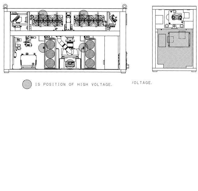
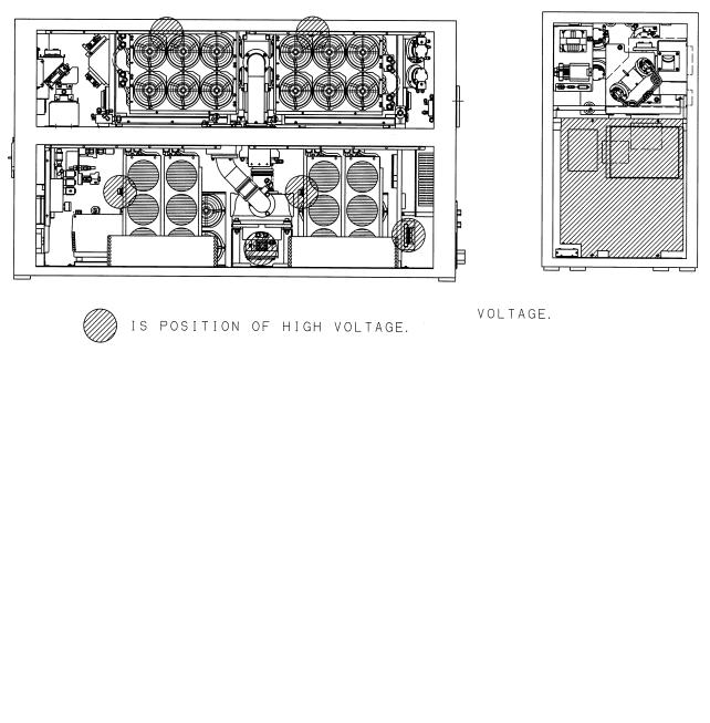
3)Position of high voltage
Fig.2.2(a) is the position of high voltage in C1000-E (Front, maintenance side).
Fig.2.2(b)is the position of high voltage in C1000-E (Back side). Fig.2.2(c) is the position of high voltage in C2000-E (Front, maintenance side).
Fig.2.2(d)is the position of high voltage in C2000-E (Back side). Fig.2.2(e) is the position of high voltage in C4000-E (Front, maintenance side).
Fig.2.2(f) is the position of high voltage in C4000-E (Back side).
- 12 -
B-70315EN/01 |
2.SAFETY |
Fig.2.2(a) Position of high voltage in C1000-E (Front, maintenance side)
Fig.2.2(b) Position of high voltage in C1000-E (Back side)
- 13 -
2.SAFETY |
B-70315EN/01 |
Fig.2.2(c) Position of high voltage in C2000-E (Front, maintenance side)
Fig.2.2(d) Position of high voltage in C2000-E (Back side)
- 14 -
B-70315EN/01 |
2.SAFETY |
Fig.2.2(e) Position of high voltage in C4000-E (Front, maintenance side)
Fig.2.2(f) Position of high voltage in C4000-E (Back side)
- 15 -

2.SAFETY |
B-70315EN/01 |
2.3 SAFETY ENCLOSURE (AT YOUR WORK STATION)
1)Potential hazards
CO2 beam is delivery from oscillator. Direct or scattered beam is exposed.
2)Safety recommendations
Mount the safety enclosure made of acrylic resin which can absorb the laser beam around the working environment.
Mount the interlock switch on the safety enclosure door which extinguishes the laser beam output when the door is open. Never perform operation without safety cover of laser machine.
- 16 -

B-70315EN/01 |
2.SAFETY |
2.4 FIRE
1)Potential hazards
When you work with the laser oscillator or machine, hot
fragments or slag can scatter from your workpiece. The CO2 beam or a reflection of it could ignite flammable material.
2)Safety recommendations
The direct or scattered laser beam can ignite flammable materials such as paper, cloth, and wood. Provide a beam absorber behind the workpiece and around it during maintenance. The absorber can be anodized aluminum, graphite or brick.Put a shield
between yourself and the workpiece when the CO2 beam is on. Even diffuse reflections can harm eyes and skin and may ignite flammable material.
- 17 -

2.SAFETY |
B-70315EN/01 |
2.5 TOXIC FUME
1)Potential hazards
Some materials such as certain plastics can emit toxic fume when they burn under the laser beam.
2)Safety recommendations
Install the exhaust system to remove toxic fume from the work environment.
Consult the manufacturer of the material you are processing to learn if it creates any fumes when heated or burned.
- 18 -

B-70315EN/01 |
2.SAFETY |
2.6 HIGH TEMPERATURE
1)Potential hazards
When you touch a part of high temperature, your skin burn.
2)Safety recommendations
The pipes of the gas circular system are very a high temperature. Do not touch pipes, heat exchanger and turbo blower because it does not do the burn. It is hot immediately after having stopped driving. After getting cold enough in case of removing, dismount it.
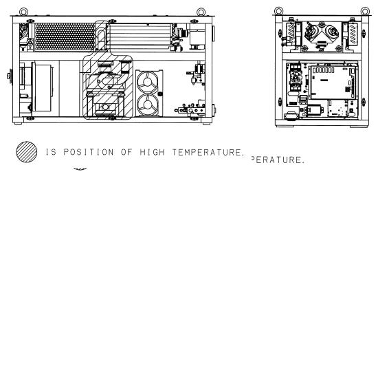
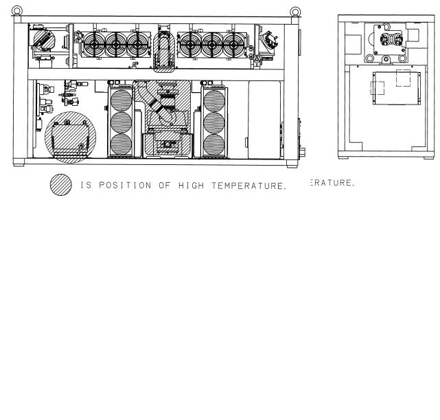
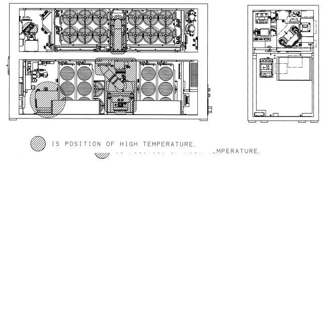
3)Position of high temperature
Fig.2.6(a) is the position of high temperature in C1000-E (Front, maintenance side).
Fig.2.6(b) is the position of high temperature in C1000-E (Back side).
Fig.2.6(c) is the position of high temperature in C2000-E (Front, maintenance side).
Fig.2.6(d) is the position of high temperature in C2000-E (Back side).
Fig.2.6(e) is the position of high temperature in C4000-E (Front, maintenance side).
Fig.2.6(f) is the position of high temperature in C4000-E (Back side).
- 19 -
2.SAFETY |
B-70315EN/01 |
Fig.2.6(a) Position of high temperature in C1000-E (Front, maintenance side).
Fig.2.6(b) Position of high temperature in C1000-E (Back side).
- 20 -
B-70315EN/01 |
2.SAFETY |
Fig.2.6(c) Position of high temperature in C2000-E (Front, maintenance side).
Fig.2.6(d) Position of high temperature in C2000-E (Back side).
- 21 -
2.SAFETY |
B-70315EN/01 |
Fig.2.6(e) Position of high temperature in C4000-E (Front, maintenance side).
Fig.2.6(f) Position of high temperature in C4000-E (Back side).
- 22 -
Loading...