


 Loading...
GE Fanuc Automation
Computer Numerical Control Products
Series 21 / 210 – Model B
Maintenance Manual
GFZ-62705EN/03 |
October 1997 |
GFL-001
Warnings, Cautions, and Notes as Used in this Publication
Warning
Warning notices are used in this publication to emphasize that hazardous voltages, currents, temperatures, or other conditions that could cause personal injury exist in this equipment or may be associated with its use.
In situations where inattention could cause either personal injury or damage to equipment, a Warning notice is used.
Caution
Caution notices are used where equipment might be damaged if care is not taken.
Note
Notes merely call attention to information that is especially significant to understanding and operating the equipment.
This document is based on information available at the time of its publication. While efforts have been made to be accurate, the information contained herein does not purport to cover all details or variations in hardware or software, nor to provide for every possible contingency in connection with installation, operation, or maintenance. Features may be described herein which are not present in all hardware and software systems. GE Fanuc Automation assumes no obligation of notice to holders of this document with respect to changes subsequently made.
GE Fanuc Automation makes no representation or warranty, expressed, implied, or statutory with respect to, and assumes no responsibility for the accuracy, completeness, sufficiency, or usefulness of the information contained herein. No warranties of merchantability or fitness for purpose shall apply.
PowerMotion is a trademark of GE Fanuc Automation North America, Inc.
©Copyright 1997 GE Fanuc Automation North America, Inc.
All Rights Reserved.

SAFETY PRECAUTIONS
This section describes the safety precautions related to the use of CNC units. It is essential that these precautions be observed by users to ensure the safe operation of machines equipped with a CNC unit (all descriptions in this section assume this configuration).
CNC maintenance involves various dangers. CNC maintenance must be undertaken only by a qualified technician.
Users must also observe the safety precautions related to the machine, as described in the relevant manual supplied by the machine tool builder.
Before checking the operation of the machine, take time to become familiar with the manuals provided by the machine tool builder and FANUC.
Contents
1. DEFINITION OF WARNING, CAUTION, AND NOTE . . . . . . . . . . . . . . . . . . . . . . . . s±2
2. WARNINGS, CAUTIONS, AND NOTES RELATED TO CHECK OPERATION . . s±3
3. WARNINGS AND NOTES RELATED TO REPLACEMENT . . . . . . . . . . . . . . . . . . s±4
4. WARNINGS AND NOTES RELATED TO PARAMETERS . . . . . . . . . . . . . . . . . . . . s±5
5. WARNINGS RELATED TO DAILY MAINTENANCE . . . . . . . . . . . . . . . . . . . . . . . . . s±6
s±1

SAFETY PRECAUTIONS B±62705EN/03
1 DEFINITION OF WARNING, CAUTION, AND NOTE
This manual includes safety precautions for protecting the maintenance personnel (herein referred to as the user) and preventing damage to the machine. Precautions are classified into Warnings and Cautions according to their bearing on safety. Also, supplementary information is described as a Note. Read the Warning, Caution, and Note thoroughly before attempting to use the machine.
WARNING
Applied when there is a danger of the user being injured or when there is a damage of both the user being injured and the equipment being damaged if the approved procedure is not observed.
CAUTION
Applied when there is a danger of the equipment being damaged, if the approved procedure is not observed.
NOTE
The Note is used to indicate supplementary information other than Warning and Caution.
Read this manual carefully, and store it in a safe place.
s±2

B±62705EN/03 SAFETY PRECAUTIONS
2 WARNINGS, CAUTIONS, AND NOTES RELATED TO CHECK OPERATION
WARNING
1.When checking the operation of the machine with the cover removed
(1)The user's clothing could become caught in the spindle or other components, thus presenting a danger of injury. When checking the operation, stand away from the machine to ensure that your clothing does not become tangled in the spindle or other components.
(2)When checking the operation, perform idle operation without workpiece. When a workpiece is mounted in the machine, a malfunction could cause the workpiece to be dropped or destroy the tool tip, possibly scattering fragments throughout the area. This presents a serious danger of injury. Therefore, stand in a safe location when checking the operation.
2.When checking the machine operation with the power magnetics cabinet door opened
(1)The power magnetics cabinet has a high±voltage section (carrying a  mark). Never touch the high±voltage section. The high±voltage section presents a severe risk of electric
shock. Before starting any check of the operation, confirm that the cover is mounted on the high±voltage section. When the high±voltage section itself must be checked, note that touching a terminal presents a severe danger of electric shock.
(2)Within the power magnetics cabinet, internal units present potentially injurious corners and projections. Be careful when working inside the power magnetics cabinet.
3.Never attempt to machine a workpiece without first checking the operation of the machine. Before starting a production run, ensure that the machine is operating correctly by performing a trial run using, for example, the single block, feedrate override, or machine lock function or by operating the machine with neither a tool nor workpiece mounted. Failure to confirm the correct operation of the machine may result in the machine behaving unexpectedly, possibly causing damage to the workpiece and/or machine itself, or injury to the user.
4.Before operating the machine, thoroughly check the entered data.
Operating the machine with incorrectly specified data may result in the machine behaving unexpectedly, possibly causing damage to the workpiece and/or machine itself, or injury to the user.
5.Ensure that the specified feedrate is appropriate for the intended operation. Generally, for each machine, there is a maximum allowable feedrate. The appropriate feedrate varies with the intended operation. Refer to the manual provided with the machine to determine the maximum allowable feedrate. If a machine is run at other than the correct speed, it may behave unexpectedly, possibly causing damage to the workpiece and/or machine itself, or injury to the user.
6.When using a tool compensation function, thoroughly check the direction and amount of compensation. Operating the machine with incorrectly specified data may result in the machine behaving unexpectedly, possibly causing damage to the workpiece and/or machine itself, or injury to the user.
s±3

SAFETY PRECAUTIONS B±62705EN/03
3 WARNINGS AND NOTES RELATED TO REPLACEMENT
WARNING
1.Always turn off the power to the CNC and the main power to the power magnetics cabinet. If only the power to the CNC is turned off, power may continue to be supplied to the serve section. In such a case, replacing a unit may damage the unit, while also presenting a danger of electric shock.
2.When a heavy unit is to be replaced, the task must be undertaken by two persons. If the replacement is attempted by only one person, the replacement unit could slip and fall, possibly causing injury.
3.After the power is turned off, the servo amplifier and spindle amplifier may retain voltages for a while, such that there is a danger of electric shock even while the amplifier is turned off. Allow at least twenty minutes after turning off the power for these residual voltages to dissipate.
4.When replacing a unit, ensure that the new unit has the same parameter and other settings as the old unit. (For details, refer to the manual provided with the machine.) Otherwise, unpredictable machine movement could damage the workpiece or the machine itself, and present a danger of injury.
s±4

B±62705EN/03 SAFETY PRECAUTIONS
4 WARNINGS AND NOTES RELATED TO PARAMETERS
WARNING
1.When machining a workpiece for the first time after modifying a parameter, close the machine cover. Never use the automatic operation function immediately after such a modification. Instead, confirm normal machine operation by using functions such as the single block function, feedrate override function, and machine lock function, or by operating the machine without mounting a tool and workpiece. If the machine is used before confirming that it operates normally, the machine may move unpredictably, possibly damaging the machine or workpiece, and presenting a risk of injury.
2.The CNC and PMC parameters are set to their optimal values, so that those parameters usually need not be modified. When a parameter must be modified for some reason, ensure that you fully understand the function of that parameter before attempting to modify it. If a parameter is set incorrectly, the machine may move unpredictably, possibly damaging the machine or workpiece, and presenting a risk of injury.
s±5

SAFETY PRECAUTIONS B±62705EN/03
5 WARNINGS RELATED TO DAILY MAINTENANCE
WARNING
1. Memory backup battery replacement
When replacing the memory backup batteries, keep the power to the machine (CNC) turned on, and apply an emergency stop to the machine. Because this work is performed with the power on and the cabinet open, only those personnel who have received approved safety and maintenance training may perform this work.
When replacing the batteries, be careful not to touch the high±voltage circuits (marked  and fitted with an insulating cover).
Touching the uncovered high±voltage circuits presents an extremely dangerous electric shock hazard.
NOTE
The CNC uses batteries to preserve the contents of its memory, because it must retain data such as programs, offsets, and parameters even while external power is not applied.
If the battery voltage drops, a low battery voltage alarm is displayed on the machine operator's panel or CRT screen.
When a low battery voltage alarm is displayed, replace the batteries within a week. Otherwise, the contents of the CNC's memory will be lost.
To replace the battery, see the procedure described in Section 2.6 of this manual.
s±6

B±62705EN/03 |
SAFETY PRECAUTIONS |
|
|
WARNING
2. Absolute pulse coder battery replacement
When replacing the memory backup batteries, keep the power to the machine (CNC) turned on, and apply an emergency stop to the machine. Because this work is performed with the power on and the cabinet open, only those personnel who have received approved safety and maintenance training may perform this work.
When replacing the batteries, be careful not to touch the high±voltage circuits (marked  and fitted with an insulating cover).
Touching the uncovered high±voltage circuits presents an extremely dangerous electric shock hazard.
NOTE
The absolute pulse coder uses batteries to preserve its absolute position.
If the battery voltage drops, a low battery voltage alarm is displayed on the machine operator's panel or CRT screen.
When a low battery voltage alarm is displayed, replace the batteries within a week. Otherwise, the absolute position data held by the pulse coder will be lost.
To replace the battery, see the procedure described in Section 2.6 of this manual.
s±7

SAFETY PRECAUTIONS |
B±62705EN/03 |
|
|
WARNING
3. Fuse replacement
Before replacing a blown fuse, however, it is necessary to locate and remove the cause of the blown fuse.
For this reason, only those personnel who have received approved safety and maintenance training may perform this work.
When replacing a fuse with the cabinet open, be careful not to touch the high±voltage circuits (marked  and fitted with an insulating cover).
Touching an uncovered high±voltage circuit presents an extremely dangerous electric shock hazard.
s±8
B±62705EN/03 |
PREFACE |
|
|
PREFACE
|
|
|
Description of |
This manual consists of following chapters. |
|
this manual |
1.DISPLAY AND OPERATION |
|
|
||
|
This chapter covers those items, displayed on the screen, that are related |
|
|
to maintenance. A list of all supported operations is also provided at the |
|
|
end of this chapter. |
|
|
2.HARDWARE |
|
|
This chapter covers hardware±related items, including the hardware |
|
|
configuration, connection, and NC status indicated on printed circuit |
|
|
boards. A list of all units is also provided as well as an explanation of how |
|
|
to replace each unit. |
|
|
3.INPUT AND OUTPUT OF DATA |
|
|
This chapter describes the input/output of data, including programs, |
|
|
parameters, and tool compensation data, as well as the input/output |
|
|
procedures for conversational data. |
|
|
4.INTERFACE BETWEEN NC AND PMC |
|
|
This chapter describes the PMC specifications, the system configuration, |
|
|
and the signals used by the PMC. |
|
|
5.DIGITAL SERVO |
|
|
This chapter describes the servo tuning screen and how to adjust the |
|
|
reference position return position. |
|
|
6.AC SPINDLE (SERIAL INTERFACE) |
|
|
These chapters describe the spindle amplifier checkpoints, as well as the |
|
|
spindle tuning screen. |
|
|
7.TROUBLESHOOTING |
|
|
This chapter describes the procedures to be followed in the event of |
|
|
certain problems occurring, for example, if the power cannot be turned on |
|
|
or if manual operation cannot be performed. Countermeasures to be |
|
|
applied in the event of alarms being output are also described. |
|
|
APPENDIX |
|
|
The appendix consists of a list of all alarms, a list of maintenance parts, |
|
|
and boot system. |
|
|
This manual does not provide a parameter list. If necessary, refer to the |
|
|
separate PARAMETER MANUAL (B±62710EN) . |
|
p±1
|
|
PREFACE |
|
B±62705EN/03 |
||
|
|
|
|
|
|
|
Applicable models |
This manual can be used with the following models. The abbreviated |
|||||
|
|
names may be used. |
|
|
||
|
|
|
|
|
|
|
Product Name |
|
Abbreviations |
Software series (Specification) |
|||
|
|
|
|
|
|
|
FANUC Series 21±MB |
21±MB |
Series 21 |
|
D201(A02B±0179±H800#D201) |
||
|
|
|
|
|||
21±MB |
Series 21 |
M series |
DDA1(A02B±0218±H501#DDA1) |
|||
|
|
|||||
|
|
|
|
|
|
|
FANUC Series 210±MB |
210±MB |
Series 210 |
|
DDA1(A02B±0218±H501#DDA1) |
||
|
|
|
|
|
|
|
|
Control unit A |
21±TB |
Series 21 |
|
DE01(A02B±0210±H501#DE01) |
|
|
(Control unit A) |
|
DE02(A02B±0210±H501#DE02) |
|||
FANUC Series 21±TB |
|
|
|
|||
|
|
|
|
|
||
Control unit B |
21±TB |
Series 21 |
T series |
DEA1(A02B±0219±H501#DEA1) |
||
|
||||||
|
(Control unit B) |
|
||||
|
|
|
|
|
||
|
|
|
|
|
|
|
FANUC Series 210±TB |
Control unit B |
210±TB |
Series 210 |
|
DEA1(A02B±0219±H501#DEA1) |
|
NOTE
Some function described in this manual may not be applied to some products.
For details, refer to the DESCRIPTIONS (B±62702EN).
Related manuals |
The table below lists manuals related to MODEL B of Series 21, Series, |
|||
|
Series 210. |
|
|
|
|
In the table, this manual is marked with an asterisk(*). |
|
|
|
|
Table 1 Related Manuals |
|
|
|
|
|
|
|
|
|
Manual name |
|
Specification |
|
|
|
number |
|
|
|
|
|
|
|
|
|
|
|
|
|
DESCRIPTIONS |
|
B±62702EN |
|
|
|
|
|
|
|
CONNECTION MANUAL (HARDWARE) |
|
B±62703EN |
|
|
|
|
|
|
|
CONNECTION MANUAL (FUNCTION) |
|
B±62703EN±1 |
|
|
|
|
|
|
|
OPERATOR'S MANUAL FOR LATHE |
|
B±62534E |
|
|
|
|
|
|
|
OPERATOR'S MANUAL FOR MACHINING CENTER |
|
B±62704EN |
|
|
|
|
|
|
|
MAINTENANCE MANUAL |
|
B±62705EN |
* |
|
|
|
|
|
|
PARAMETER MANUAL |
|
B±62710EN |
|
|
|
|
|
|
|
MACRO COMPILER/MACRO EXECUTOR |
|
B±61803E±1 |
|
|
PROGRAMMING MANUAL |
|
|
|
|
|
|
|
|
|
FAPT MACRO COMPILER (For Personal Computer) |
|
B±66102E |
|
|
PROGRAMMING MANUAL |
|
|
|
|
|
|
|
|
|
CONVERSATIONAL AUTOMATIC PROGRAMMING FUNCTION |
|
B±61874E±1 |
|
|
FOR MACHINING CENTER OPERATOR'S MANUAL |
|
|
|
|
|
|
|
|
p±2

B±62705EN/03 |
Table of Contents |
SAFETY PRECAUTIONS . . . . . . . . . . . . . . . . . . . . . . . . . . . . . . . . . . . . . . . . . . . . . . . . . . |
s±1 |
||
PREFACE . . . |
. . . . . . . . . . . . . . . . . . . . . . . . . . . . . . . . . . . . . . . . . . . . . . . . . . . . . . . . . . . . . |
p±1 |
|
1. DISPLAY AND OPERATION . . . . . . . . . . . . . . . . . . . . . . . . . . . . . . . . . . . . . . . . . . . . . |
1 |
||
1.1 FUNCTION KEYS AND SOFT KEYS . . . . . . . . . . . . . . . . . . . . . . . . . . . . . . . . . . . . . . . . . . . . . . . . |
2 |
||
|
1.1.1 |
Soft Keys . . . . . . . . . . . . . . . . . . . . . . . . . . . . . . . . . . . . . . . . . . . . . . . . . . . . . . . . . . . . . . . . . . . . . . . . |
2 |
1.2 SCREEN DISPLAYED IMMEDIATELY AFTER POWER IS TURNED ON . . . . . . . . . . . . . . . . . . |
21 |
||
|
1.2.1 |
Loading of Software . . . . . . . . . . . . . . . . . . . . . . . . . . . . . . . . . . . . . . . . . . . . . . . . . . . . . . . . . . . . . . . |
21 |
|
1.2.2 |
System Monitor Screen . . . . . . . . . . . . . . . . . . . . . . . . . . . . . . . . . . . . . . . . . . . . . . . . . . . . . . . . . . . . . |
21 |
|
1.2.3 |
Slot Status Display . . . . . . . . . . . . . . . . . . . . . . . . . . . . . . . . . . . . . . . . . . . . . . . . . . . . . . . . . . . . . . . . |
22 |
|
1.2.4 |
Setting Module Screen . . . . . . . . . . . . . . . . . . . . . . . . . . . . . . . . . . . . . . . . . . . . . . . . . . . . . . . . . . . . . |
23 |
|
1.2.5 |
Configuration Display of Software . . . . . . . . . . . . . . . . . . . . . . . . . . . . . . . . . . . . . . . . . . . . . . . . . . . . |
23 |
1.3 |
SYSTEM CONFIGURATION SCREEN . . . . . . . . . . . . . . . . . . . . . . . . . . . . . . . . . . . . . . . . . . . . . . . |
24 |
|
|
1.3.1 |
Display Method . . . . . . . . . . . . . . . . . . . . . . . . . . . . . . . . . . . . . . . . . . . . . . . . . . . . . . . . . . . . . . . . . . . |
24 |
|
1.3.2 |
Configuration of PCBs . . . . . . . . . . . . . . . . . . . . . . . . . . . . . . . . . . . . . . . . . . . . . . . . . . . . . . . . . . . . . |
24 |
|
1.3.3 |
Software Configuration Screen . . . . . . . . . . . . . . . . . . . . . . . . . . . . . . . . . . . . . . . . . . . . . . . . . . . . . . . |
25 |
|
1.3.4 |
Module Configuration Screen . . . . . . . . . . . . . . . . . . . . . . . . . . . . . . . . . . . . . . . . . . . . . . . . . . . . . . . . |
25 |
1.4 |
ALARM HISTORY SCREEN . . . . . . . . . . . . . . . . . . . . . . . . . . . . . . . . . . . . . . . . . . . . . . . . . . . . . . . |
27 |
|
|
1.4.1 |
General . . . . . . . . . . . . . . . . . . . . . . . . . . . . . . . . . . . . . . . . . . . . . . . . . . . . . . . . . . . . . . . . . . . . . . . . . |
27 |
|
1.4.2 |
Screen Display . . . . . . . . . . . . . . . . . . . . . . . . . . . . . . . . . . . . . . . . . . . . . . . . . . . . . . . . . . . . . . . . . . . . |
27 |
|
1.4.3 |
Clearing Alarm History . . . . . . . . . . . . . . . . . . . . . . . . . . . . . . . . . . . . . . . . . . . . . . . . . . . . . . . . . . . . . |
27 |
|
1.4.4 |
Alarm Display . . . . . . . . . . . . . . . . . . . . . . . . . . . . . . . . . . . . . . . . . . . . . . . . . . . . . . . . . . . . . . . . . . . . |
27 |
1.5 EXTERNAL OPERATOR MESSAGES RECORD . . . . . . . . . . . . . . . . . . . . . . . . . . . . . . . . . . . . . . . |
28 |
||
|
1.5.1 |
Screen Display . . . . . . . . . . . . . . . . . . . . . . . . . . . . . . . . . . . . . . . . . . . . . . . . . . . . . . . . . . . . . . . . . . . . |
28 |
|
1.5.2 |
Deletion of External Operator Messages Record . . . . . . . . . . . . . . . . . . . . . . . . . . . . . . . . . . . . . . . . . |
28 |
|
1.5.3 |
Parameter . . . . . . . . . . . . . . . . . . . . . . . . . . . . . . . . . . . . . . . . . . . . . . . . . . . . . . . . . . . . . . . . . . . . . . . . |
29 |
|
1.5.4 |
Notes . . . . . . . . . . . . . . . . . . . . . . . . . . . . . . . . . . . . . . . . . . . . . . . . . . . . . . . . . . . . . . . . . . . . . . . . . . . |
29 |
1.6 |
OPERATION HISTORY . . . . . . . . . . . . . . . . . . . . . . . . . . . . . . . . . . . . . . . . . . . . . . . . . . . . . . . . . . . |
30 |
|
|
1.6.1 |
Parameter Setting . . . . . . . . . . . . . . . . . . . . . . . . . . . . . . . . . . . . . . . . . . . . . . . . . . . . . . . . . . . . . . . . . . |
30 |
|
1.6.2 |
Screen Display . . . . . . . . . . . . . . . . . . . . . . . . . . . . . . . . . . . . . . . . . . . . . . . . . . . . . . . . . . . . . . . . . . . . |
31 |
|
1.6.3 |
Setting The Input Signal or Output Signal to Be Recorded in The Operation History . . . . . . . . . . . . . |
35 |
|
1.6.4 |
Inputting and Outputting the Operation History Data . . . . . . . . . . . . . . . . . . . . . . . . . . . . . . . . . . . . . . |
39 |
|
1.6.5 |
Notes . . . . . . . . . . . . . . . . . . . . . . . . . . . . . . . . . . . . . . . . . . . . . . . . . . . . . . . . . . . . . . . . . . . . . . . . . . . |
43 |
1.7 |
HELP FUNCTION . . . . . . . . . . . . . . . . . . . . . . . . . . . . . . . . . . . . . . . . . . . . . . . . . . . . . . . . . . . . . . . . |
44 |
|
|
1.7.1 |
General . . . . . . . . . . . . . . . . . . . . . . . . . . . . . . . . . . . . . . . . . . . . . . . . . . . . . . . . . . . . . . . . . . . . . . . . . |
44 |
|
1.7.2 |
Display Method . . . . . . . . . . . . . . . . . . . . . . . . . . . . . . . . . . . . . . . . . . . . . . . . . . . . . . . . . . . . . . . . . . . |
44 |
1.8 |
DISPLAYING DIAGNOSTIC PAGE . . . . . . . . . . . . . . . . . . . . . . . . . . . . . . . . . . . . . . . . . . . . . . . . . |
46 |
|
|
1.8.1 |
Displaying Diagnostic Page . . . . . . . . . . . . . . . . . . . . . . . . . . . . . . . . . . . . . . . . . . . . . . . . . . . . . . . . . |
46 |
|
1.8.2 |
Contents Displayed . . . . . . . . . . . . . . . . . . . . . . . . . . . . . . . . . . . . . . . . . . . . . . . . . . . . . . . . . . . . . . . . |
46 |
1.9 |
CNC STATUS DISPLAY . . . . . . . . . . . . . . . . . . . . . . . . . . . . . . . . . . . . . . . . . . . . . . . . . . . . . . . . . . . |
56 |
|
1.10 WAVE FORM DIAGNOSTIC FUNCTION . . . . . . . . . . . . . . . . . . . . . . . . . . . . . . . . . . . . . . . . . . . . |
57 |
||
|
1.10.1 |
Setting Parameters . . . . . . . . . . . . . . . . . . . . . . . . . . . . . . . . . . . . . . . . . . . . . . . . . . . . . . . . . . . . . . . . . |
57 |
|
1.10.2 |
Waveform Diagnostic Parameter Screen . . . . . . . . . . . . . . . . . . . . . . . . . . . . . . . . . . . . . . . . . . . . . . . . |
58 |
|
1.10.3 |
Graphic of Wave Diagnosis data . . . . . . . . . . . . . . . . . . . . . . . . . . . . . . . . . . . . . . . . . . . . . . . . . . . . . . |
61 |
|
1.10.4 |
Data Sampling for Storage Type Waveform Diagnosis . . . . . . . . . . . . . . . . . . . . . . . . . . . . . . . . . . . . . |
63 |
|
1.10.5 |
Outputting Waveform Diagnosis Data (Storage Type) . . . . . . . . . . . . . . . . . . . . . . . . . . . . . . . . . . . . . |
65 |
|
1.10.6 |
Notes . . . . . . . . . . . . . . . . . . . . . . . . . . . . . . . . . . . . . . . . . . . . . . . . . . . . . . . . . . . . . . . . . . . . . . . . . . . |
68 |
1.11 |
OPERATING MONITOR . . . . . . . . . . . . . . . . . . . . . . . . . . . . . . . . . . . . . . . . . . . . . . . . . . . . . . . . . . . |
69 |
|
|
1.11.1 |
Display Method . . . . . . . . . . . . . . . . . . . . . . . . . . . . . . . . . . . . . . . . . . . . . . . . . . . . . . . . . . . . . . . . . . . |
69 |
|
1.11.2 |
Parameters . . . . . . . . . . . . . . . . . . . . . . . . . . . . . . . . . . . . . . . . . . . . . . . . . . . . . . . . . . . . . . . . . . . . . . . |
70 |
1.12 |
LIST OF OPERATIONS . . . . . . . . . . . . . . . . . . . . . . . . . . . . . . . . . . . . . . . . . . . . . . . . . . . . . . . . . . . |
71 |
|
c±1

Table of Contents |
B±62705EN/03 |
|
|
1.13 WARNING SCREEN DISPLAYED WHEN AN OPTION IS CHANGED . . . . . . . . . . . . . . . . . . . . |
76 |
1.14WARNING SCREEN DISPLAYED WHEN SYSTEM SOFTWARE IS REPLACED
(SYSTEM LABEL CHECK ERROR) . . . . . . . . . . . . . . . . . . . . . . . . . . . . . . . . . . . . . . . . . . . . . . . . . |
78 |
|
1.15 POWER MOTION MANAGER . . . . . . . . . . . . . . . . . . . . . . . . . . . . . . . . . . . . . . . . . . . . . . . . . . . . . |
79 |
|
1.15.1 |
Parameter . . . . . . . . . . . . . . . . . . . . . . . . . . . . . . . . . . . . . . . . . . . . . . . . . . . . . . . . . . . . . . . . . . . . . . . . |
79 |
1.15.2 |
Screen Display . . . . . . . . . . . . . . . . . . . . . . . . . . . . . . . . . . . . . . . . . . . . . . . . . . . . . . . . . . . . . . . . . . . . |
80 |
1.15.3 |
Parameter Input/Output . . . . . . . . . . . . . . . . . . . . . . . . . . . . . . . . . . . . . . . . . . . . . . . . . . . . . . . . . . . . . |
87 |
1.15.4 |
Notes . . . . . . . . . . . . . . . . . . . . . . . . . . . . . . . . . . . . . . . . . . . . . . . . . . . . . . . . . . . . . . . . . . . . . . . . . . . |
89 |
1.16 BIOS SETUP OF THE MMC±IV . . . . . . . . . . . . . . . . . . . . . . . . . . . . . . . . . . . . . . . . . . . . . . . . . . . . |
90 |
|
1.16.1 |
BIOS Setup . . . . . . . . . . . . . . . . . . . . . . . . . . . . . . . . . . . . . . . . . . . . . . . . . . . . . . . . . . . . . . . . . . . . . . |
90 |
1.16.2 Keys Used for Operation on the Set±Up Screen . . . . . . . . . . . . . . . . . . . . . . . . . . . . . . . . . . . . . . . . . . |
90 |
|
1.16.3 How to Begin the ªSet±Upº . . . . . . . . . . . . . . . . . . . . . . . . . . . . . . . . . . . . . . . . . . . . . . . . . . . . . . . . . |
91 |
|
1.16.4 How to End the ªSet±Upº . . . . . . . . . . . . . . . . . . . . . . . . . . . . . . . . . . . . . . . . . . . . . . . . . . . . . . . . . . . |
95 |
|
1.17 BIOS SETUP OF INTELLIGENT TERMINALS 1 AND 2 . . . . . . . . . . . . . . . . . . . . . . . . . . . . . . . . |
96 |
|
1.17.1 |
BIOS Setup . . . . . . . . . . . . . . . . . . . . . . . . . . . . . . . . . . . . . . . . . . . . . . . . . . . . . . . . . . . . . . . . . . . . . . |
96 |
1.17.2 Keys Used for Operation on the Set±Up Screen . . . . . . . . . . . . . . . . . . . . . . . . . . . . . . . . . . . . . . . . . . |
96 |
|
1.17.3 How to Begin the Set±Up . . . . . . . . . . . . . . . . . . . . . . . . . . . . . . . . . . . . . . . . . . . . . . . . . . . . . . . . . . . |
97 |
|
1.17.4 Details of the Set±up Items . . . . . . . . . . . . . . . . . . . . . . . . . . . . . . . . . . . . . . . . . . . . . . . . . . . . . . . . . . |
99 |
|
1.17.5 How to End the Set±up . . . . . . . . . . . . . . . . . . . . . . . . . . . . . . . . . . . . . . . . . . . . . . . . . . . . . . . . . . . . . |
102 |
|
2. HARDWARE . . |
. . . . . . . . . . . . . . . . . . . . . . . . . . . . . . . . . . . . . . . . . . . . . . . . . . . . . . . . |
103 |
||
2.1 |
GENERAL OF HANDWARE . . . . . . . . . . . . . . . . . . . . . . . . . . . . . . . . . . . . . . . . . . . . . . . . . . . . . . . |
104 |
||
2.2 CONFIGURATION OF PRINTED CIRCUIT BOARD AND LED DISPLAY . . . . . . . . . . . . . . . . . |
106 |
|||
|
2.2.1 |
Main PCB . . . . . . . . . . . . . . . . . . . . . . . . . . . . . . . . . . . . . . . . . . . . . . . . . . . . . . . . . . . . . . . . . . . . . . . |
106 |
|
|
2.2.2 |
I/O Printed Circuit Board . . . . . . . . . . . . . . . . . . . . . . . . . . . . . . . . . . . . . . . . . . . . . . . . . . . . . . . . . . . |
113 |
|
|
2.2.3 |
Power Supply Printed Circuit Board . . . . . . . . . . . . . . . . . . . . . . . . . . . . . . . . . . . . . . . . . . . . . . . . . . . |
116 |
|
|
2.2.4 |
Option 1 Board . . . . . . . . . . . . . . . . . . . . . . . . . . . . . . . . . . . . . . . . . . . . . . . . . . . . . . . . . . . . . . . . . . . |
117 |
|
|
2.2.5 |
Loader Control Board . . . . . . . . . . . . . . . . . . . . . . . . . . . . . . . . . . . . . . . . . . . . . . . . . . . . . . . . . . . . . . |
118 |
|
|
2.2.6 |
HSSB Interface Board . . . . . . . . . . . . . . . . . . . . . . . . . . . . . . . . . . . . . . . . . . . . . . . . . . . . . . . . . . . . . . |
120 |
|
|
|
2.2.6.1 |
Parts layout . . . . . . . . . . . . . . . . . . . . . . . . . . . . . . . . . . . . . . . . . . . . . . . . . . . . . . . . . . . . . . . |
120 |
|
|
2.2.6.2 |
System block diagram . . . . . . . . . . . . . . . . . . . . . . . . . . . . . . . . . . . . . . . . . . . . . . . . . . . . . . . |
121 |
|
|
2.2.6.3 |
Configuration switch . . . . . . . . . . . . . . . . . . . . . . . . . . . . . . . . . . . . . . . . . . . . . . . . . . . . . . . . |
121 |
|
|
2.2.6.4 |
LED display . . . . . . . . . . . . . . . . . . . . . . . . . . . . . . . . . . . . . . . . . . . . . . . . . . . . . . . . . . . . . . |
122 |
|
2.2.7 |
MMC±IV PCB . . . . . . . . . . . . . . . . . . . . . . . . . . . . . . . . . . . . . . . . . . . . . . . . . . . . . . . . . . . . . . . . . . . . |
123 |
|
|
|
2.2.7.1 |
A02B±0207±C020, A02B±0207±C021, A02B±0207±C022 . . . . . . . . . . . . . . . . . . . . . . . . . |
123 |
|
|
2.2.7.2 |
A16B±2203±0180 . . . . . . . . . . . . . . . . . . . . . . . . . . . . . . . . . . . . . . . . . . . . . . . . . . . . . . . . . . |
129 |
|
2.2.8 |
Intelligent Terminal . . . . . . . . . . . . . . . . . . . . . . . . . . . . . . . . . . . . . . . . . . . . . . . . . . . . . . . . . . . . . . . . |
132 |
|
|
2.2.9 |
Intelligent Terminal 2 . . . . . . . . . . . . . . . . . . . . . . . . . . . . . . . . . . . . . . . . . . . . . . . . . . . . . . . . . . . . . . |
137 |
|
2.3 LIST OF UNIT AND PRINTED CIRCUIT BOARD . . . . . . . . . . . . . . . . . . . . . . . . . . . . . . . . . . . . . |
142 |
|||
|
2.3.1 |
Control Unit P.C.B. . . . . . . . . . . . . . . . . . . . . . . . . . . . . . . . . . . . . . . . . . . . . . . . . . . . . . . . . . . . . . . . . |
142 |
|
|
2.3.2 |
Others |
. . . . . . . . . . . . . . . . . . . . . . . . . . . . . . . . . . . . . . . . . . . . . . . . . . . . . . . . . . . . . . . . . . . . . . . . . . |
144 |
2.4 HOW TO REPLACE THE MODULES . . . . . . . . . . . . . . . . . . . . . . . . . . . . . . . . . . . . . . . . . . . . . . . . |
146 |
|||
|
2.4.1 |
Removing . . . . . . . . . . . . . . . . . . . . . . . . . . . . . . . . . . . . . . . . . . . . . . . . . . . . . . . . . . . . . . . . . . . . . . . |
146 |
|
|
2.4.2 |
Insertion . . . . . . . . . . . . . . . . . . . . . . . . . . . . . . . . . . . . . . . . . . . . . . . . . . . . . . . . . . . . . . . . . . . . . . . . . |
146 |
|
2.5 |
REPLACING THE FUSES . . . . . . . . . . . . . . . . . . . . . . . . . . . . . . . . . . . . . . . . . . . . . . . . . . . . . . . . . |
147 |
||
|
2.5.1 |
Replacing the Fuses for Power Supply of Control Unit . . . . . . . . . . . . . . . . . . . . . . . . . . . . . . . . . . . . |
147 |
|
|
2.5.2 |
Replacing the Fuses for New MMC±IV . . . . . . . . . . . . . . . . . . . . . . . . . . . . . . . . . . . . . . . . . . . . . . . . |
147 |
|
|
2.5.3 |
Replacing the Fuses for Intelligent Terminal 2 . . . . . . . . . . . . . . . . . . . . . . . . . . . . . . . . . . . . . . . . . . . |
148 |
|
|
2.5.4 |
Replacing the Fuse for LCD . . . . . . . . . . . . . . . . . . . . . . . . . . . . . . . . . . . . . . . . . . . . . . . . . . . . . . . . . |
149 |
|
2.6 HOW TO REPLACE THE BATTERIES . . . . . . . . . . . . . . . . . . . . . . . . . . . . . . . . . . . . . . . . . . . . . . . |
150 |
|||
|
2.6.1 |
Replace the Battery for Memory Back Up . . . . . . . . . . . . . . . . . . . . . . . . . . . . . . . . . . . . . . . . . . . . . . |
150 |
|
|
2.6.2 |
Replacing Batteries for Separate Absolute Pulse Coder . . . . . . . . . . . . . . . . . . . . . . . . . . . . . . . . . . . . |
152 |
|
c±2

B±62705EN/03 |
Table of Contents |
|
|
2.6.3 |
Replacing Batteries for Absolute Pulse Coder (α series servo amplifier module) . . . . . . . . . . . . . . . . |
152 |
2.6.4 |
Replacing the Battery for New MMC±IV . . . . . . . . . . . . . . . . . . . . . . . . . . . . . . . . . . . . . . . . . . . . . . . |
154 |
2.6.5 |
Replacing the Battery for Intelligent Terminal . . . . . . . . . . . . . . . . . . . . . . . . . . . . . . . . . . . . . . . . . . . |
155 |
2.7 REPLACING THE FAN MOTOR . . . . . . . . . . . . . . . . . . . . . . . . . . . . . . . . . . . . . . . . . . . . . . . . . . . . |
156 |
||
|
2.7.1 |
Replacing the Fan Motor for Control Unit . . . . . . . . . . . . . . . . . . . . . . . . . . . . . . . . . . . . . . . . . . . . . . |
156 |
|
2.7.2 |
Replacing the Fan for Intelligent Terminal . . . . . . . . . . . . . . . . . . . . . . . . . . . . . . . . . . . . . . . . . . . . . . |
157 |
2.8 REPLACING THE LCD BACKLIGHT FOR DISPLAY . . . . . . . . . . . . . . . . . . . . . . . . . . . . . . . . . . |
158 |
||
2.9 ADJUSTING THE FLAT DISPLAY . . . . . . . . . . . . . . . . . . . . . . . . . . . . . . . . . . . . . . . . . . . . . . . . . . |
161 |
||
|
2.9.1 |
Adjusting the Color Liquid Crystal Display and Plasma Display . . . . . . . . . . . . . . . . . . . . . . . . . . . . . |
161 |
|
2.9.2 |
How to Replace the Monochrome Liquid Crystal Display . . . . . . . . . . . . . . . . . . . . . . . . . . . . . . . . . . |
162 |
2.10 MAINTENANCE OF HEAT PIPE TYPE HEAT EXCHANGER . . . . . . . . . . . . . . . . . . . . . . . . . . . . |
163 |
||
2.11 |
ENVIRONMENTAL REQUIREMENT . . . . . . . . . . . . . . . . . . . . . . . . . . . . . . . . . . . . . . . . . . . . . . . |
166 |
|
2.12 |
POWER SUPPLY . . . . . . . . . . . . . . . . . . . . . . . . . . . . . . . . . . . . . . . . . . . . . . . . . . . . . . . . . . . . . . . . . |
168 |
|
2.13 |
ACTION AGAINST NOISE . . . . . . . . . . . . . . . . . . . . . . . . . . . . . . . . . . . . . . . . . . . . . . . . . . . . . . . . |
170 |
|
|
2.13.1 |
Separating Signal Lines . . . . . . . . . . . . . . . . . . . . . . . . . . . . . . . . . . . . . . . . . . . . . . . . . . . . . . . . . . . . . |
170 |
|
2.13.2 |
Ground . . . . . . . . . . . . . . . . . . . . . . . . . . . . . . . . . . . . . . . . . . . . . . . . . . . . . . . . . . . . . . . . . . . . . . . . . . |
171 |
|
2.13.3 |
Connecting the Signal Ground (SG) of the Control unit . . . . . . . . . . . . . . . . . . . . . . . . . . . . . . . . . . . . |
172 |
|
2.13.4 |
Noise Suppressor . . . . . . . . . . . . . . . . . . . . . . . . . . . . . . . . . . . . . . . . . . . . . . . . . . . . . . . . . . . . . . . . . . |
173 |
|
2.13.5 |
Cable Clamp and Shield Processing . . . . . . . . . . . . . . . . . . . . . . . . . . . . . . . . . . . . . . . . . . . . . . . . . . . |
174 |
3. INPUT AND OUTPUT OF DATA . . . . . . . . . . . . . . . . . . . . . . . . . . . . . . . . . . . . . . . . . |
175 |
|
3.1 SETTING PARAMETERS FOR INPUT/OUTPUT . . . . . . . . . . . . . . . . . . . . . . . . . . . . . . . . . . . . . . |
176 |
|
3.2 INPUTTING/ OUTPUTTING DATA . . . . . . . . . . . . . . . . . . . . . . . . . . . . . . . . . . . . . . . . . . . . . . . . . |
178 |
|
3.2.1 |
Confirming the Parameters Required for Data Output . . . . . . . . . . . . . . . . . . . . . . . . . . . . . . . . . . . . . |
178 |
3.2.2 |
Outputting CNC Parameters . . . . . . . . . . . . . . . . . . . . . . . . . . . . . . . . . . . . . . . . . . . . . . . . . . . . . . . . . |
179 |
3.2.3 |
Outputting PMC Parameters . . . . . . . . . . . . . . . . . . . . . . . . . . . . . . . . . . . . . . . . . . . . . . . . . . . . . . . . . |
180 |
3.2.4 |
Outputting Pitch Error Compensation Amount . . . . . . . . . . . . . . . . . . . . . . . . . . . . . . . . . . . . . . . . . . . |
180 |
3.2.5 |
Outputting Custom Macro Variable Values . . . . . . . . . . . . . . . . . . . . . . . . . . . . . . . . . . . . . . . . . . . . . . |
181 |
3.2.6 |
Outputting Tool Compensation Amount . . . . . . . . . . . . . . . . . . . . . . . . . . . . . . . . . . . . . . . . . . . . . . . . |
181 |
3.2.7 |
Outputting Part Program . . . . . . . . . . . . . . . . . . . . . . . . . . . . . . . . . . . . . . . . . . . . . . . . . . . . . . . . . . . . |
181 |
3.2.8 |
Inputting CNC Parameters . . . . . . . . . . . . . . . . . . . . . . . . . . . . . . . . . . . . . . . . . . . . . . . . . . . . . . . . . . |
182 |
3.2.9 |
Inputting PMC Parameters . . . . . . . . . . . . . . . . . . . . . . . . . . . . . . . . . . . . . . . . . . . . . . . . . . . . . . . . . . |
183 |
3.2.10 |
Inputting Pitch Error Compensation Amount . . . . . . . . . . . . . . . . . . . . . . . . . . . . . . . . . . . . . . . . . . . . |
184 |
3.2.11 |
Inputting Custom Macro Variable Values . . . . . . . . . . . . . . . . . . . . . . . . . . . . . . . . . . . . . . . . . . . . . . . |
184 |
3.2.12 |
Inputting Tool Compensation Amount . . . . . . . . . . . . . . . . . . . . . . . . . . . . . . . . . . . . . . . . . . . . . . . . . |
185 |
3.2.13 |
Inputting Part Programs . . . . . . . . . . . . . . . . . . . . . . . . . . . . . . . . . . . . . . . . . . . . . . . . . . . . . . . . . . . . . |
185 |
3.3 DATA INPUT/OUTPUT ON THE ALL IO SCREEN . . . . . . . . . . . . . . . . . . . . . . . . . . . . . . . . . . . . |
186 |
|
3.3.1 |
Setting Input/Output±Related Parameters . . . . . . . . . . . . . . . . . . . . . . . . . . . . . . . . . . . . . . . . . . . . . . . |
187 |
3.3.2 |
Inputting and Outputting Programs . . . . . . . . . . . . . . . . . . . . . . . . . . . . . . . . . . . . . . . . . . . . . . . . . . . . |
188 |
3.3.3 |
Inputting and Outputting Parameters . . . . . . . . . . . . . . . . . . . . . . . . . . . . . . . . . . . . . . . . . . . . . . . . . . . |
192 |
3.3.4 |
Inputting and Outputting Offset Data . . . . . . . . . . . . . . . . . . . . . . . . . . . . . . . . . . . . . . . . . . . . . . . . . . |
193 |
3.3.5 |
Outputting Custom Macro Common Variables . . . . . . . . . . . . . . . . . . . . . . . . . . . . . . . . . . . . . . . . . . . |
194 |
3.3.6 |
Inputting and Outputting Floppy Files . . . . . . . . . . . . . . . . . . . . . . . . . . . . . . . . . . . . . . . . . . . . . . . . . |
195 |
4. INTERFACE BETWEEN NC AND PMC . . . . . . . . . . . . . . . . . . . . . . . . . . . . . . . . . . . |
200 |
||
4.1 |
GENERAL OF INTERFACE . . . . . . . . . . . . . . . . . . . . . . . . . . . . . . . . . . . . . . . . . . . . . . . . . . . . . . . . |
201 |
|
4.2 |
SPECIFICATION OF PMC . . . . . . . . . . . . . . . . . . . . . . . . . . . . . . . . . . . . . . . . . . . . . . . . . . . . . . . . . |
202 |
|
|
4.2.1 |
Specification . . . . . . . . . . . . . . . . . . . . . . . . . . . . . . . . . . . . . . . . . . . . . . . . . . . . . . . . . . . . . . . . . . . . . |
202 |
|
4.2.2 |
Address . . . . . . . . . . . . . . . . . . . . . . . . . . . . . . . . . . . . . . . . . . . . . . . . . . . . . . . . . . . . . . . . . . . . . . . . . |
203 |
|
4.2.3 |
Address List . . . . . . . . . . . . . . . . . . . . . . . . . . . . . . . . . . . . . . . . . . . . . . . . . . . . . . . . . . . . . . . . . . . . . . |
204 |
|
4.2.4 |
Built±in Debug Function . . . . . . . . . . . . . . . . . . . . . . . . . . . . . . . . . . . . . . . . . . . . . . . . . . . . . . . . . . . . |
216 |
|
4.2.5 System Reserve Area of Internal Relay . . . . . . . . . . . . . . . . . . . . . . . . . . . . . . . . . . . . . . . . . . . . . . . . . |
217 |
|
|
4.2.6 Execution Period of PMC . . . . . . . . . . . . . . . . . . . . . . . . . . . . . . . . . . . . . . . . . . . . . . . . . . . . . . . . . . . |
218 |
|
c±3

Table of Contents |
B±62705EN/03 |
|
|
4.3 |
PMC SCREEN . . . . . . . . . . . . . . . . . . . . . . . . . . . . . . . . . . . . . . . . . . . . . . . . . . . . . . . . . . . . . . . . . . . |
219 |
|
|
4.3.1 |
Display Method . . . . . . . . . . . . . . . . . . . . . . . . . . . . . . . . . . . . . . . . . . . . . . . . . . . . . . . . . . . . . . . . . . . |
219 |
|
4.3.2 |
PMCLAD Screen . . . . . . . . . . . . . . . . . . . . . . . . . . . . . . . . . . . . . . . . . . . . . . . . . . . . . . . . . . . . . . . . . . |
220 |
|
4.3.3 |
PMCDGN Screen . . . . . . . . . . . . . . . . . . . . . . . . . . . . . . . . . . . . . . . . . . . . . . . . . . . . . . . . . . . . . . . . . |
224 |
|
4.3.4 |
Memory Display (M.SRCH) . . . . . . . . . . . . . . . . . . . . . . . . . . . . . . . . . . . . . . . . . . . . . . . . . . . . . . . . . |
228 |
|
4.3.5 |
PMCPRM Screen . . . . . . . . . . . . . . . . . . . . . . . . . . . . . . . . . . . . . . . . . . . . . . . . . . . . . . . . . . . . . . . . . |
232 |
4.4 |
LIST OF SIGNALS BY EACH MODE . . . . . . . . . . . . . . . . . . . . . . . . . . . . . . . . . . . . . . . . . . . . . . . . |
237 |
|
5. DIGITAL SERVO . . . . . . . . . . . . . . . . . . . . . . . . . . . . . . . . . . . . . . . . . . . . . . . . . . . . . . . |
246 |
||
5.1 |
INITIAL SETTING SERVO PARAMETERS . . . . . . . . . . . . . . . . . . . . . . . . . . . . . . . . . . . . . . . . . . . |
247 |
|
5.2 |
SERVO TUNING SCREEN . . . . . . . . . . . . . . . . . . . . . . . . . . . . . . . . . . . . . . . . . . . . . . . . . . . . . . . . . |
250 |
|
|
5.2.1 |
Parameter Setting . . . . . . . . . . . . . . . . . . . . . . . . . . . . . . . . . . . . . . . . . . . . . . . . . . . . . . . . . . . . . . . . . . |
250 |
|
5.2.2 |
Displaying Servo Tuning Screen . . . . . . . . . . . . . . . . . . . . . . . . . . . . . . . . . . . . . . . . . . . . . . . . . . . . . . |
250 |
5.3 |
ADJUSTING REFERENCE POSITION (DOG METHOD) . . . . . . . . . . . . . . . . . . . . . . . . . . . . . . . . |
253 |
|
|
5.3.1 |
General . . . . . . . . . . . . . . . . . . . . . . . . . . . . . . . . . . . . . . . . . . . . . . . . . . . . . . . . . . . . . . . . . . . . . . . . . |
253 |
5.4 |
DOGLESS REFERENCE POSITION SETTING . . . . . . . . . . . . . . . . . . . . . . . . . . . . . . . . . . . . . . . . |
255 |
|
|
5.4.1 |
General . . . . . . . . . . . . . . . . . . . . . . . . . . . . . . . . . . . . . . . . . . . . . . . . . . . . . . . . . . . . . . . . . . . . . . . . . |
255 |
|
5.4.2 |
Operation . . . . . . . . . . . . . . . . . . . . . . . . . . . . . . . . . . . . . . . . . . . . . . . . . . . . . . . . . . . . . . . . . . . . . . . . |
255 |
|
5.4.3 |
Associated Parameters . . . . . . . . . . . . . . . . . . . . . . . . . . . . . . . . . . . . . . . . . . . . . . . . . . . . . . . . . . . . . . |
256 |
6. AC SPINDLE (SERIAL INTERFACE) . . . . . . . . . . . . . . . . . . . . . . . . . . . . . . . . . . . . . |
257 |
||
6.1 AC SPINDLE (SERIAL INTERFACE) . . . . . . . . . . . . . . . . . . . . . . . . . . . . . . . . . . . . . . . . . . . . . . . . |
258 |
||
6.1.1 |
Outline of Spindle Control . . . . . . . . . . . . . . . . . . . . . . . . . . . . . . . . . . . . . . . . . . . . . . . . . . . . . . . . . . |
258 |
|
|
6.1.1.1 Method A of Gear Change for Machining Center . . . . . . . . . . . . . . . . . . . . . . . . . . . . . . . . . |
259 |
|
|
6.1.1.2 Method B of Gear Change for Machining Center(PRM 3705#2=1) . . . . . . . . . . . . . . . . . . . |
259 |
|
|
6.1.1.3 |
For Lathe . . . . . . . . . . . . . . . . . . . . . . . . . . . . . . . . . . . . . . . . . . . . . . . . . . . . . . . . . . . . . . . . . |
259 |
6.1.2 |
Spindle Setting and Tuning Screen . . . . . . . . . . . . . . . . . . . . . . . . . . . . . . . . . . . . . . . . . . . . . . . . . . . . |
260 |
|
|
6.1.2.1 |
Display method . . . . . . . . . . . . . . . . . . . . . . . . . . . . . . . . . . . . . . . . . . . . . . . . . . . . . . . . . . . . |
260 |
|
6.1.2.2 |
Spindle setting screen . . . . . . . . . . . . . . . . . . . . . . . . . . . . . . . . . . . . . . . . . . . . . . . . . . . . . . . |
260 |
|
6.1.2.3 |
Spindle tuning screen . . . . . . . . . . . . . . . . . . . . . . . . . . . . . . . . . . . . . . . . . . . . . . . . . . . . . . . |
261 |
|
6.1.2.4 |
Spindle monitor screen . . . . . . . . . . . . . . . . . . . . . . . . . . . . . . . . . . . . . . . . . . . . . . . . . . . . . . |
263 |
|
6.1.2.5 Correspondence between operation mode and parameters on spindle tuning screen . . . . . . . |
265 |
|
6.1.3 |
Automatic Setting of Standard Parameters . . . . . . . . . . . . . . . . . . . . . . . . . . . . . . . . . . . . . . . . . . . . . . |
267 |
|
6.2 AC SPINDLE (ANALOG INTERFACE) . . . . . . . . . . . . . . . . . . . . . . . . . . . . . . . . . . . . . . . . . . . . . . |
268 |
||
6.2.1 |
Outline of Spindle Control . . . . . . . . . . . . . . . . . . . . . . . . . . . . . . . . . . . . . . . . . . . . . . . . . . . . . . . . . . |
268 |
|
|
6.2.1.1 |
Block diagram . . . . . . . . . . . . . . . . . . . . . . . . . . . . . . . . . . . . . . . . . . . . . . . . . . . . . . . . . . . . . |
268 |
|
6.2.1.2 Calculation of S analog voltage and related parameters . . . . . . . . . . . . . . . . . . . . . . . . . . . . . |
269 |
|
|
6.2.1.3 Tuning S analog voltage (D/A converter) . . . . . . . . . . . . . . . . . . . . . . . . . . . . . . . . . . . . . . . . |
271 |
|
7. TROUBLESHOOTING . . . . . . . . . . . . . . . . . . . . . . . . . . . . . . . . . . . . . . . . . . . . . . . . . . |
272 |
||
7.1 |
CORRECTIVE ACTION FOR FAILURES . . . . . . . . . . . . . . . . . . . . . . . . . . . . . . . . . . . . . . . . . . . . . |
273 |
|
|
7.1.1 |
Investigating the Conditions under which Failure Occurred . . . . . . . . . . . . . . . . . . . . . . . . . . . . . . . . . |
273 |
7.2 |
NO MANUAL OPERATION NOR AUTOMATIC OPERATION CAN BE EXECUTED . . . . . . . . |
275 |
|
7.3 |
JOG OPERATION CANNOT BE DONE . . . . . . . . . . . . . . . . . . . . . . . . . . . . . . . . . . . . . . . . . . . . . . |
279 |
|
7.4 |
HANDLE OPERATION (MPG) CANNOT BE DONE . . . . . . . . . . . . . . . . . . . . . . . . . . . . . . . . . . . . |
282 |
|
7.5 |
AUTOMATIC OPERATION CANNOT BE DONE . . . . . . . . . . . . . . . . . . . . . . . . . . . . . . . . . . . . . . |
284 |
|
7.6 |
CYCLE START LED SIGNAL HAS TURNED OFF . . . . . . . . . . . . . . . . . . . . . . . . . . . . . . . . . . . . . |
291 |
|
7.7 |
NO DISPLAY APPEARS AT POWER±UP . . . . . . . . . . . . . . . . . . . . . . . . . . . . . . . . . . . . . . . . . . . . . |
293 |
|
c±4

B±62705EN/03 |
Table of Contents |
|
|
7.8 |
ALARM 85 TO 87 (READER/PUNCHER INTERFACE ALARM) . . . . . . . . . . . . . . . . . . . . . . . . . |
294 |
7.9 |
ALARM 90 (REFERENCE POSITION RETURN IS ABNORMAL) . . . . . . . . . . . . . . . . . . . . . . . . |
300 |
7.10 |
ALARM 300 (REQUEST FOR REFERENCE POSITION RETURN) . . . . . . . . . . . . . . . . . . . . . . . |
302 |
7.11 |
ALARM 301 TO 305 (ABSOLUTE PULSE CODER IS FAULTY) . . . . . . . . . . . . . . . . . . . . . . . . . . |
303 |
7.12 |
ALARM 306 TO 308 (ABSOLUTE PULSE CODER BATTERY IS LOW) . . . . . . . . . . . . . . . . . . . |
304 |
7.13 |
ALARM 350 (SERIAL A PULSE CODER IS ABNORMAL) . . . . . . . . . . . . . . . . . . . . . . . . . . . . . . |
305 |
7.14 |
ALARM 351 (SERIAL A PULSE CODER COMMUNICATION IS ABNORMAL) . . . . . . . . . . . . |
306 |
7.15 |
ALARM 400 (OVERLOAD) . . . . . . . . . . . . . . . . . . . . . . . . . . . . . . . . . . . . . . . . . . . . . . . . . . . . . . . . |
307 |
7.16 |
ALARM 401 (*DRDY SIGNAL TURNED OFF) . . . . . . . . . . . . . . . . . . . . . . . . . . . . . . . . . . . . . . . . |
309 |
7.17 |
ALARM 404 AND 405 (*DRDY SIGNAL TURNED ON) . . . . . . . . . . . . . . . . . . . . . . . . . . . . . . . . |
310 |
7.18 |
ALARM 410 (EXCESSIVE POSITION ERROR AMOUNT DURING STOP) . . . . . . . . . . . . . . . . |
312 |
7.19 |
ALRAM 411 (EXECESSIVE POSITION ERROR DURING MOVE) . . . . . . . . . . . . . . . . . . . . . . . . |
313 |
7.20 |
ALARM 414 (DIGITAL SERVO SYSTEM IS ABNORMAL) . . . . . . . . . . . . . . . . . . . . . . . . . . . . . |
315 |
7.21 |
ALRAM 416 (DISCONNECTION ALARM) . . . . . . . . . . . . . . . . . . . . . . . . . . . . . . . . . . . . . . . . . . . |
316 |
7.22 |
ALARM 417 (DIGITAL SERVO SYSTEM IS ABNORMAL) . . . . . . . . . . . . . . . . . . . . . . . . . . . . . |
317 |
7.23 |
ALARM 704 (SPINDLE SPEED FLUCTUATION DETECTION ALARM) . . . . . . . . . . . . . . . . . . |
318 |
7.24 |
ALARM 749 (SERIAL SPINDLE COMMUNICATION ERROR) . . . . . . . . . . . . . . . . . . . . . . . . . . |
319 |
7.25 |
ALARM 750 (SPINDLE SERIAL LINK CANNOT BE STARTED) . . . . . . . . . . . . . . . . . . . . . . . . . |
320 |
7.26 |
ALARM 751, 761 (SPINDLE ALARM) . . . . . . . . . . . . . . . . . . . . . . . . . . . . . . . . . . . . . . . . . . . . . . . |
322 |
7.27 |
ALARM 700 (OVERHEAT AT CONTROL SIDE) . . . . . . . . . . . . . . . . . . . . . . . . . . . . . . . . . . . . . . . |
323 |
7.28 |
ALARM 900 (ROM PARITY ERROR) . . . . . . . . . . . . . . . . . . . . . . . . . . . . . . . . . . . . . . . . . . . . . . . . |
324 |
7.29 |
ALARM 910 TO 913 (RAM PARITY) . . . . . . . . . . . . . . . . . . . . . . . . . . . . . . . . . . . . . . . . . . . . . . . . |
325 |
7.30 |
ALARM 920 AND 921 (WATCH DOG OR RAM PARITY) . . . . . . . . . . . . . . . . . . . . . . . . . . . . . . . |
326 |
7.31 |
ALARM 924 (SERVO MODULE MOUNTING ERROR) . . . . . . . . . . . . . . . . . . . . . . . . . . . . . . . . . |
328 |
7.32 |
ALARM 930 (CPU ERROR) . . . . . . . . . . . . . . . . . . . . . . . . . . . . . . . . . . . . . . . . . . . . . . . . . . . . . . . . |
329 |
7.33 |
ALARM 950 (PMC SYSTEM ALARM) . . . . . . . . . . . . . . . . . . . . . . . . . . . . . . . . . . . . . . . . . . . . . . . |
330 |
7.34 |
ALARM 970 (NMI ALARM IN PMC CONTROL MODULE) . . . . . . . . . . . . . . . . . . . . . . . . . . . . . |
331 |
7.35 |
ALARM 971 (NMI ALARM IN SLC) . . . . . . . . . . . . . . . . . . . . . . . . . . . . . . . . . . . . . . . . . . . . . . . . . |
332 |
7.36 |
ALARM 972 (NMI ALARM) . . . . . . . . . . . . . . . . . . . . . . . . . . . . . . . . . . . . . . . . . . . . . . . . . . . . . . . |
333 |
7.37 |
ALARM 973 (NMI ALARM BY UNKNOWN CAUSE) . . . . . . . . . . . . . . . . . . . . . . . . . . . . . . . . . . |
334 |
APPENDIX |
|
|
A. ALARM LIST . . . . . . . . . . . . . . . . . . . . . . . . . . . . . . . . . . . . . . . . . . . . . . . . . . . . . . . . . . |
337 |
|
A.1 |
LIST OF ALARM CODES . . . . . . . . . . . . . . . . . . . . . . . . . . . . . . . . . . . . . . . . . . . . . . . . . . . . . . . . . |
338 |
A.2 |
LIST OF ALARMS (PMC) . . . . . . . . . . . . . . . . . . . . . . . . . . . . . . . . . . . . . . . . . . . . . . . . . . . . . . . . . |
356 |
A.3 |
SPINDLE ALARMS (SERIAL SPINDLE) . . . . . . . . . . . . . . . . . . . . . . . . . . . . . . . . . . . . . . . . . . . . . |
361 |
B. LIST OF MAINTENANCE PARTS . . . . . . . . . . . . . . . . . . . . . . . . . . . . . . . . . . . . . . . . |
366 |
|
C. BOOT SYSTEM . . . . . . . . . . . . . . . . . . . . . . . . . . . . . . . . . . . . . . . . . . . . . . . . . . . . . . . . |
368 |
|
C.1 |
OVERVIEW . . . . . . . . . . . . . . . . . . . . . . . . . . . . . . . . . . . . . . . . . . . . . . . . . . . . . . . . . . . . . . . . . . . . . |
369 |
C.2 |
STARTING AND EXITING FROM THE SYSTEM MONITOR . . . . . . . . . . . . . . . . . . . . . . . . . . . . |
370 |
|
C.2.1 Starting the System Monitor . . . . . . . . . . . . . . . . . . . . . . . . . . . . . . . . . . . . . . . . . . . . . . . . . . . . . . . . . |
370 |
c±5

Table of Contents |
B±62705EN/03 |
|
|
|
C.2.2 |
Exiting from the System Monitor (Activating the CNC) . . . . . . . . . . . . . . . . . . . . . . . . . . . . . . . . . . . |
371 |
C.3 |
SYSTEM MONITOR FUNCTIONS . . . . . . . . . . . . . . . . . . . . . . . . . . . . . . . . . . . . . . . . . . . . . . . . . . |
372 |
|
|
C.3.1 |
Loading a File from a Memory Card into Flash Memory (SYSTEM DATA LOADING Screen) . . . . |
372 |
|
C.3.2 |
Listing the Names of the Files Stored in Flash Memory (SYSTEM DATA CHECK Screen) . . . . . . . |
374 |
|
C.3.3 |
Deleting a File from Flash Memory (SYSTEM DATA DELETE Screen) . . . . . . . . . . . . . . . . . . . . . . |
375 |
|
C.3.4 |
Outputting a File, Stored in Flash Memory, to a Memory Card (SYSTEM DATA SAVE Screen) . . . |
376 |
|
C.3.5 |
Backing up SRAM Data to a Memory Card and Subsequently Restoring Data from a Memory Card |
|
|
|
(SRAM DATA BACKUP Screen) . . . . . . . . . . . . . . . . . . . . . . . . . . . . . . . . . . . . . . . . . . . . . . . . . . . . . |
378 |
|
C.3.6 |
Deleting a File from a Memory Card (MEMORY CARD FILE DELETE Screen) . . . . . . . . . . . . . . . |
380 |
|
C.3.7 |
Formatting a Memory Card . . . . . . . . . . . . . . . . . . . . . . . . . . . . . . . . . . . . . . . . . . . . . . . . . . . . . . . . . . |
381 |
C.4 ERROR MESSAGES AND CORRESPONDING CORRECTIVE ACTIONS . . . . . . . . . . . . . . . . . . |
382 |
||
D. MEMORY CARD OPERATOR'S MANUAL . . . . . . . . . . . . . . . . . . . . . . . . . . . . . . . . |
384 |
||
D.1 |
OUTLINE . . . . . . . . . . . . . . . . . . . . . . . . . . . . . . . . . . . . . . . . . . . . . . . . . . . . . . . . . . . . . . . . . . . . . . . |
385 |
|
D.2 DISTINCTION OF SUPPORTED CARD AND UNSUPPORTED CARD . . . . . . . . . . . . . . . . . . . . |
386 |
||
D.3 |
RESTRICTIONS . . . . . . . . . . . . . . . . . . . . . . . . . . . . . . . . . . . . . . . . . . . . . . . . . . . . . . . . . . . . . . . . . |
387 |
|
|
D.3.1 |
Standard of Memory Card . . . . . . . . . . . . . . . . . . . . . . . . . . . . . . . . . . . . . . . . . . . . . . . . . . . . . . . . . . . |
387 |
|
D.3.2 |
Kind of Memory Card . . . . . . . . . . . . . . . . . . . . . . . . . . . . . . . . . . . . . . . . . . . . . . . . . . . . . . . . . . . . . . |
387 |
|
D.3.3 |
Method of Format of Memory Card . . . . . . . . . . . . . . . . . . . . . . . . . . . . . . . . . . . . . . . . . . . . . . . . . . . |
388 |
|
D.3.4 |
File Operation in Flash Memory Card . . . . . . . . . . . . . . . . . . . . . . . . . . . . . . . . . . . . . . . . . . . . . . . . . . |
388 |
|
D.3.5 |
The Capacity of Flash Memory Card . . . . . . . . . . . . . . . . . . . . . . . . . . . . . . . . . . . . . . . . . . . . . . . . . . |
388 |
|
D.3.6 |
Notice when Flash Memory Card is Formatted with CardPro . . . . . . . . . . . . . . . . . . . . . . . . . . . . . . . |
388 |
|
D.3.7 |
When Flash Memory Card Formatted with BOOT SYSTEM is Used with Each Company Device . . |
388 |
|
D.3.8 |
When Flash Memory Card Formatted with Each Company Device is Used with BOOT SYSTEM . . |
388 |
|
D.3.9 |
Names and Function of Memory Components . . . . . . . . . . . . . . . . . . . . . . . . . . . . . . . . . . . . . . . . . . . |
389 |
D.4 OPERATING OF MEMORY CARD . . . . . . . . . . . . . . . . . . . . . . . . . . . . . . . . . . . . . . . . . . . . . . . . . . |
390 |
||
|
D.4.1 |
Connection of Memory Card . . . . . . . . . . . . . . . . . . . . . . . . . . . . . . . . . . . . . . . . . . . . . . . . . . . . . . . . . |
390 |
|
D.4.2 |
Disconnection of Memory Card . . . . . . . . . . . . . . . . . . . . . . . . . . . . . . . . . . . . . . . . . . . . . . . . . . . . . . |
390 |
D.5 |
BATTERY CHANGE . . . . . . . . . . . . . . . . . . . . . . . . . . . . . . . . . . . . . . . . . . . . . . . . . . . . . . . . . . . . . . |
391 |
|
|
D.5.1 |
Battery . . . . . . . . . . . . . . . . . . . . . . . . . . . . . . . . . . . . . . . . . . . . . . . . . . . . . . . . . . . . . . . . . . . . . . . . . . |
391 |
|
D.5.2 |
Battery Life . . . . . . . . . . . . . . . . . . . . . . . . . . . . . . . . . . . . . . . . . . . . . . . . . . . . . . . . . . . . . . . . . . . . . . |
391 |
|
D.5.3 |
Procedure of Battery Change . . . . . . . . . . . . . . . . . . . . . . . . . . . . . . . . . . . . . . . . . . . . . . . . . . . . . . . . . |
391 |
c±6

B±62705EN/03 1. DISPLAY AND OPERATION
1 DISPLAY AND OPERATION
This chapter describes how to display various screens by the function keys. The screens used for maintenance are respectively displayed.
1.1 FUNCTION KEYS AND SOFT KEYS . . . . . . . . . . . . . 2 1.2 SCREEN DISPLAYED IMMEDIATELY AFTER
POWER IS TURNED ON . . . . . . . . . . . . . . . . . . . . . . . 21 1.3 SYSTEM CONFIGURATION SCREEN . . . . . . . . . . . 24 1.4 ALARM HISTORY SCREEN . . . . . . . . . . . . . . . . . . . . 27 1.5 EXTERNAL OPERATOR MESSAGES
RECORD . . . . . . . . . . . . . . . . . . . . . . . . . . . . . . . . . . . . 28 1.6 OPERATION HISTORY . . . . . . . . . . . . . . . . . . . . . . . . 30 1.7 HELP FUNCTION . . . . . . . . . . . . . . . . . . . . . . . . . . . . 44 1.8 DISPLAYING DIAGNOSTIC PAGE . . . . . . . . . . . . . . 46 1.9 CNC STATUS DISPLAY . . . . . . . . . . . . . . . . . . . . . . . . 56 1.10 WAVE FORM DIAGNOSTIC FUNCTION . . . . . . . . . 57 1.11 OPERATING MONITOR . . . . . . . . . . . . . . . . . . . . . . . 69 1.12 LIST OF OPERATIONS . . . . . . . . . . . . . . . . . . . . . . . . 71 1.13 WARNING SCREEN DISPLAYED WHEN
AN OPTION IS CHANGED . . . . . . . . . . . . . . . . . . . . . 76 1.14 WARNING SCREEN DISPLAYED
WHEN SYSTEM SOFTWARE IS REPLACED (SYSTEM LABEL CHECK ERROR) . . . . . . . . . . . . . 78
1.15 POWER MOTION MANAGER . . . . . . . . . . . . . . . . . . 79 1.16 BIOS SETUP OF THE MMC±IV . . . . . . . . . . . . . . . . . 90 1.17 BIOS SETUP OF INTELLIGENT
TERMINALS 1 AND 2 . . . . . . . . . . . . . . . . . . . . . . . . . 96
1
1. DISPLAY AND OPERATION |
B±62705EN/03 |
1.1
FUNCTION KEYS AND SOFT KEYS
Operations and soft key display staturs for each function key are described below:
1.1.1
Soft Keys
To display a more detailed screen, press a function key followed by a soft key. Soft keys are also used for actual operations.
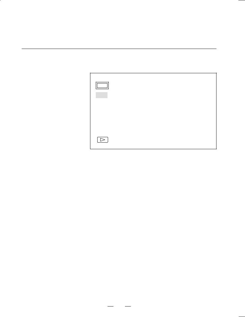
The following illustrates how soft key displays are changed by pressing each function key.
The symbols in the following figures mean as shown below :
: Indicates screens
:Indicates a screen that can be displayed by pressing a function key(*1)
|
|
: |
Indicates a soft key(*2) |
|
|
|
: |
Indicates input from the MDI panel. |
|
|
|
: |
Indicates a soft key displayed in green (or highlighted). |
|
|
|
|
: |
Indicates the continuous menu key (rightmost soft key)(*3). |
|
|
|
||
*1 Press function keys to switch between screens that are used frequently. *2 Some soft keys are not displayed depending on the option configuration.
*3 In some cases, the continuous menu key is omitted when the 12 soft keys type is used.
2
B±62705EN/03 1. DISPLAY AND OPERATION
|
POSITION SCREEN |
|
Soft key transition triggered by the function key POS |
|
|
||
|
|
|
|
|
|
|
|
POS |
|
|
|
|
|
|
|
|
|
|
|
|
|
|
|
|
|
|
|
|
|
|
|
|
|
|
|
|
|
|
|
|
1. |
|||||||||||||||||
|
|
|
|
|
|
|
|
|
|
|
|
|
|
|
|
|
|
|
|
|
|
|
|
|
|
|
|
|
|
|
|
|
|
|
|
|
|
|||||||||||||
|
|
|
|
|
|
|
|
|
|
|
|
|
|
|
|
|
|
|
|
|
|
|
|
|
|
|
|
|
|
|
|
|
|
|
|
|
|
|
|
|
|
|
|
|
|
|||||
|
|
|
|
|
|
|
|
|
|
|
|
|
|
|
|
|
|
|
|
|
|
|
|
|
|
|
|
|
|
|
|
|
|
|
|
|
|
|
|
|
|
|
|
|
|
|
|
|
|
|
|
|
|
|
|
|
Absolute coordinate display |
|
|
|
|
|
|
|
|
|
|
|
|
|
|
|
|
|
|
|
|
|
|
|
|
|
|
||||||||||||||||||
|
|
|
|
|
|
|
|
|
|
|
|
|
|
|
|
|
|
|
|
|
|
|
|
|
|
|
|
|
|
|
|
|
||||||||||||||||||
|
|
|
|
|
|
|
|
|
|
|
|
|
|
|
|
|
|
|
|
|
|
|
|
|
|
|
|
|
|
|
|
|
|
|
|
|
|
|
|
|
|
|
|
|
|
|
|
|
|
|
|
|
|
|
|
|
|
|
|
|
|
|
|
|
|
|
|
|
|
|
|
|
|
|
|
|
|
|
|
|
|
|
|
|
|
|
|
|
|
|
|
|
|
|
|
|
|
|
|
|
|
|
|
|
|
|
|
|
|
|
|
|
|
|
|
|
|
|
|
|
|
|
|
|
|
|
|
|
|
|
|
|
|
|
|
|
|
|
|
|
|
|
|
|
|
|
|
|
|
|
|
|
|
|
|
|
[ABS] |
|
|
|
|
|
|
[(OPRT)] |
|
|
|
[PTSPRE] |
|
|
|
|
|
|
[EXEC] |
|
|
|
|
|
|
|
|
|
|
||||||||||||||||||
|
|
|
|
|
|
|
|
|
|
|
|
|
|
|
|
|
|
|
|
|
|
|
|
|
|
|
|
|||||||||||||||||||||||
|
|
|
|
|
|
|
|
|
|
|
|
|
|
|
|
|
|
|
|
|
|
|
|
|
|
|
|
|
|
|
|
|
|
|
|
|
|
|
|
|
|
|
|
|
|
|
|
|
|
|
|
|
|
|
|
|
|
|
|
|
|
|
|
|
|
|
|
|
|
|
[RUNPRE] |
|
|
|
|
|
|
[EXEC] |
|
|
|
|
|
|
|
|
|
|
|||||||||||||
|
|
|
|
|
|
|
|
|
|
|
|
|
|
|
|
|
|
|
|
|
|
|
|
|
|
|
|
|
|
|
|
|
|
|
||||||||||||||||
|
|
|
|
|
|
|
|
|
|
|
|
|
|
|
|
|
|
|
|
|
|
|
|
|
|
|
|
|
|
|
|
|
|
|
|
|
|
|
|
|
|
|
|
|||||||
|
|
|
|
|
|
|
|
|
|
|
|
|
|
|
|
|
|
|
|
|
|
|
|
|
|
|
|
|
|
|
|
|
|
|
|
|
|
|
|
|
|
|
||||||||
|
|
|
|
|
|
|
|
|
|
|
|
|
|
|
|
|
|
|
|
|
|
|
|
|
|
|
|
|
|
|
|
|
|
|
|
|
|
|
|
|
|
|
|
|
|
|
|
|
|
|
|
|
|
|
|
|
Relative coordinate display |
|
|
|
|
|
|
|
|
|
|
|
|
|
|
|
|
|
|
|
|
|
|
|
|
|
|
|
|||||||||||||||||
|
|
|
|
|
|
|
|
|
|
|
|
|
|
|
|
|
|
|
|
|
|
|
|
|
|
|
|
|
|
|
|
|
||||||||||||||||||
|
|
|
|
|
|
|
|
|
|
|
|
|
|
|
|
|
|
|
|
|
|
|
|
|
|
|
|
|
|
|
|
|
|
|
|
|
|
|
|
|
|
|
|
|||||||
|
|
|
|
|
|
|
|
|
|
|
|
|
|
|
|
|
|
|
|
|
|
|
|
|
|
|
|
|
|
|
|
|
|
|
|
|
|
|
|
|
|
|
|
|
|
|
||||
|
|
|
|
|
|
|
|
|
|
|
|
|
|
|
|
|
|
|
|
(Axis or numeral) |
|
|
|
|
|
|
|
|
|
|
|
|
|
|
|
|||||||||||||||
|
|
|
|
[REL] |
|
|
|
|
|
[(OPRT)] |
|
|
|
[PRESET] |
|
|||||||||||||||||||||||||||||||||||
|
|
|
|
|
|
|
|
|
|
|
|
|
|
|
|
|||||||||||||||||||||||||||||||||||
|
|
|
|
|
|
|
|
|
|
|
|
|
|
|
|
|
|
|
|
[ORIGIN] |
|
|
|
|
|
|
|
|
|
|
|
|
|
|
|
|
|
|
|
|
|
|
|
|
|
|||||
|
|
|
|
|
|
|
|
|
|
|
|
|
|
|
|
|
|
|
|
|
|
|
|
|
|
[ALLEXE] |
|
|
|
|
|
|
||||||||||||||||||
|
|
|
|
|
|
|
|
|
|
|
|
|
|
|
|
|
|
|
|
|
|
|
|
|
|
|
|
|
|
|||||||||||||||||||||
|
|
|
|
|
|
|
|
|
|
|
|
|
|
|
|
|
|
|
|
|
|
|
|
|
|
|
|
|
|
|
|
|
|
|
|
|
|
|
|
|
|
|
|
|
|
|
||||
|
|
|
|
|
|
|
|
|
|
|
|
|
|
|
|
|
|
|
|
|
|
|
|
|
|
|
|
|
|
|
|
|
(Axis name) |
|
[EXEC] |
|
||||||||||||||
|
|
|
|
|
|
|
|
|
|
|
|
|
|
|
|
|
|
|
|
|
|
|
|
|
|
|
|
|
|
|
|
|
|
|||||||||||||||||
|
|
|
|
|
|
|
|
|
|
|
|
|
|
|
|
|
|
|
|
[PTSPRE] |
|
|
|
[EXEC] |
|
|
|
|
|
|
|
|
|
|
||||||||||||||||
|
|
|
|
|
|
|
|
|
|
|
|
|
|
|
|
|
|
|
|
|
|
|
|
|
|
|
|
|
|
|
|
|
||||||||||||||||||
|
|
|
|
|
|
|
|
|
|
|
|
|
|
|
|
|
|
|
|
[RUNPRE] |
|
|
|
[EXEC] |
|
|
|
|
|
|
|
|
|
|
||||||||||||||||
|
|
|
|
|
|
|
|
|
|
|
|
|
|
|
|
|
|
|
|
|
|
|
|
|
|
|
|
|
|
|
|
|
||||||||||||||||||
|
|
|
|
|
|
|
|
|
|
|
|
|
|
|
|
|
|
|
|
|
|
|
|
|
|
|
|
|
|
|
|
|
|
|
|
|
|
|
|
|
|
|
|
|
|
|
|
|
|
|
|
|
|
|
|
|
|
|
|
|
|
|
|
|
|
|
|
|
|
|
|
|
|
|
|
|
|
|
|
|
|
|
|
|
|
|
|
|
|
||||||||||||
|
|
|
|
|
|
|
|
|
|
|
|
|
|
|
|
|
|
|
|
|
|
|
|
|
|
|
|
|
|
|
|
|
|
|
|
|
|
|
|
|
|
|
|
|
|
|
|
|
|
|
|
|
|
|
|
|
Current position display |
|
|
|
|
|
|
|
|
|
|
|
|
|
|
|
|
|
|
|
|
|
|
|
|
|
|
|
|||||||||||||||||
|
|
|
|
|
|
|
|
|
|
|
|
|
|
|
|
|
|
|
|
|
|
|
|
|
|
|
|
|
|
|
|
|
||||||||||||||||||
|
|
|
|
|
|
|
|
|
|
|
|
|
|
|
|
|
|
|
|
|
|
|
|
|
|
|
|
|
|
|
|
|||||||||||||||||||
|
|
|
|
|
|
|
|
|
|
|
|
|
|
|
|
|
|
|
|
|
|
|
|
|
|
|
|
|
|
|
|
|
|
|
|
|
|
|
|
|
|
|
|
|
|
|
|
|
|
|
|
|
|
|
|
|
|
|
|
|
|
|
|
|
|
|
|
|
|
|
|
|
|
|
|
|
|
|
|
|
|
|
|
|
|
|
|
|
|
|
|
|
|
|
|
|
|
|
|
|
|
|
|
|
|
[ALL] |
|
|
|
|
[(OPRT)] |
|
|
|
Axis or numeral |
|
|
[PRESET] |
|
|||||||||||||||||||||||||||||||||
|
|
|
|
|
|
|
|
|
|
|
|
|
|
|||||||||||||||||||||||||||||||||||||
|
|
|
|
|
|
|
|
|
|
|
|
|
|
|
|
|
|
|
|
[ORIGIN] |
|
|
|
|
|
|
|
|
|
|
|
|
|
|
|
|
|
|
|
|
|
|
|
|
|
|||||
|
|
|
|
|
|
|
|
|
|
|
|
|
|
|
|
|
|
|
|
|
|
|
|
[ALLEXE] |
|
|
|
|
|
|
||||||||||||||||||||
|
|
|
|
|
|
|
|
|
|
|
|
|
|
|
|
|
|
|
|
|
|
|
|
|
|
|
|
|
||||||||||||||||||||||
|
|
|
|
|
|
|
|
|
|
|
|
|
|
|
|
|
|
|
|
|
|
|
|
|
|
|
|
|
|
|
|
|
|
|
|
|
|
|
||||||||||||
|
|
|
|
|
|
|
|
|
|
|
|
|
|
|
|
|
|
|
|
|
|
|
|
|
|
|
|
|
|
|
|
|
(Axis name) |
|
[EXEC] |
|
||||||||||||||
|
|
|
|
|
|
|
|
|
|
|
|
|
|
|
|
|
|
|
|
|
|
|
|
|
|
|
|
|
|
|
|
|
|
|
||||||||||||||||
|
|
|
|
|
|
|
|
|
|
|
|
|
|
|
|
|
|
|
|
[PTSPRE] |
|
|
[EXEC] |
|
|
|
|
|
|
|
|
|
|
|
||||||||||||||||
|
|
|
|
|
|
|
|
|
|
|
|
|
|
|
|
|
|
|
|
|
|
|
|
|
|
|
|
|
|
|
|
|||||||||||||||||||
|
|
|
|
|
|
|
|
|
|
|
|
|
|
|
|
|
|
|
|
[RUNPRE] |
|
|
[EXEC] |
|
|
|
|
|
|
|
|
|
|
|||||||||||||||||
|
|
|
|
|
|
|
|
|
|
|
|
|
|
|
|
|
|
|
|
|
|
|
|
|
|
|
|
|
|
|
|
|||||||||||||||||||
|
|
|
|
|
|
|
|
|
|
|
|
|
|
|
|
|
|
|
|
|
|
|
|
|
|
|
|
|
|
|
|
|
|
|
|
|
|
|
|
|
|
|
|
|
|
|
|
|
|
|
|
|
|
|
|
|
|
|
|
|
|
|
|
|
|
|
|
|
|
|
|
|
|
|
|
|
|
|
|
|
|
|
|
|
|
|
|
|
|
|
|
|
|
|
|
|
|
|
|
|
|
|
|
|
|
|
|
Handle interruption |
|
|
|
|
|
|
|
|
|
|
|
|
|
|
|
|
|
|
|
|
|
|
|
|
|
|
|
|
|
|
|
|
|
|||||||||||
|
|
|
|
|
|
|
|
|
|
|
|
|
|
|
|
|
|
|
|
|
|
|
|
|
|
|
|
|
|
|
|
|
|
|
|
|
|
|
||||||||||||
|
|
|
|
|
|
|
|
|
|
|
|
|
|
|
|
|
|
|
|
|
|
|
|
|
|
|
|
|
|
|
|
|
|
|
|
|
||||||||||||||
|
|
|
|
|
|
|
|
|
|
|
|
|
|
|
|
|
|
|
|
|
|
|
|
|
|
|
|
|
|
|
|
|
|
|
|
|
||||||||||||||
|
|
|
|
[HNDL] |
|
|
|
|
|
[(OPRT)] |
|
|
|
|
[PTSPRE] |
|
|
|
|
|
|
|
[EXEC] |
|
|
|
|
|
|
|||||||||||||||||||||
|
|
|
|
|
|
|
|
|
|
|
|
|
|
|
|
|
|
|
|
|
|
|||||||||||||||||||||||||||||
|
|
|
|
|
|
|
|
|
|
|
|
|
|
|
|
|
|
|
|
|
|
|
|
|
|
|
|
|
|
|
|
|
|
|
|
|
|
|
|
|||||||||||
|
|
|
|
|
|
|
|
|
|
|
|
|
|
|
|
|
|
|
|
|
|
[RUNPRE] |
|
|
|
|
|
|
[EXEC] |
|
|
|
|
|
|
|||||||||||||||
|
|
|
|
|
|
|
|
|
|
|
|
|
|
|
|
|
|
|
|
|
|
|
|
|
|
|
|
|
|
|
|
|
|
|||||||||||||||||
|
|
|
|
|
|
|
|
|
|
|
|
|
|
|
|
|
|
|
|
|
|
|
|
|
|
|
|
|
|
|
|
|
|
|
|
|
|
|
|
|
|
|
|
|
||||||
|
|
|
|
|
|
|
|
|
|
|
|
|
|
|
|
|
|
|
|
|
|
|
|
|
|
|
|
|
|
|
|
|
|
|
|
|
|
|
|
|
|
|
|
|
||||||
|
|
|
|
|
|
|
|
|
|
|
|
|
|
|
|
|
|
|
|
|
|
|
|
|
|
|
|
|
|
|
|
|
|
|
|
|
|
|
|
|
||||||||||
|
|
|
|
|
|
|
|
|
|
|
|
|
|
|
|
|
|
|
|
|
|
|
|
|
|
|
|
|
|
|
|
|
|
|
|
|
|
|
|
|
|
|
|
|
|
|
|
|
|
|
|
|
|
|
|
|
Monitor screen |
|
|
|
|
|
|
|
|
|
|
|
|
|
|
|
|
|
|
|
|
|
|
|
|
|
|
|
|
|
|
|
|
|
|||||||||||
|
|
|
|
|
|
|
|
|
|
|
|
|
|
|
|
|
|
|
|
|
|
|
|
|
|
|
|
|
|
|
|
|
|
|
|
|
|
|
||||||||||||
|
|
|
|
|
|
|
|
|
|
|
|
|
|
|
|
|
|
|
|
|
|
|
|
|
|
|
|
|
|
|
|
|||||||||||||||||||
|
|
|
|
|
|
|
|
|
|
|
|
|
|
|
|
|
|
|
|
|
|
|
|
|
|
|
|
|
|
|
|
|||||||||||||||||||
|
|
|
|
[MONI] |
|
|
|
|
[(OPRT)] |
|
|
|
|
|
[PTSPRE] |
|
|
|
|
|
|
[EXEC] |
|
|
|
|
|
|
||||||||||||||||||||||
|
|
|
|
|
|
|
|
|
|
|
|
|
|
|
|
|
|
|
|
|
|
|||||||||||||||||||||||||||||
|
|
|
|
|
|
|
|
|
|
|
|
|
|
|
|
|
|
|
|
|
|
|
|
|
|
|
|
|
|
|
|
|
|
|
|
|
|
|||||||||||||
|
|
|
|
|
|
|
|
|
|
|
|
|
|
|
|
|
|
|
|
|
|
|
[RUNPRE] |
|
|
|
|
|
|
[EXEC] |
|
|
|
|
|
|
||||||||||||||
|
|
|
|
|
|
|
|
|
|
|
|
|
|
|
|
|
|
|
|
|
|
|
|
|
|
|
|
|
|
|
|
|
|
|
||||||||||||||||
|
|
|
|
|
|
|
|
|
|
|
|
|
|
|
|
|
|
|
|
|
|
|
|
|
|
|
|
|
|
|
|
|
|
|
|
|
|
|
|
|
|
|
|
|
|
|
|
|
|
|
3
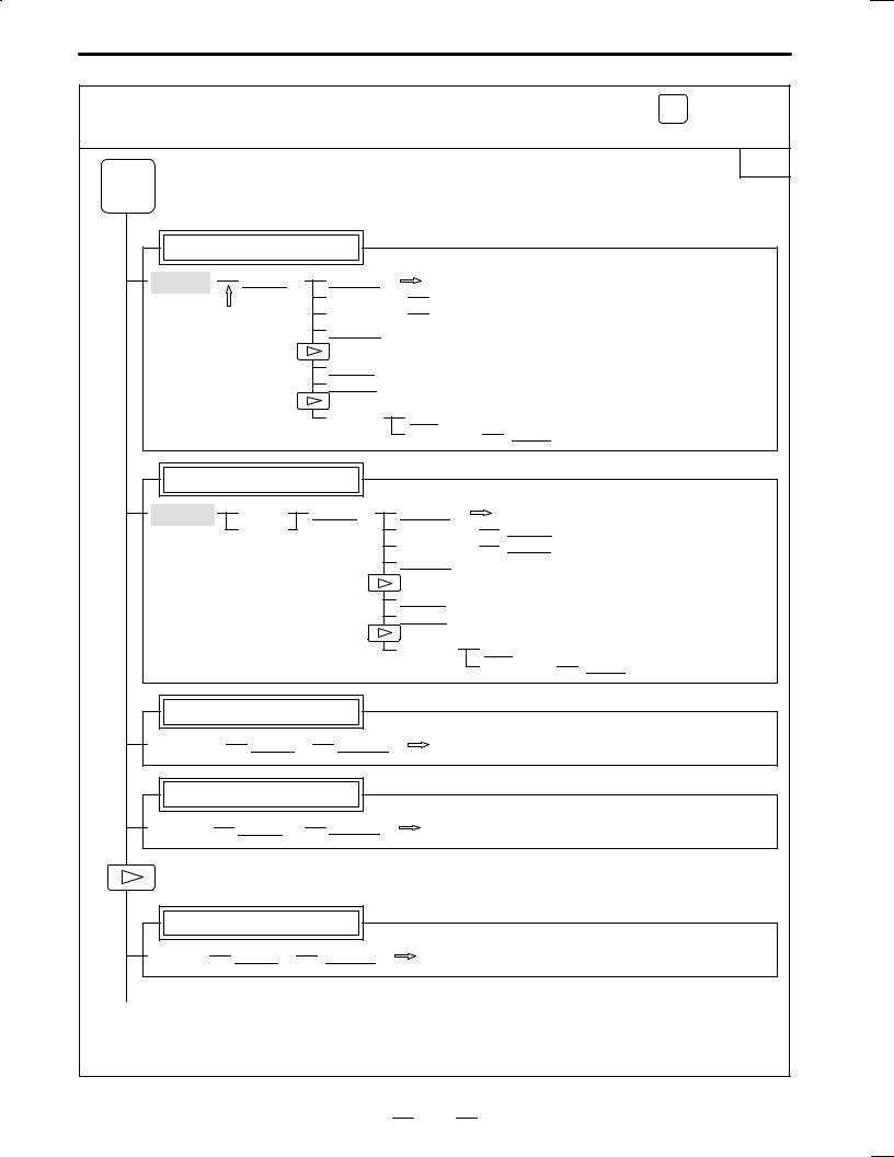
1. DISPLAY AND OPERATION B±62705EN/03
|
PROGRAM SCREEN |
|
Soft key transition triggered by the function key |
PROG |
|
|
|||
|
|
in the MEM mode |
|
|
|
|
|
|
|
|
|
|
|
|
|
|
2. |
|
1/2 |
PROG |
|
|
|
|
Program display screen |
|
|
|
|
[PRGRM] |
[(OPRT)] |
[BG±EDT] |
See ªWhen the soft key [BG±EDT] is pressedº |
|
|
|
(O number) |
[O SRH] |
|
|
(1) |
(N number) |
[N SRH] |
|
|
[REWIND] |
|
|
|
|
|
|
|
|
|
|
[P TYPE] |
|
|
|
|
[Q TYPE] |
|
|
|
|
[F SRH] |
[CAN] |
|
|
|
|
(N number) |
[EXEC] |
Program check display screen |
|
|
|
||
[CHECK] |
[ABS] |
[(OPRT)] |
[BG±EDT] |
See ªWhen the soft key [BG±EDT] is pressedº |
|
|
[REL] |
|
(O number) |
[O SRH] |
|
|
|
|
(N number) |
[N SRH] |
|
|
|
|
[REWIND] |
|
|
|
|
|
[P TYPE] |
|
|
|
|
|
[Q TYPE] |
|
|
|
|
|
[F SRH] |
[CAN] |
|
|
|
|
|
(N number) |
[EXEC] |
Current block display screen |
|
|
|
[CURRNT] |
[(OPRT)] |
[BG±EDT] |
See ªWhen the soft key [BG±EDT] is pressedº |
Next block display screen |
|
|
|
[NEXT] |
[(OPRT)] |
[BG±EDT] |
See ªWhen the soft key [BG±EDT] is pressedº |
Program restart display screen
[RSTR] |
[(OPRT)] |
[BG±EDT] |
See ªWhen the soft key [BG±EDT] is pressedº |
(2)(Continued on the next page)
4

B±62705EN/03 |
1. DISPLAY AND OPERATION |
|
|
2/2
(2)
[FL.SDL] |
|
|
|
[PRGRM] |
|
Return to (1) (Program display) |
|
|
|||||||||||||||||||||||
|
|
|
|
|
|||||||||||||||||||||||||||
|
|
|
|
|
|
|
|
|
|
|
|
|
|
|
|
|
|
|
|
|
|
|
|
|
|
|
|
|
|
|
|
|
|
|
|
|
|
File directory display screen |
|
|
|
|
|
|
|
|
|
|
|
|
|||||||||||||
|
|
|
|
|
|
|
|
|
|
|
|
|
|
|
|
|
|
|
|
|
|
|
|
|
|
|
|
|
|
|
|
|
|
|
|
|
|
|
|
|
|
|
|
|
|
|
|
|
|
|
|
|
|
|
|
|
|
|
|
|
|
||
|
|
|
|
[DIR] |
|
|
[(OPRT)] |
|
|
|
[SELECT] |
|
|
(File No. ) |
|
[F SET] |
|||||||||||||||
|
|
|
|
|
|
|
|
|
|
||||||||||||||||||||||
|
|
|
|
|
|
|
|
|
|
|
|
|
|
|
|
|
|
|
|
|
|
|
[EXEC] |
|
|
||||||
|
|
|
|
|
|
|
|
|
|
|
|
|
|
|
|
|
|
|
|
|
|
|
|
||||||||
|
|
|
|
|
|
|
|
|
|
|
|
|
|
|
|
|
|
|
|
|
|
|
|
|
|
|
|
|
|
|
|
|
|
|
|
|
|
|
|
|
|
|
|
|
|
|
|
|
|
|
|
|
|
|
|
||||||||
|
|
|
|
|
|
|
|
|
|
|
|
|
|
|
|
|
|
|
|
|
|
|
|
|
|
|
|
|
|
|
|
|
|
|
|
|
|
Schedule operation display screen |
|
|
|
|
|
|
|
|
|
|
|
|
|||||||||||||
|
|
|
|
|
|
|
|
|
|
|
|
|
|
|
|
|
|
||||||||||||||
|
|
|
|
|
|
|
|
|
|
|
|
|
|
|
|
|
|
|
|
|
|
|
|
|
|
||||||
|
|
|
|
|
|
|
|
|
|
|
|
|
|
|
|
|
|
|
|
|
|
|
|
||||||||
|
|
|
|
[SCHDUL] |
|
[(OPRT)] |
|
|
|
[CLEAR] |
|
|
|
[CAN] |
|
|
|||||||||||||||
|
|
|
|
|
|
|
|
|
|
|
|||||||||||||||||||||
|
|
|
|
|
|
|
|
|
|
|
|
|
|
|
|
|
|
|
|
|
|
|
|
|
|
|
|
|
|
|
|
|
|
|
|
|
|
|
|
|
|
|
|
|
|
|
|
|
|
|
|
|
|
|
|
|
[EXEC] |
|
|
||||
|
|
|
|
|
|
|
|
|
|
|
|
|
|
|
|
|
|
|
|
|
|
|
|
|
|
||||||
|
|
|
|
|
|
|
|
|
|
|
|
|
|
|
|
|
|
|
|
|
|
|
|||||||||
|
|
|
|
|
|
|
|
|
|
|
|
|
|
|
|
|
|
(Schedule data) |
|
|
[INPUT] |
||||||||||
|
|
|
|
|
|
|
|
|
|
|
|
|
|
|
|
|
|
|
|||||||||||||
|
|
|
|
|
|
|
|
|
|
|
|
|
|
|
|
|
|
|
|
|
|
|
|
|
|
|
|
|
|
|
|
5
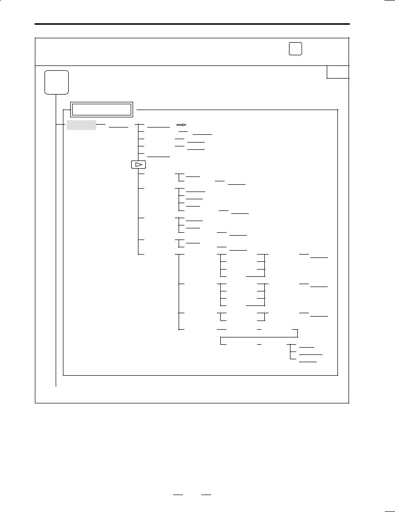
1. DISPLAY AND OPERATION B±62705EN/03
|
PROGRAM SCREEN |
|
Soft key transition triggered by the function key |
PROG |
|
|
|||
|
|
in the EDIT mode |
|
|
|
|
|
|
|
|
|
|
|
|
|
3. |
|
|
|
|
1/2 |
PROG |
|
|
|
|
|
|
Program display |
|
|
|
|
|
|
[PRGRM] |
[(OPRT)] |
[BG±EDT] |
See ªWhen the soft key [BG±EDT] is pressedº |
|||
|
|
(O number) |
[O SRH] |
|
|
|
|
|
(Address) |
[SRH↓] |
|
|
|
|
|
(Address) |
[SRH↑] |
|
|
|
|
|
[REWIND] |
|
|
|
|
|
|
[F SRH] |
[CAN] |
|
|
|
|
|
|
(N number) |
[EXEC] |
|
|
|
|
[READ] |
[CHAIN] (The cursor moves to the end of a program.) |
|||
|
|
|
[STOP] |
|
|
|
|
|
|
[CAN] |
|
|
|
|
|
|
(O number) |
[EXEC] |
|
|
|
|
[PUNCH] |
[STOP] |
|
|
|
|
|
|
[CAN] |
|
|
|
|
|
|
(O number) |
[EXEC] |
|
|
|
|
[DELETE] |
[CAN] |
|
|
|
|
|
|
(N number) |
[EXEC] |
|
|
|
|
[EX±EDT] |
[COPY] |
[CRSR~] |
(O number) |
[EXEC] |
|
|
|
|
[~CRSR] |
|
|
|
|
|
|
[~BTTM] |
|
|
|
|
|
|
[ALL] |
|
|
|
|
|
[MOVE] |
[CRSR~] |
(O number) |
[EXEC] |
|
|
|
|
[~CRSR] |
|
|
|
|
|
|
[~BTTM] |
|
|
|
|
|
|
[ALL] |
|
|
|
|
|
[MERGE] |
[~CRSR] |
(O number) |
[EXEC] |
|
|
|
|
[~BTTM] |
|
|
|
|
|
[CHANGE] |
(Address) |
[BEFORE] |
|
|
|
|
|
(Address) |
[AFTER] |
[SKIP] |
|
|
|
|
|
|
[1±EXEC] |
|
|
|
|
|
|
[EXEC] |
(1)(Continued on the next page)
6
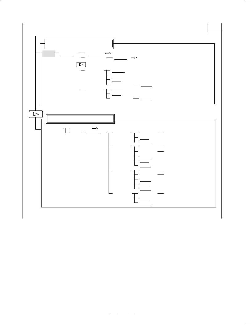
B±62705EN/03 |
1. DISPLAY AND OPERATION |
|
|
(1) |
|
|
|
|
2/2 |
|
|
|
|
|
|
Program directory display |
|
|
|
|
|
[LIB] |
[(OPRT)] |
[BG±EDT] |
See ªWhen the soft key [BG±EDT] is pressedº |
||
|
|
(O number) |
[O SRH] |
Return to the program |
|
|
[READ] |
[CHAIN] |
|
|
|
|
|
|
[STOP] |
|
|
|
|
|
[CAN] |
|
|
|
|
|
(O number) |
[EXEC] |
|
|
[PUNCH] |
[STOP] |
|
|
|
|
|
|
[CAN] |
|
|
|
|
|
(O number) |
[EXEC] |
|
Floppy directory display |
|
|
|
|
|
[FLOPPY] |
[PRGRM] |
Return to the program |
|
|
|
|
[DIR] |
[(OPRT)] |
[F SRH] |
(Numeral) |
[F SET] |
|
|
|
|
[CAN] |
|
|
|
|
|
[EXEC] |
|
|
|
|
[READ] |
(Numeral) |
[F SET] |
|
|
|
|
(Numeral) |
[O SET] |
|
|
|
|
[STOP] |
|
|
|
|
|
[CAN] |
|
|
|
|
|
[EXEC] |
|
|
|
|
[PUNCH] |
(Numeral) |
[F SET] |
|
|
|
|
(Numeral) |
[O SET] |
|
|
|
|
[STOP] |
|
|
|
|
|
[CAN] |
|
|
|
|
|
[EXEC] |
|
|
|
|
[DELETE] |
(Numeral) |
[F SET] |
|
|
|
|
[CAN] |
|
|
|
|
|
[EXEC] |
|
7

1. DISPLAY AND OPERATION B±62705EN/03
|
PROGRAM SCREEN |
|
Soft key transition triggered by the function key |
PROG |
|
|
|||
|
|
in the MDI mode |
|
|
|
|
|
|
|
|
|
|
|
|
PROG |
4. |
Program display |
|
|
|
[PRGRM] |
[(OPRT)] |
[BG±EDT] |
See ªWhen the soft key [BG±EDT] is pressedº |
Program input screen |
|
|
|
[MDI] |
[(OPRT)] |
[BG±EDT] |
See ªWhen the soft key [BG±EDT] is pressedº |
|
|
[START] |
[CAN] |
|
|
|
[EXEC] |
|
|
(Address) |
[SRH↓] |
|
|
(Address) |
[SRH↑] |
|
|
[REWIND] |
|
Current block display screen
[CURRNT] |
|
|
[(OPRT)] |
|
[BG±EDT] |
See •When the soft key [BG-EDT] is pressed" |
|||
|
|
||||||||
|
|
|
|
|
|
|
|
|
|
Next block display screen |
|
|
|
[NEXT] |
[(OPRT)] |
[BG±EDT] |
See ªWhen the soft key [BG±EDT] is pressedº |
Program restart display screen
[RSTR] |
|
|
[(OPRT)] |
|
|
[BG±EDT] |
See ªWhen the soft key [BG±EDT] is pressedº |
||
|
|
||||||||
|
|
|
|
|
|
|
|
|
|
8

B±62705EN/03 1. DISPLAY AND OPERATION
|
PROGRAM SCREEN |
|
Soft key transition triggered by the function key |
PROG |
|
|
|||
|
|
in the HNDL, JOG, or REF mode |
|
|
|
|
|
|
|
|
|
|
|
|
5.
PROG
Program display |
|
|
|
[PRGRM] |
[(OPRT)] |
[BG±EDT] |
See ªWhen the soft key [BG±EDT] is pressedº |
Current block display screen |
|
|
|
[CURRNT] |
[(OPRT)] |
[BG±EDT] |
See ªWhen the soft key [BG±EDT] is pressedº |
Next block display screen |
|
|
|
[NEXT] |
[(OPRT)] |
[BG±EDT] |
See ªWhen the soft key [BG±EDT] is pressedº |
Program restart display screen
[RSTR] |
[(OPRT)] |
[BG±EDT] |
See ªWhen the soft key [BG±EDT] is pressedº |
|
PROGRAM SCREEN |
|
Soft key transition triggered by the function key |
PROG |
|
|
|||
|
|
in the TJOG or THDL mode |
|
|
|
|
|
|
|
|
|
|
|
|
PROG |
6. |
|
|
|
Program input screen |
|
|
|
|
[MDI] |
[(OPRT)] |
[BG±EDT] |
See ªWhen the soft key [BG±EDT] is pressedº |
|
|
|
(O number) |
[O SRH] |
Return to the program |
|
|
(Address) |
[SRH↓] |
|
|
|
(Address) |
[SRH↑] |
|
|
|
[REWIND] |
|
|
Program directory display
[LIB] |
|
|
|
[(OPRT)] |
|
|
[BG±EDT] |
|
|
See ªWhen the soft key [BG±EDT] is pressedº |
|||||
|
|
|
|
|
|
|
|||||||||
|
|
|
|
|
|
|
|
|
|
|
|
|
|
|
|
|
|
|
|
|
|
|
|
(O number) |
|
|
[O SRH] |
Return to the program |
|||
|
|
|
|
|
|
|
|
|
|||||||
|
|
|
|
|
|
|
|
|
|
|
|
|
|
|
|
9
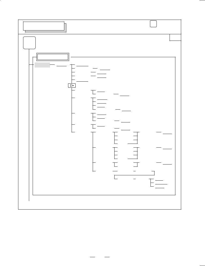
1. DISPLAY AND OPERATION |
B±62705EN/03 |
PROG
PROGRAM SCREEN Soft key transition triggered by the function key (When the soft key [BG±EDT] is pressed in all modes)
|
|
|
|
|
|
1/2 |
PROG |
7. |
|
|
|
|
|
|
|
|
|
|
|
|
Program display |
|
|
|
|
|
|
[PRGRM] |
[(OPRT)] |
[BG±END] |
|
|
|
|
|
|
(O number) |
[O SRH] |
|
|
|
|
|
(Address) |
[SRH↓] |
|
|
|
|
|
(Address) |
[SRH↑] |
|
|
|
|
|
[REWIND] |
|
|
|
|
|
|
[F SRH] |
[CAN] |
|
|
|
|
|
|
(N number) |
[EXEC] |
|
|
|
|
[READ] |
[CHAIN] (The cursor moves to the end of a program.) |
|||
|
|
|
[STOP] |
|
|
|
|
|
|
[CAN] |
|
|
|
|
|
|
(O number) |
[EXEC] |
|
|
|
|
[PUNCH] |
[STOP] |
|
|
|
|
|
|
[CAN] |
|
|
|
|
|
|
(O number) |
[EXEC] |
|
|
|
|
[DELETE] |
[CAN] |
|
|
|
|
|
|
(N number) |
[EXEC] |
|
|
|
|
[EX±EDT] |
[COPY] |
[CRSR~] |
(O number) |
[EXEC] |
|
|
|
|
[~CRSR] |
|
|
|
|
|
|
[~BTTM] |
|
|
|
|
|
|
[ALL] |
|
|
|
|
|
[MOVE] |
[CRSR~] |
(O number) |
[EXEC] |
|
|
|
|
[~CRSR] |
|
|
|
|
|
|
[~BTTM] |
|
|
|
|
|
|
[ALL] |
|
|
|
|
|
[MERGE] |
[~CRSR] |
(O number) |
[EXEC] |
|
|
|
|
[~BTTM] |
|
|
|
|
|
[CHANGE] |
(Address) |
[BEFORE] |
|
|
|
|
|
(Address) |
[AFTER] |
[SKIP] |
|
|
|
|
|
|
[1±EXEC] |
|
|
|
|
|
|
[EXEC] |
(1)(Continued on the next page)
10
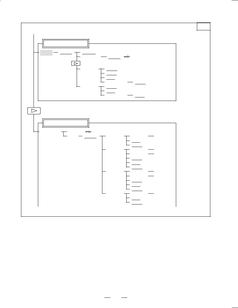
B±62705EN/03 |
1. DISPLAY AND OPERATION |
|
|
(1) |
|
|
|
|
2/2 |
|
|
|
|
|
|
Program directory display |
|
|
|
|
|
[LIB] |
[(OPRT)] |
[BG±EDT] |
|
|
|
|
|
(O number) |
[O SRH] |
Return to the program |
|
|
|
[READ] |
[CHAIN] |
|
|
|
|
|
[STOP] |
|
|
|
|
|
[CAN] |
|
|
|
|
|
(O number) |
[EXEC] |
|
|
|
[PUNCH] |
[STOP] |
|
|
|
|
|
[CAN] |
|
|
|
|
|
(O number) |
[EXEC] |
|
Floppy directory display |
|
|
|
|
|
[FLOPPY] |
[PRGRM] |
Return to the program |
|
|
|
|
[DIR] |
[(OPRT)] |
[F SRH] |
(Numeral) |
[F SET] |
|
|
|
|
[CAN] |
|
|
|
|
|
[EXEC] |
|
|
|
|
[READ] |
(Numeral) |
[F SET] |
|
|
|
|
(Numeral) |
[O SET] |
|
|
|
|
[STOP] |
|
|
|
|
|
[CAN] |
|
|
|
|
|
[EXEC] |
|
|
|
|
[PUNCH] |
(Numeral) |
[F SET] |
|
|
|
|
(Numeral) |
[O SET] |
|
|
|
|
[STOP] |
|
|
|
|
|
[CAN] |
|
|
|
|
|
[EXEC] |
|
|
|
|
[DELETE] |
(Numeral) |
[F SET] |
|
|
|
|
[CAN] |
|
|
|
|
|
[EXEC] |
|
11
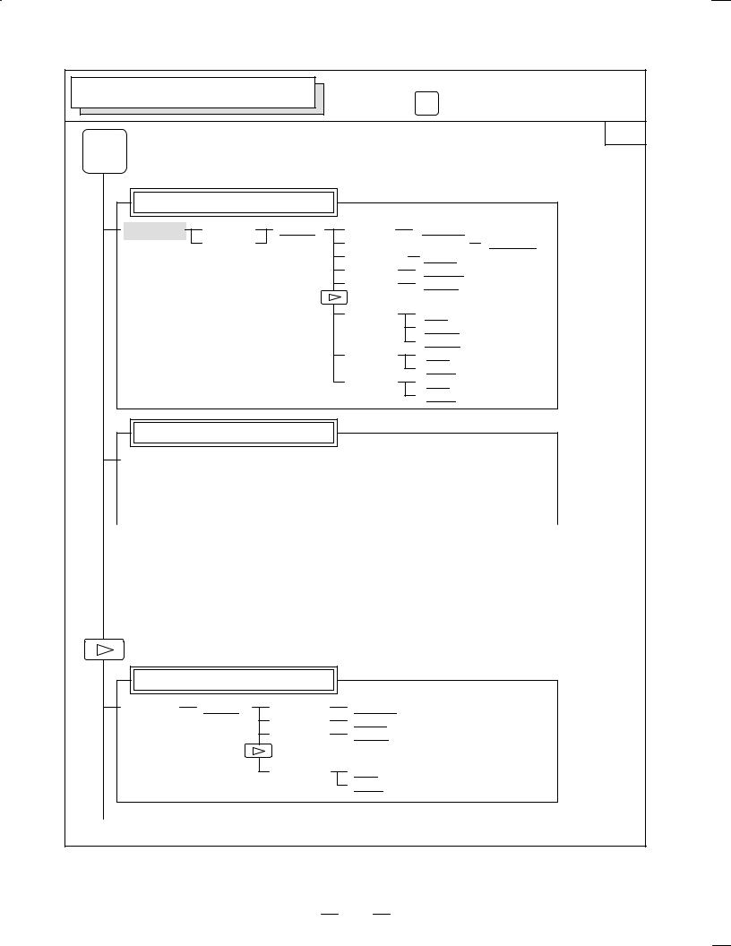
1. DISPLAY AND OPERATION |
B±62705EN/03 |
OFFSET/SETTING SCREEN (T series) |
Soft key transition triggered by the |
||||
function key |
OFFSET |
|
|||
|
|
|
|
||
|
|
|
|
SETTING |
|
OFFSET |
|
|
|
|
1/2 |
8. |
|
|
|
|
|
SETTING |
|
|
|
|
|
Tool offset screen |
|
|
|
|
|
[OFFSET] |
[WEAR] |
[(OPRT)] |
(Number) |
[NO SRH] |
|
|
[GEOM] |
|
(Axis name and numeral) |
[MEASUR] |
|
|
|
|
(Axis name) |
[INP.C.] |
|
|
|
|
(Numeral) |
[+INPUT] |
|
|
|
|
(Numeral) |
[INPUT] |
|
|
|
|
[CLEAR] |
[ALL] |
|
|
|
|
|
[WEAR] |
|
|
|
|
|
[GEOM] |
|
|
|
|
[READ] |
[CAN] |
|
|
|
|
|
[EXEC] |
|
|
|
|
[PUNCH] |
[CAN] |
|
|
|
|
|
[EXEC] |
|
Setting screen
|
|
|
|
[SETING] |
|
|
|
[(OPRT)] |
|
|
(Number) |
|
|
|
|
[NO SRH] |
|
|
|||||||||||||||||
|
|
|
|
|
|
|
|
|
|
|
|
||||||||||||||||||||||||
|
|
|
|
|
|
|
|
|
|
|
|
|
|
|
|
|
|
[ON:1] |
|
|
|
|
|
|
|
|
|
|
|
|
|
||||
|
|
|
|
|
|
|
|
|
|
|
|
|
|
|
|
|
|
|
|
|
|
|
|
|
|
|
|
|
|||||||
|
|
|
|
|
|
|
|
|
|
|
|
|
|
|
|
|
|
|
|
|
|
|
|
|
|
|
|
|
|
|
|||||
|
|
|
|
|
|
|
|
|
|
|
|
|
|
|
|
|
|
|
|
|
|
|
|
|
|
|
|
|
|
|
|
|
|
|
|
|
|
|
|
|
|
|
|
|
|
|
|
|
|
|
|
|
|
[OFF:0] |
|
|
|
|
|
|
|
|
|
|
|
|
|
||||
|
|
|
|
|
|
|
|
|
|
|
|
|
|
|
|
|
|
|
|
|
|
|
|
|
|
|
|
|
|
|
|||||
|
|
|
|
|
|
|
|
|
|
|
|
|
|
|
|
|
|
|
|
|
|
|
|
|
|
|
|
|
|
|
|
|
|
||
|
|
|
|
|
|
|
|
|
|
|
|
|
|
|
|
|
|
(Numeral) |
|
|
|
|
[+INPUT] |
|
|
||||||||||
|
|
|
|
|
|
|
|
|
|
|
|
|
|
|
|
|
|
|
|
|
|
|
|||||||||||||
|
|
|
|
|
|
|
|
|
|
|
|
|
|
|
|
|
|
(Numeral) |
|
|
|
|
[INPUT] |
|
|
||||||||||
|
|
|
|
|
|
|
|
|
|
|
|
|
|
|
|
|
|
|
|
|
|
||||||||||||||
|
|
|
|
|
|
|
|
|
|
|
|
|
|
|
|
|
|
|
|
|
|
|
|
|
|
|
|
|
|
|
|
|
|
|
|
|
|
|
|
|
|
|
|
|
|
|
|
|
|
|
|
|
|
|
|
|
|
|
|
||||||||||||
|
|
|
|
|
Workpiece coordinate system setting screen |
|
|
|
|
|
|
|
|
|
|
|
|
|
|||||||||||||||||
|
|
|
|
|
|
|
|
|
|
|
|
|
|
|
|
|
|
|
|
|
|
|
|||||||||||||
|
|
|
|
|
|
|
|
|
|
|
|
|
|
|
|
|
|
|
|
|
|
||||||||||||||
|
|
|
|
[WORK] |
|
|
[(OPRT)] |
|
|
|
(Number) |
|
|
|
[NO SRH] |
|
|
||||||||||||||||||
|
|
|
|
|
|
|
|
|
|
|
|||||||||||||||||||||||||
|
|
|
|
|
|
|
|
|
|
|
|
|
|
|
|
|
|
|
|
|
|
|
|
|
|
||||||||||
|
|
|
|
|
|
|
|
|
|
|
|
|
|
|
|
(Axis name and numeral) |
|
|
[MEASUR] |
||||||||||||||||
|
|
|
|
|
|
|
|
|
|
|
|
|
|
|
|
|
|||||||||||||||||||
|
|
|
|
|
|
|
|
|
|
|
|
|
|
|
|
(Numeral) |
|
|
|
|
[+INPUT] |
|
|
||||||||||||
|
|
|
|
|
|
|
|
|
|
|
|
|
|
|
|
|
|
|
|
||||||||||||||||
|
|
|
|
|
|
|
|
|
|
|
|
|
|
|
|
(Numeral) |
|
|
|
|
[INPUT] |
|
|
|
|||||||||||
|
|
|
|
|
|
|
|
|
|
|
|
|
|
|
|
|
|
|
|
||||||||||||||||
|
|
|
|
|
|
|
|
|
|
|
|
|
|
|
|
|
|
|
|
|
|
|
|
|
|
|
|
|
|
|
|
|
|
|
|
Macro variables display screen |
|
|
|
[MACRO] |
[(OPRT)] |
(Number) |
[NO SRH] |
|
|
(Axis name) |
[INP.C.] |
|
|
(Numeral) |
[INPUT] |
|
|
[PUNCH] |
[CAN] |
|
|
|
[EXEC] |
(1)(Continued on the next page)
12
Loading...