


GFK-1046E
Table of contents
 Loading...
GE Fanuc Automation
Computer Numerical Control Products
Servo and Spindle Motors
Exposed to Liquids
GFK-1046E April 1999

GFL-001
Warnings, Cautions, and Notes
as Used in this Publication
Warning
Warning notices are used in this publication to emphasize that hazardous voltages, currents,
temperatures, or other conditions that could cause personal injury exist in this equipment or
may be associated with its use.
In situations where inattention could cause either personal injury or damage to equipment, a
Warning notice is used.
Caution
Caution notices are used where equipment might be damaged if care is not taken.
Note
Notes merely call attention to information that is especially significant to understanding and
operating the equipment.
This document is based on information available at the time of its publication. While efforts
have been made to be accurate, the information contained herein does not purport to cover all
details or variations in hardware or software, nor to provide for every possible contingency in
connection with installation, operation, or maintenance. Features may be described herein
which are not present in all hardware and software systems. GE Fanuc Automation assumes
no obligation of notice to holders of this document with respect to changes subsequently made.
GE Fanuc Automation makes no representation or warranty, expressed, implied, or statutory
with respect to, and assumes no responsibility for the accuracy, completeness, sufficiency, or
usefulness of the information contained herein. No warranties of merchantability or fitness for
purpose shall apply.
©Copyright 1999 GE Fanuc Automation North America, Inc.
All Rights Reserved.
Preface
GFK-1046E iii
Content of this Manual
Chapter 1. Protection Standards: Provides basic product information and how they relate
to IEC standards.
Chapter 2. User Specifications: Provides a tool that end users can use to help their
machine suppliers provide machines that meet consistent standards of protection.
Chapter 3. Application Guide: Provides a foundation for the machine tool builder by
pointing out the elements that can affect coolant entry, modes of motor failure,
and more extreme methods of keeping motors dry.
Chapter 4. Machine Runoff Checklist: This checklist can be used during machine design
and test or after installation at the user site.
Chapter 5. Preventive Maintenance: Describes the steps that can be used to identify
potential motor failures as well as basic preventive maintenance procedures.
The following table identifies the chapters which will be most useful to each type of user.
Refer to this Chapter:
Function 1 2 3 4 5
Machine Tool Builder Yes Yes Yes Yes No
End User / Specifier No Yes Yes Yes No
User Maintenance / Service No No Yes Yes Yes
Related Publications
Publication S Series αα ß Series
Servo Descriptions Manual GFZ-65002E GFZ-65142E
Servo Maintenance Manual GFZ-65005E GFZ-65165E
Spindle Descriptions Manual GFZ-65042E GFZ-65152E
Spindle Maintenance Manual GFZ-65045E GFZ-65165E
ß Series Servo Motor Descriptions Manual GFZ-65232EN

Contents
GFK-1046E v
Chapter 1 Protection Standards............................................................................................ 1-1
Oil Seals............................................................................................................................1-1
Connectors.........................................................................................................................1-2
IEC Protection Standards...................................................................................................1-3
Chapter 2 User Specifications................................................................................................ 2-1
All Motor Applications ......................................................................................................2-1
Motors Subjected to Liquids...............................................................................................2-5
Chapter 3 Application Guide ................................................................................................. 3-1
Boot System.......................................................................................................................3-2
IEC Standards....................................................................................................................3-3
When Coolant Enters a Motor............................................................................................3-4
Drains and Pressurization...................................................................................................3-4
Fans and Derating..............................................................................................................3-4
Chapter 4 Machine Runoff Checklist.................................................................................... 4-1
Checklist............................................................................................................................4-2
Chapter 5 Preventive Maintenance....................................................................................... 5-1
Maintenance for Drives in a Normal Environment...............................................................5-2
Maintenance for Drives in a Wet Environment.................................................................... 5-3
Modification to the Motor ..................................................................................................5-4
GFK-1046E 1 - 1
Chapter
Protection Standards
Developing and maintaining a highly efficient and productive system involves the machine tool
builder, the drives/controls supplier, and the end user. The system design, selected components,
and manner in which the equipment is installed, used, and maintained all contribute to the uptime
of the system.
Oil Seals
Oil seals are designed to keep oil from entering the motor through the shaft end. Oil seals do not,
however, prevent the entry of any liquids under pressure.
Caution
When liquid is present during the cooling period of a motor, lower air
pressure in the motor may result in the motor breathing in the liquids.
1
1 - 2 Servo and Spindle Motors Exposed to Liquids - April 1999 GFK-1046E
1
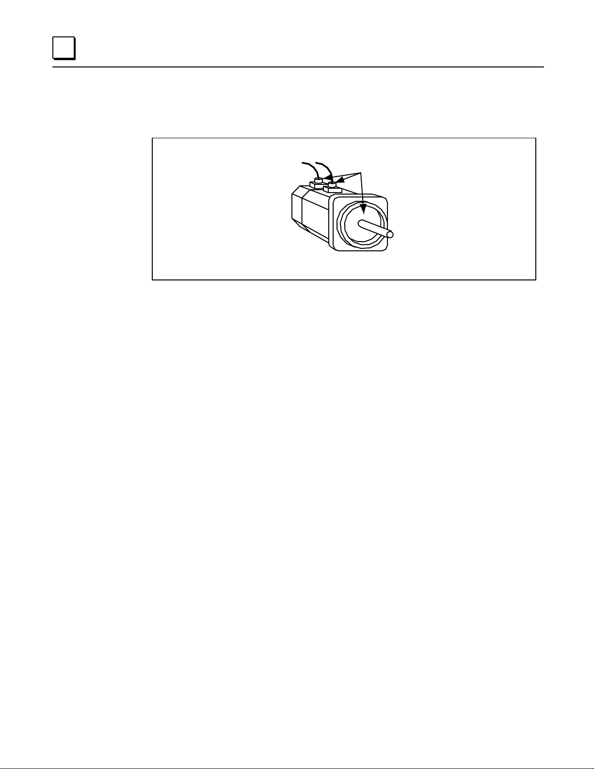
The following illustration identifies the most vulnerable areas for coolant entry.
Figure 1 - 1. Coolant Entry
Note
Foot-mount style spindle motors are only supplied with shaft oil seals as an
available option.
Connectors
Servo motor models 0S through 40S and α3 through α40 have the same type of cable connector
system (power, feedback, and brake). The cable connector system is designed to accept MS-type
connectors.
SP-style, α1, and α2 motors use a D-type connector system. The D-type connector system has
connectors that are as effective as MS-protected types.
Most Vulnerable
for Coolant Entry
a48031
GFK-1046E Chapter 1 Protection Standards 1 - 3
1
IEC Protection Standards
GE Fanuc motors are designed to meet the IEC protection standards listed in Table 1-1. These
standards are based on two characteristics, the first being protection from solid objects and the
second being protection from water.
Table 1 - 1. IEC Protection Standards
Standard * Description
Protection from Solid Objects
IP4x Protected against solid objects greater than 1 mm thickness or diameter.
IP5x Protected against dust. "Ingress of dust is not totally prevented, but dust does not enter in sufficient
quantity to interfere with satisfactory operation of the equipment."
IP6x Dust tight. "No ingress of dust."
Protection from Water
IPx2 Protected against dripping water, rate equivalent to 3-5 mm of rain per minute.
IPx4 Protected against splashing water from any direction.
IPx5 Protected from harmful damage due to water jets, according to the following test:
• Spray from all angles of 12.5 liters/minute.
• Nozzle diameter = 6.3 mm.
• Pressure = 30 kN/m
2
(0.3 bar).
• Distance = 3 m.
• Duration = 3 minutes.
IPx7
(see note below)
Protected against the effects of immersion, according to the following test:
• Surface of the water level shall be at least 150 mm above the highest point of the machine.
• Lowest point of the machine must be at least 1 meter below the surface of the water.
• Duration of the test must be at least 30 minutes.
• Water temperature must not differ from that of the machine by more than 5° C.
* Each standard listed below also satisfies the requirements of the lower rated standards beneath it.
For example, IPx5 also meets the standards for IPx4, IPx3, IPx2, and IPx1. For more information, refer to CEI/IEC 34-5; 1991.
Note
By agreement between the manufacturer and the user, this test may be replaced
by the following procedure:
The machine should be tested with an inside air pressure of about 10 kPa (0.1
bar). The duration of the test is one minute. If no air leaks out during the test,
the test is satisfactory. Air leakage may be detected either by submersion, with
water just covering the machine, or by the application on to it of a solution of
soap in water.
GE Fanuc tests according to this alternate procedure. Using the other procedure
requires removing the end cap and checking for water in the motor. This
destroys the integrity of the seal.
1 - 4 Servo and Spindle Motors Exposed to Liquids - April 1999 GFK-1046E
1
IEC ratings provide a good indication of the expected performance of GE Fanuc motors because
they are test-based systems. However:
• To meet the standard, the shaft end and electrical connections (connector or terminal box)
must be appropriately protected by the customer.
• Because the second characteristic is based on water, the effect of various coolant materials
cannot be accurately predicted.
• Motors built to meet IP65 or IP67 go through a different manufacturing process. These
protection levels cannot be readily added in the field.
• If a motor is modified (i.e., by rotating the connector, by removing the end cap to change the
encoder, etc.), the protection rating is voided.
• Oil seals and connectors are the same in both standard motors and in those motors with
higher levels of protection.
• Compared to standard motors, IP67-rated motors have additional materials applied to mating
surfaces. Depending on the surfaces, these may include varnish, rubber-based gaskets, and
RTVs. In addition, a polyurethane-based paint is applied to the exterior painted surfaces, and
motor is tested by submersion for leak test.
Note
To maximize the service provided by the motors, regardless of their protection
level, they should be protected from continuous wetting by coolants.
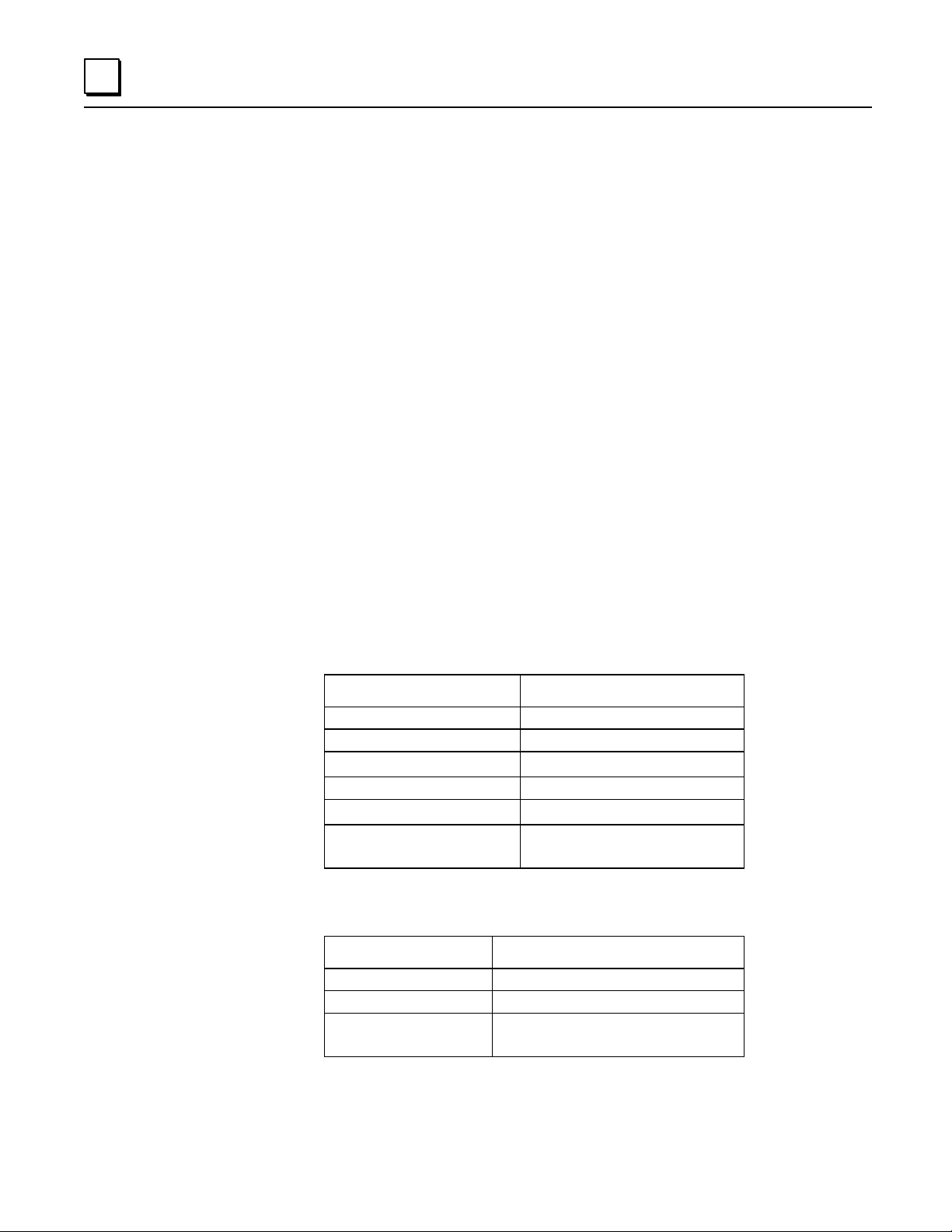
Table 1 - 2. Servo Motors
Model IEC Standard
Hollow Shaft "T" Motors Not rated
5-0 Not rated
4-0S, 3-0S, 50S, 60S, 70S, α0.5
Not rated
2-0SP through 30S IP55 Standard
α1 through α150, β0.5 through β6
IP65 Standard (IP67 Optional)
40S and α40
IP55 Standard (excluding fan)
IP67 Optional (excluding fan)
Table 1 - 3. Spindle Motors
Model IEC Standard
Built-in Motors Not rated
Selected 1S through 3S IP65 Optional
All Others IP54 (excluding fan and terminal box)
IP44 (fan and terminal box included)
Loading...