


Back to Home
OPERATION MANUAL
FH550SX / FH630SX
HORIZONTALMACHINING CENTER
( FANUC - 30i,31i )
TOYODA MACHINE WORKS, LTD.

You are requested to read this manual thoroughly, and comprehend its contents fully prior to starting the operation of the machine.
You are also requested to keep this manual in your designated place in order to get a help of the manual.
Transfer of this machine
Follow the steps below without fail when you transfer this machine to someone else.
-Give this manual and attached manuals to the transferee.
-Refer to the warning labels, and confirm them all.
-If you find there is no label, nor manuals, request for them to us.
If you transfer the machine to someone, never fail to inform us of the transferring.
You are requested to obey the followings;
-This machine may be in the category of restricted items under the ?Foreign Exchange and Foreign Trade Control Law of Japan?.
To export this machine you must get the export license according to the law.
-This machine was manufactured originally according to laws, regulations and standards of the country, or the area.
This means that you are not allowed to export it to any other country or area where law, regulations and standards are different from those of the original country or area.
Warranty
Free-of-charge repair
-A failure or damage resulting from using properly the machine according to the operational standards (described in the manual), manuals and indicating labels may be repaired free of charge only if it is within the warranty period.
-The warranty may cover only the main body of the machine delivered. The warranty does not cover the direct or indirect loss caused by a failure.
-The warranty period is one year, starting from the acceptance date of the machine after its delivery.
Pay repair
-Repair after the warranty period is charged.
Despite the effective warranty period the repair described below is charged.
1.Any failure or damage resulted from the misapplication by a customer, or modifying or repairing by a customer without our consents.
2.Unexpected failure or damage arising from a fire, act of God, lightning or abnormal voltage.
3.Failure or damage due to an improper handling such as a fall at the time of transporting or moving at a customer?s.
4.Failure or damage caused by a customer who does not follow the handling procedures.
5.Consumption, abrasion or deterioration of expendables.
6.The malfunction and damage which were produced using the other oil when there was designation oil. Moreover, the malfunction and damage which were produced since the oil with which a consistency and the purpose of use are different was used even when there was no designation oil
Introduction to this manual
-This manual is subject to change without notice when this type of machine and its manual need improving. You are requested to be generous to a small discrepancy, if any, between the machine and its manual.
If you find a difference between the machine and its manual, or if you have a question, please let us know.
Disposal
Dispose of the machine itself and its peripherals in accordance with the laws established by the country and relevant administrative bodies.
1. Disposal of the Machine and Peripherals
The disposal work must be entrusted to a specialist contractor.
Specialist knowledge is required to disassemble the linear motor that drives wheel feed.
Ask a person who has been trained in the disassembly and assembly of linear motors to do this work. When disposing of the accumulator, release the nitrogen gas from it, then disassemble it in such a way that it cannot be reassembled.
Sort parts for disposal on the basis of your own in-house regulations, and have a specialist contractor do the disposal work from time to time.
If you have any questions about the materials that parts are made of, or other matters, please contact us.
This system may include devices which use CFC as the refrigerant.
When CFC is used in a device, it is stated on the name plate of the device.
It is prohibited to release kinds of CFC gas in the atmosphere by the CFC Recovery and Decomposition Law.
When disposing a device that uses CFC, you need to ensure that the gas is recovered safely by a contractor who is authorized to recover kinds of CFC, Category 1, by the municipal authority.
2. Disposal of Consumable Parts
Sort the parts according to your in-house rules, and entrust the disposal work to a specialist contractor from time to time.
(1)Coolant
(2)Chips
(3)Spent lubricating oil and hydraulic oil
(4)Battery for memory back-up
When disposing of the battery for memory back-up (lithium battery), abide by the following points and handle the batteries in accordance with any local governmental regulations.
(1)Do not mix batteries up with each other and avoid the possibility of shorting by putting the each battery into a separate plastic bag.
(2)Ensure that the container in which the batteries are collected is made of an insulating material.
(3)Make sure the batteries are not made wet by rain or other water.
(4)Do not mix the batteries with items identified as hazardous under the fire laws, or place these items near the batteries.
(5)Do not place the batteries near fire or in any location where they will be subject to high temperatures.
(6)Do not disassemble the batteries, heat them, or throw them into fire.
FOREWORD
This operating manual was created in order to let you know about an everyday handling and safety matter of horizontal machining center FH550SX/FH630SX of our company.
This operation manual consists of the ?Safety Manual? and ?Operation Manual? mainly for the operators who will use our horizontal machining center FH550SX/FH630SX for the first time: the contents regarding operational safety are described in the former manual, while the contents regarding machine operation are described in the latter manual.
Please note in advance that some of the optional functions described in this operation manual may not be included in your machine.
If necessary, refer the following documents as well:
FH550SX/630SX : Maintenance Manual
BEFORE READING THIS MANUAL
FH550SX/630SX
1. How to See Manual
This manual is consisted in the following constructions.
3. Manually Operation 
 CHAPTER
FH550SX/630SX
3.1 Zero Return |
|
|
Model |
|||||
|
|
|
|
|
|
|
|
|
|
|
|
|
|
|
|
|
|
Section
3.1.1 Automatic Zero Return of all axis
Paragraph
Symbols
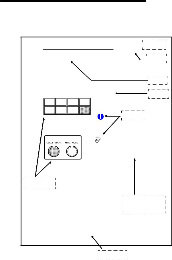
During the origin return cycle, the START pushbutton lamp is light.
Button, lamp etc.
Contents of operation, explanation etc.
3-4
Page Number
Before Reading Manual 1
BEFORE READING THIS MANUAL
|
|
FH550SX/630SX |
|
|
|
|
|
|
Explanation of items on the previous page |
||
Chapter ---------------------- |
Main Topics and title of the chapter |
|
Section ---------------------- |
Sub-topics and items out of chapter |
|
Paragraph ------------------- |
Task description and items out of chapter and section |
|
Model ------------------------ |
The model name of this manual |
|
Representation of Safety Caution Marks
This manual contains the following indications to enable you to use the machine safely, and in order to prevent hazards to personnel and damage to property.
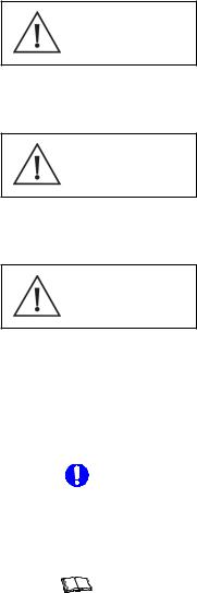
DANGER |
Failure to observe items in this category will result in death or severe |
injury. |
Failure to observe items in this category can lead to death or severe
WARNING injury.
Failure to observe items in this category can lead to injuries or property
CAUTION damage.
In addition to the above, the following indications are also used in this manual.
<IMPORTANT> |
This is an item that requires attention during machine operation or other |
|
work. |
|
Failure to observe such items can lead to damage to the machine. |
<NOTE> |
This is information for reference during machine operation and program- |
|
ming. |
Before Reading Manual 2

BEFORE READING THIS MANUAL
FH550SX/630SX
Operation procedure & explanation ..... Operational procedure and explanation is described.
* (1) (2) •E•E•E •E•E• E ar e used t o s how the numbe r e-
quential process. Follow this sequence, then you can perform it in right order.
* (a) (b) •E•E• E ar e use d when there i s several select i on the operational procedures, and are written as per title of list.
*[START] etc shows button.
*{Cutting Feed} etc shows selectable switch.
*<Power Source> etc shows lamp.
*?TOUCH SENSOR? etc shows display on screen.
Buttons & lamps etc.
....... Buttons, Lamps, etc are shown in picture or drawing. Button to be activated are shadowed, and easy to be recognized. Picture or drawing was prepared with the most current information at the time of publication. However, there may be instances of configuration changes from an actual machine, so read it carefully.
Page number ....... |
3-4 means the 4th page in the chapter 3. |
Before Reading Manual 3
CONTENTS |
|
|
PAGE |
Foreword |
|
Before Reading this Manual |
|
1. Safety Precaution ----------------------------------------------------------------------------------------------------- |
1-1 |
1.1 Items to Keep Worker?s Safety ------------------------------------------------------------------------------- |
1-1 |
1.2 Items to be Kept during the Machinery Operation and to Protect the Machine -------------------- |
1-1 |
1.3 Safety Precaution for Each Work ----------------------------------------------------------------------------- |
1-2 |
1.3.1 During Operation -------------------------------------------------------------------------------------------- |
1-2 |
1.3.2 For Setup Change ------------------------------------------------------------------------------------------ |
1-2 |
1.3.3 For Daily Inspection ---------------------------------------------------------------------------------------- |
1-3 |
1.3.4 Upon an Error ------------------------------------------------------------------------------------------------ |
1-3 |
1.4 Label ----------------------------------------------------------------------------------------------------- |
1-4 |
1.4.1 Warning Label Attaching Position ----------------------------------------------------------------------- |
1-4 |
1.4.2 Cautions on Warning Labels ----------------------------------------------------------------------------- |
1-5 |
1.5 Relation Law, Standard, Datum ------------------------------------------------------------------------------- |
1-8 |
2. Machine Outline ----------------------------------------------------------------------------------------------------- |
2-1 |
2.1 General Configuration ------------------------------------------------------------------------------------------- |
2-1 |
2.2 Controlled Axis ---------------------------------------------------------------------------------------------------- |
2-2 |
2.3 Operation Panel -------------------------------------------------------------------------------------------------- |
2-3 |
2.3.1 Machine Controls Description ---------------------------------------------------------------------------- |
2-3 |
2.3.2 Main Operation Panel -------------------------------------------------------------------------------------- |
2-4 |
2.3.3 Handle Feed Operation Panel ---------------------------------------------------------------------------- |
2-16 |
2.3.4 Magazine Operation Panel ------------------------------------------------------------------------------- |
2-17 |
2.3.5 Pallet Changer Operation Panel ------------------------------------------------------------------------- |
2-20 |
2.3.6 Chip Conveyor Operation Panel ------------------------------------------------------------------------- |
2-22 |
2.3.7 Lamps ----------------------------------------------------------------------------------------------------- |
2-24 |
2.4 Door Interlock ----------------------------------------------------------------------------------------------------- |
2-25 |
2.4.1 Operator?s Door Interlock --------------------------------------------------------------------------------- |
2-25 |
2.4.2 Magazine Door Interlock ---------------------------------------------------------------------------------- |
2-25 |
2.4.3 Pallet Changer Door Interlock ---------------------------------------------------------------------------- |
2-26 |
2.4.4 Explanation of Operation Mode -------------------------------------------------------------------------- |
2-27 |
3. Operation Method ----------------------------------------------------------------------------------------------------- |
3-1 |
3.1 From Power ON to Pump ON --------------------------------------------------------------------------------- |
3-1 |
3.1.1 Before Turning Power ON --------------------------------------------------------------------------------- |
3-1 |
3.1.2 For Bringing the Machine into Operable Condition -------------------------------------------------- |
3-2 |
3.1.3 Pump ON ----------------------------------------------------------------------------------------------------- |
3-4 |
3.2 Stopping the Machine ------------------------------------------------------------------------------------------- |
3-7 |
3.2.1 For Stopping the Machine in an Emergency ---------------------------------------------------------- |
3-7 |
3.2.2 Stopping the Operation at the End of Work ----------------------------------------------------------- |
3-9 |
3.2.3 For Stopping the Machine during Memory-, Tape-, and MDI-mode Operation ----------------- |
3-10 |
3.3 Turning Off the Power ------------------------------------------------------------------------------------------- |
3-13 |
|
3.3.1 For Turning Off the NC Power ---------------------------------------------------------------------------- |
3-13 |
|
3.3.2 For Turning OFF the Main Power ----------------------------------------------------------------------- |
3-13 |
|
3.4 Origin Return Operation ----------------------------------------------------------------------------------------- |
3-14 |
|
3.4.1 |
For Returning All Axes to their Origins ----------------------------------------------------------------- |
3-14 |
3.4.2 |
Each Axis Origin Return ----------------------------------------------------------------------------------- |
3-15 |
3.4.3 For Performing Zero Return in MDI Mode -------------------------------------------------------------- |
3-16 |
|
3.5 Feed Operate ----------------------------------------------------------------------------------------------------- |
3-19 |
|
3.5.1 Handle Feed ------------------------------------------------------------------------------------------------- |
3-19 |
|
3.5.2 Jog Feed ----------------------------------------------------------------------------------------------------- |
3-20 |
|
3.5.3 Rapid Feed --------------------------------------------------------------------------------------------------- |
3-21 |
|
3.5.4 Turning Operation of Table -------------------------------------------------------------------------------- |
3-22 |
|
3.6 Spindle Rotating Operation ------------------------------------------------------------------------------------- |
3-25 |
|
3.6.1 Setting of Spindle Speed ---------------------------------------------------------------------------------- |
3-25 |
|
3.6.2 Spindle Rotating Operation ------------------------------------------------------------------------------- |
3-28 |
|
3.6.3 Stopping the Spindle --------------------------------------------------------------------------------------- |
3-38 |
|
3.6.4 |
For Stopping the Spindle Orientation ------------------------------------------------------------------- |
3-42 |
3.7 Magazine Operation --------------------------------------------------------------------------------------------- |
3-45 |
|
3.7.1 For Rotating by Jogging ----------------------------------------------------------------------------------- |
3-45 |
|
3.7.2 For Rotating in Continuous Mode ----------------------------------------------------------------------- |
3-47 |
|
3.8 Mounting or Dismounting a Tool ------------------------------------------------------------------------------ |
3-49 |
|
3.8.1 For Mounting a Tool ---------------------------------------------------------------------------------------- |
3-49 |
|
3.8.2 For Pullout a Tool from the Magazine ------------------------------------------------------------------ |
3-52 |
|
3.9 Tool Change Operation ------------------------------------------------------------------------------------------ |
3-54 |
|
3.9.1 For Put the Tool from Magazine to Spindle ------------------------------------------------------------ |
3-54 |
|
3.9.2 For Replacing the Magazine Tool with the Spindle Tool -------------------------------------------- |
3-57 |
|
3.9.3 For Stopping the Spindle Tool in the Magazine ------------------------------------------------------- |
3-60 |
|
3.10 Pallet Operation ------------------------------------------------------------------------------------------------- |
3-63 |
|
3.10.1 For Turning the Pallet Manually ------------------------------------------------------------------------ |
3-63 |
|
3.10.2 Pallet Change ---------------------------------------------------------------------------------------------- |
3-64 |
|
3.10.3 Pallet Confirmation ---------------------------------------------------------------------------------------- |
3-67 |
|
3.11 Discharge or Stop of Coolant, Tapping Oil, etc. ---------------------------------------------------------- |
3-70 |
|
3.11.1 Coolant ----------------------------------------------------------------------------------------------------- |
3-70 |
|
3.11.2 For Discharging Air Blow and Cleaning Air Blow --------------------------------------------------- |
3-82 |
|
3.12 Internal Chip Conveyor Operation --------------------------------------------------------------------------- |
3-86 |
|
3.12.1 For Turning the Internal Chip Conveyor --------------------------------------------------------------- |
3-86 |
|
3.12.2 For Stopping the Internal Chip Conveyor ------------------------------------------------------------- |
3-86 |
|
3.13 Take up Chip Conveyor Operation --------------------------------------------------------------------------- |
3-87 |
|
3.13.1 For Turning the Take up Chip Conveyor in Automatic Mode ------------------------------------- |
3-87 |
|
3.13.2 For Turning the Take up Chip Conveyor Normal Direction in Manual Mode ------------------ |
3-88 |
|
3.13.3 For Turning the Take up Chip Conveyor Counterclockwise Direction in Manual Mode ----- |
3-89 |
|
4. Auto Operation ----------------------------------------------------------------------------------------------------- |
4-1 |
|
4.1 Operation by MDI Program ------------------------------------------------------------------------------------- |
4-1 |
|
4.2 Operation from Calling Memory Program ------------------------------------------------------------------- |
4-3 |
|
|
4.3 |
Continuous Operation ------------------------------------------------------------------------------------------- |
4-5 |
|
4.3.1 Before Processing 2 Pallets Same Workpiece ------------------------------------------------------ |
4-5 |
|
|
4.3.2 Before Processing 2 Pallets Different Workpiece --------------------------------------------------- |
4-5 |
|
|
4.3.3 Before 1 Pallet Cycle -------------------------------------------------------------------------------------- |
4-6 |
|
|
4.3.4 How to Continuous Operation ---------------------------------------------------------------------------- |
4-6 |
|
|
4.4 |
Setting of Various Data ----------------------------------------------------------------------------------------- |
4-8 |
|
4.4.1 To Input Tool Offset ----------------------------------------------------------------------------------------- |
4-8 |
|
|
4.4.2 To Input Work Coordinate --------------------------------------------------------------------------------- |
4-11 |
|
|
4.4.3 To Input Common Variables ------------------------------------------------------------------------------ |
4-14 |
|
5. Editing Program ----------------------------------------------------------------------------------------------------- |
5-1 |
||
|
5.1 |
Display of Program List ----------------------------------------------------------------------------------------- |
5-1 |
|
5.2 |
Program Search -------------------------------------------------------------------------------------------------- |
5-2 |
|
5.3 |
Program New Make ---------------------------------------------------------------------------------------------- |
5-4 |
|
5.4 |
Program Appends a Part, Change, Delete ------------------------------------------------------------------ |
5-6 |
|
5.5 |
Program Delete --------------------------------------------------------------------------------------------------- |
5-8 |
|
5.6 |
Each Data Input/Output by Memory Card ----------------------------------------------------------------- |
5-10 |
|
5.6.1 Output of Machining Program ---------------------------------------------------------------------------- |
5-10 |
|
|
5.6.2 Input of Machining Program ------------------------------------------------------------------------------ |
5-13 |
|
|
5.6.3 Input/Output of Offset -------------------------------------------------------------------------------------- |
5-15 |
|
|
5.6.4 Input/Output of Macro -------------------------------------------------------------------------------------- |
5-16 |
|
|
5.6.5 Output of Parameter ---------------------------------------------------------------------------------------- |
5-17 |
|
|
5.7 |
Display of WINDOW --------------------------------------------------------------------------------------------- |
5-18 |
|
5.7.1 Display Lamp Illumination --------------------------------------------------------------------------------- |
5-18 |
|
|
5.7.2 Display Function Switch ---------------------------------------------------------------------------------- |
5-19 |
|
|
5.7.3 Display NC Switch ------------------------------------------------------------------------------------------ |
5-20 |
|
|
5.7.4 Display OP Supporter-------------------------------------------------------------------------------------- |
5-21 |
|
6. |
Daily Check ----------------------------------------------------------------------------------------------------- |
6-1 |
|
|
6.1 |
Check before Turning Power ON ------------------------------------------------------------------------------ |
6-1 |
7. |
NC Function List ----------------------------------------------------------------------------------------------------- |
7-1 |
|
|
7.1 |
Preparatory Function (G code) -------------------------------------------------------------------------------- |
7-1 |
|
7.2 |
Auxiliary Function (M code) ------------------------------------------------------------------------------------ |
7-6 |
|
7.2.1 Auxiliary Function List ------------------------------------------------------------------------------------- |
7-7 |
|
|
7.2.2 Explanation of Auxiliary Function ----------------------------------------------------------------------- |
7-9 |
|
|
7.3 |
Spindle Speed Function (S code) ----------------------------------------------------------------------------- |
7-15 |
|
7.4 |
Cutting Feed Rate Function (F code) ------------------------------------------------------------------------ |
7-15 |
|
7.5 |
Tool Offset Amount (H/D code) -------------------------------------------------------------------------------- |
7-15 |
|
7.6 |
Tool Function (T code) ------------------------------------------------------------------------------------------ |
7-15 |
8. Special Function ----------------------------------------------------------------------------------------------------- |
8-1 |
8.1 Heat Displacement Compensation Function for Spindle ------------------------------------------------- |
8-1 |
8.2 Tool Breakage Detection ---------------------------------------------------------------------------------------- |
8-3 |
8.2.1 Magazine Tool Inspection --------------------------------------------------------------------------------- |
8-3 |
8.2.2 Cycle Diagram ----------------------------------------------------------------------------------------------- |
8-4 |
8.2.3 Tool Inspection Unit Jog Mode --------------------------------------------------------------------------- |
8-4 |
8.2.4 Machining Program ----------------------------------------------------------------------------------------- |
8-5 |
8.2.5 M06 Macro Program --------------------------------------------------------------------------------------- |
8-6 |
8.2.6 Tool Inspection Traveling Amount Calculation Program --------------------------------------------- |
8-8 |
8.2.7 Tool Inspection Unit Parameter -------------------------------------------------------------------------- |
8-9 |
1. SAFE PRECAUTION
FH550SX/630SX
1.1Items to Keep Worker![]() s Safety
s Safety
(1)The factory controller (equipment controller) must prohibit everyone other than those who have undergone sufficient safety education, from entering the factory and the machine installation site for safety reasons. If those who have not undergone sufficient safety education carelessly enter the factory and the machine installation site, a fatal accident may result.
(2)Prior to machine operation, always confirm the safety of the other personnel in the immediate vicinity of the machine. Negligence of this precaution may lead to accidents such as getting caught in rotating parts or getting jammed between movable parts, resulting in injuries.
(3)Do not leave objects on the floor near the machine. Keep the area organized and tidy. Also, keep the area clean so that the floor is free from oil or water. Negligence of this precaution will lead to the operators or other people slipping and falling, resulting in injuries.
(4)When you walk around the machine, watch your step as you may stumble on the lever of a leveling block, foundation parts or other object, and get injured.
(5)Do not operate the machine when the protective covers, interlocks, or any other safety devices have been removed. When the machine is operated with these devices removed, it can move in an unexpected way and can cause accidents, resulting in injuries.
(6)Wear clothes or protective gear so that you can work safely, and keep the correct operation in mind and make sure of safety before starting work as you may get entangled in the machine or be unexpectedly injured.
(7)Do not enter the machine working area while it is in operation. Negligence of this precaution may lead to accidents such as getting caught in rotating parts or getting jammed between movable parts, resulting in injuries.
(8)Do not turn on the circuit breaker while a door of the control cabinet is open as you may carelessly touch devices in the control cabinet, and get an electric shock or burns, resulting in serious injuries and possibly leading to death in some cases.
(9)Receive education according to the manual or the like before operating or servicing the machine. If those who have not received sufficient safety education carelessly touch the machine, a fatal accident may result.
(10)Only suitably qualified personnel must operate a crane or a forklift, and perform slinging work. If those who have not received sufficient safety education try to do such work, a fatal accident may result.
1.2Items to be Kept during the Machinery Operation and to Protect the Machine
(1)Do not change the settings of the parameters as they have been set to your specifications before shipment of the machine.
(2)Check that switches and lamps function properly before operating them, or the machine may be damaged due to a malfunction.
(3)When moving each axis in the manual mode operation, make sure that there are no obstacles between the cutting tool or spindle head and the table, jigs and workpiece. Negligence of this precaution will lead to mechanical damage.
1-1
1. SAFE PRECAUTION
FH550SX/630SX
1.3 Safety Precaution for Each Work
1.3.1During Operation
(1)Before starting the machine, familiarize yourself with the locations of [EMERGENCY STOP] buttons so that you can press them as a reflex, at any time and anywhere. Having obstacle objects in front of the [EMERGENCY STOP] buttons will delay the timing of pressing the button and can lead to injuries and mechanical damage.
(2)Never touch the switches, buttons, and keys with wet hands. Negligence of this precaution can lead to electrocution if the grounding effect is insufficient or if there is any electric leak.
(3)Confirm that there are not obstacles within the machine?s working area before operating the machine. Negligence of this precaution will lead to accidents such as getting caught in rotating parts or getting jammed between movable parts, resulting in injuries.
(4)Refer to the - Tooling Manual - for details regarding the area of interference within the axis travel range.
(5)When carrying out machine operations in the manual mode, never operate the pushbutton switches located on the operation panel while your feet, legs, hands or other parts of the body are touching the machine. Negligence of this precaution will lead to accidents such as getting caught in rotating parts or getting jammed between movable parts, resulting in injuries.
(6)Do not place your hand or body inside the guard while a pallet is being unloaded. Being trapped inside the machine will lead to serious injuries to your body.
(7)Before turning the power on, close the door of the control cabinet and the lid of the terminal box, or you may get an electric shock or burns, resulting in serious injuries and possibly leading to death in some cases.
1.3.2For Setup Change
(1)Before removing or mounting a workpiece, check that the [NEXT CYCLE START] lamp has gone out, and that the pallet changer has stopped.
(2)Change a tool on the side of the magazine. As it is hard to obtain a safe footing on the spindle side, you may tumble or get injured on the tool edges.
(3)During the setup change work and when handling a heavy workpiece, take a rest halfway as necessary, taking the weight of the workpiece into account.
(4)To handle a tool, secure a safe footing taking its weight and the gripping position into consideration, and take care not to drop it. For a heavy tool, take necessary actions such as hoisting it with a ceiling crane or the like. If not, you may tumble or get injured on the tool edges.
1-2
1. SAFE PRECAUTION
FH550SX/630SX
1.3.3For Daily Inspection
(1)Before entering the machine without an external cover, turn the power off. Otherwise, if you are trapped in the machine, you will receive serious injuries to your body.
(2)Before entering the machine, wear safety shoes, and watch your step during work as the floor is wet and slippery with oil or coolant so you may tumble and get injured.
(3)To clean away chips, do not touch them directly by hand. When using compressed air, wear protective goggles, or you may be cut by chips or your eyes may be injured.
(4)Before entering the machine or pallet changer to clean away chips, clean off chips, water, oil and the like from the footing, and secure a place where you can stand safely, or you may tumble, get injured or break a bone.
(5)When you open or close the control cabinet door, operator door, and magazine door, be careful so that your fingers or other parts of your body are not caught.
(6)Do not splash oil, water and so on over the operation panel, terminal box or the like as you could receive an electric shock due to power leakage or a machine failure will result.
1.3.4Upon an Error
(1)Upon an error with the machine, press the [EMERGENCY STOP] button and follow the instructions of qualified personnel appointed by your company. If those who have not received sufficient safety education carelessly touch the machine, a fatal accident may result.
1-3
1. SAFETY MANUAL
FH550SX/630SX
1.4. Label
1.4.1 Warning Label Attaching Position
|
|
|
|
|
Type |
Warning label No. |
Contents |
Attached position |
|
|
|
|
|
|
A |
PD-CA111004-A |
Hand may be injured |
M/G door |
|
B |
PD-CA611002-A |
Body may be crushed (rear of machine) |
Rear panel |
|
C |
PD-CA611004-A |
Hand may be crushed Crush the hand |
Coolant tank |
|
D |
PD-CA611007-A |
Body may be crushed (interlock) |
Operator, P/C door |
|
E |
PD-CA011039-B |
Tool limit |
M/G door |
|
F |
PD-CA016002-A |
Total name plate |
Control panel |
|
G |
29-08080224-1 |
Hand may be injured |
Operator?s door |
|
H |
PD-CA010014-A |
Slippery |
Operator?s door |
|
I |
PD-CA011016-B |
Body may be crushed (don?t remove) |
Each door |
|
J |
20-99951984-0 |
High voltage |
Control panel, Spindlehead, |
|
Coolant |
||||
|
|
|
1-4
1. SAFETY MANUAL
FH550SX/630SX
1.4.2 Cautions on Warning Labels
The warning labels show in the table below are attached to this machine.
Fully understand the contents of each warning label and observe the mentioned items.
WARNING
TOOLS INSIDE ENCLOSURE MAY
MOVE AUTOMATICALLY WITHOUT
WARNING.
TOOLS CAN CAUSE SERIOUS CUTS
AND INJURIES.
DO NOT OVERRIDE THE SAFETY
INTERLOCK.
PD-CA111004-A
DANGER
TOOLS AND PARTS IN THIS AREA MAY MOVE AUTOMATICALLY WITHOUT WARNING.
CAN CAUSE SEVERE CRUSHING INJURIES AND DEATH.
DO NOT ENTER THIS AREA UNLESS YOU CAN DO SO SAFELY.
LOCK OUT POWER WHEN
WARNING IN THIS AREA.
PD-CA611002-A
WARNING
CHIP CONVEYOR HAS NIP AND
PINCH POINT HAZARDS.
MAY CAUSE SERIOUS HAND
INJURIES.
PROCEED WITH CHIP CONVEYOR
CLEANING AND INSPECTION AFTER
POWER OFF.
PD-CA611004-A
<Factor>
It cannot be defined when this machine starts to operate during automatic operation.
<Incidental Results>
The tool inside the magazine may cause serious damage to the human body.
<Method of avoiding these accidents> Do not enter the safety fence during auto-
matic operation.The safety interlock should not be made invalid (OFF).
<Factor>
If cannot be defined when this machine starts to operate during automatic operation.
<Incidental Results>
If your hand or leg is caught in the machine, serious damage may be caused to the human body, thereby leading to death.
<Method of avoiding these accidents>
It is not allowed to get inside the machine rear section with the power switch ?ON?.
<Factor>
Your hand or leg may be caught in the chip conveyor.
<Incidental Results>
If it should be caught in the machine, damages, such as a blow and bone fracture may be caused.
<Method of avoiding these accidents> Proceed with chip conveyor cleaning and inspection after power OFF.
1-5
1. SAFETY MANUAL
WARNING
PALLET CHANGER MAY MOVE
AUTOMATICALLY WITHOUT
WARNING.
CAN CAUSE SEVERE CRUSHING
INJURIES.
DO NOT WORK IN THIS AREA
UNLESS YOU CAN DO SO SAFELY.
DO NOT OVERRIDE THE SAFETY
INTERLOCK.
PD-CA611007-A
CAUTION
DO NOT EXCEED FOLLOWING TOOL
SPECS.
LENGTH 545mm
WEIGHT 27kg
MOMENT 29N?m
IMBALANCE WEIGHT 70kg
EXCEEDING SPECS
MAY CAUSE TOOLS TO FALL AND
RESULTS IN SEVERE INJURIES.
PD-CA011039-B
GENERAL SAFETY CAUTIONS
1.Read all manuals and receive the necessary training before operating or sevicing this machine.
2.Receive special training, required for a machine with manipulators and memory equipment before operating machine.
SAFETY OPERATION CAUTIONS
1.Use proper safety equipment.
2.Confirm that all safety guards and switches are in position. Do not attempt to operate or service without proper training.
3.Confirm that no one is in machine?s working area before starting machine.
4.Emergency-stop machine upon trouble. Recovery procedure should be performed by authorized personnel only.
A. CAUTIONS PERTAINING TO MACHINE OPERATION
1.Do not open doors and covers on electrical boxes.
2.Do not touch any moving parts.
3.Watch your step and hand position when loading and unloading parts, and
w h e n m a n u a l l y o p e r a t i n g t h e machine.
4.Power should be turnd off prior to the cleaning of chips or machine.
5.Don?t touch by hand to chips or cutting tools? edge.
B . C A U T I O N S P E RTA I N I N G T O MAINTENANCE AND INSPECTION
1.Maintenance and inspection should be performed by authorized personnel only
2.Turn off air and electrical power before servicing machine.
3.Always turn off primary power before servicing machine.
4.Support the vertical travelling unit with a pole when service it.
5.Watch your step.
FH550SX/630SX
<Factor>
It cannot be defined when this machine starts
to operate during automatic operation.
<Incidental Results>
If your hand or leg is caught in the machine or
contacts the machine, serious damage may
be caused to the human body.
<Method of avoiding these accidents>
The safety interlock should not be made
invalid (OFF).
<Factor>
Do not exceed following tool specifications.
<Incidental Results>
Exceeding specifications may cause tools to
break and result in severe injuries.
<Specifications> Length 545mm
Weight 27kg
Moment 29N?m
Imbalance weight 70kg
<Training>
Before machine operation start, the engineers handling this machine should receive ?special training?.
<Hints on operation>
Wear working clothes and protectors that enable safe operation, and always start correct machine operation after checking for operational safety.
<Caution>
During operation, avoid dangerous action. Maintenance check should be carried out by the qualifed person, and every description should be observed strictly.
PD-CA016002-A
1-6
1. SAFETY MANUAL
CAUTION
TOOLS CAN CAUSE SERIOUS CUTS
AND INJURIES.
HANDLE CAREFULLY.
FH550SX/630SX
<Factor>
The tool and cutter are sharp.
<Incidental Results>
If your body touches the tool, damage may be caused.
<Method of avoiding these accidents> Carefully handle the tool.
29-08090224-1
CAUTION
WET AND SLIPPERY SURFACE.
SLIPPING CAN CAUSE BRUISES OR
FRACTURES.
WATCH YOUR STEP AND WEAR
SAFETY SHOES.
<Factor>
The floor is slippery.
<Incidental Results>
You may fall down, being injured or breaking your bone.
<Method of avoiding these accidents>
Wear the safety shoes, and perform operation while watching your step.
PD-CA010014-A
DANGER
TOOLS AND PARTS IN THIS AREA MAY MOVE AUTOMATICALLY WITHOUT WARNING.
CAN CAUSE SEVERE CRUSHING INJURIES AND DEATH.
TURN OFF THE POWER AND STOP MACHINE BEFORE TAKING COVER OUT.
DO NOT OPERATE MACHINE WHEN COVER IS TAKEN OUT.
<Factor>
Do not operate machine when cover is taken out.
<Incidental Results>
If your hand or leg is caught in the machine, serious damage may be caused to the human body, thereby leading to death.
<Method of avoiding these accidents> Do not take out the cover.
PD-CA010016-B
1-7
1. SAFETY MANUAL
DANGER
HAZARDOUS!
HIGH VOLTAGE MAY SHOCK, BURN OR CAUSE DEATH.
DO NOT OPENARY DOOR OR COVER WHILE IN OPERATION.
ONLYQUALIFIED PERSONNELTO PERFORM MAINTENANCE AFTER LOCKING OUT POWER.
29-99951984-1
FH550SX/630SX
<Factor>
Dangerous high voltage is applied to the machine.
<Incidental Results>
Electric shocks or burns may cause serious damage to the human body, thereby leading to death.
<Method of avoiding these accidents> Do not open the doors and lids during operation.Maintenance check should be
carried out by the qualified person after the power is turned OFF.
![]() <IMPORTANT> Check to see that the warning label is attached when the product is delivered. Clean the machine periodically in order to clearly read the description on the label.
<IMPORTANT> Check to see that the warning label is attached when the product is delivered. Clean the machine periodically in order to clearly read the description on the label.
If the warning label cannot be read or it is missing, immediately ask us to supply the label and attach it at your end.
In that case, select a warning label from the warning label number list shown above according to the machine specifications to request us to supply it.
When reselling your machine, always inform us of the company to which you resell the machine.
1.5 Relation Law, Standard, Datum
A personnel, who may operate the machine (Examples : Industrial Robots, Carrying - IN/ OUT Loader etc.), that has manipulators and has memory storage, in which rewritable sequence controller and fixed sequence memory storage are included, and makes a complex and / or automatic motion / a swing motion / a extension and construction / an up and down motion / right-& leftward transportation according to the information out of memory storage, must get a special education due to the rules for Industrial Safety and Health Act the third clause of Article 59. On this kind of machines, give a special education prepared at your country or at your company to the personnel, who will pursue the operation / maintenance etc.
1-8
2. MACHINE OUTLINE
FH550SX/630SX
2.1 General Configuration
The basic configuration of the machine is described below.
The data is not only input by the key but data input/output with the external equipment via the memory card is also available.
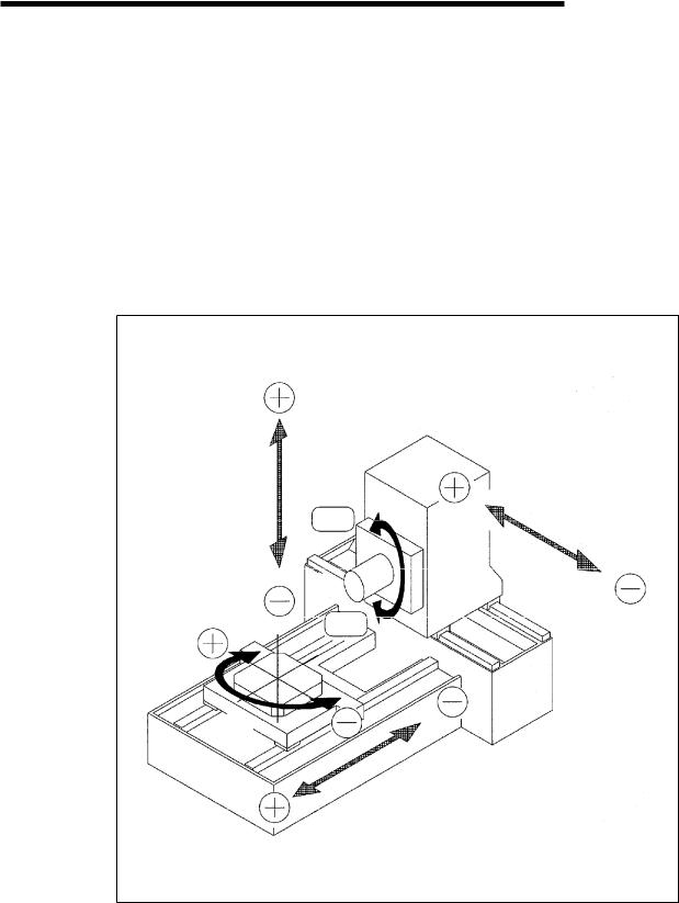
The number of NC controllable axes is 4, and 3 axes can be controlled simultaneously: these NC control axes are X axis - longitudinal movement of column, Y axis - vertical movement of spindle head, Z axis - transverse movement of table, and B axis - table rotation.
Spindle rotation can be set steplessly by the use of AC servo motor.
Y-axis
CW
X-axis
Spindle
CCW
B-axis
Z-axis
2-1
2. MACHINE OUTLINE
FH550SX/630SX
2.2 Controlled axis
Y-axis
X-axis
Z-axis
Axis |
Traveling direction |
|
Min. command |
|
Rapid traverse rate |
Cutting speed (mm/min) |
|
increment |
|
(m/min) |
|||
|
|
|
|
|
||
|
|
|
|
|
|
|
X |
Longitudinal |
|
1/1000 mm |
|
60 m/min |
1~30,000 |
movement of column |
|
|
||||
|
|
|
|
|
|
|
|
|
|
|
|
|
|
Y |
Vertical movement of |
|
1/1000 mm |
|
60 m/min |
1~30,000 |
spindlehead |
|
|
||||
|
|
|
|
|
|
|
|
|
|
|
|
|
|
Z |
Transverse movement |
|
1/1000 mm |
|
60 m/min |
1~30,000 |
of table |
|
|
||||
|
|
|
|
|
|
|
|
|
|
|
|
|
|
B |
NC table rotation |
|
1/1000•‹ |
|
90ø/2sec. |
------- |
|
|
|
|
|
|
|
1•‹ table rotation |
|
1•‹ |
|
90ø/2sec. |
------- |
|
|
|
|
||||
|
|
|
|
|
|
|
Spindle rotating speed (min-1)
Standard |
S35~S6,000 |
|
|
2-2

2. MACHINE OUTLINE
FH550SX/630SX
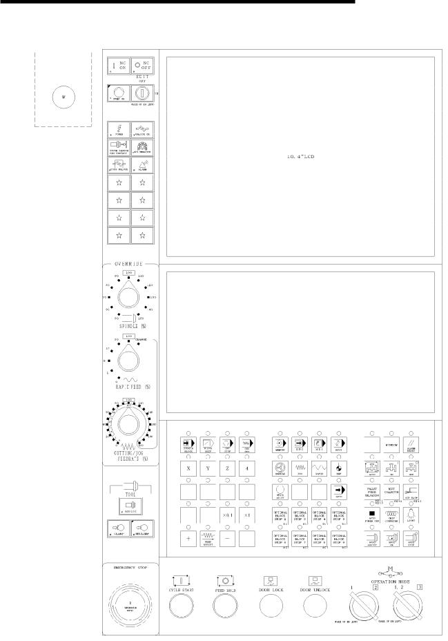
2.3 Operation Panel
2.3.1 Machine Controls Description
This machine has Main Operation Panel and other operation panels of Handle Feed Operation,Tool Magazine, Pallet Change Operation and Chip Conveyor Operation.
2-3 |
2. MACHINE OUTLINE
FH550SX/630SX
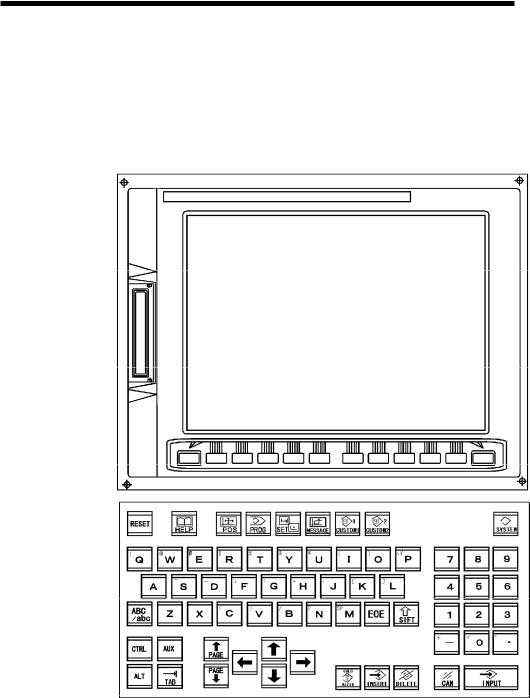
2.3.2 Main Operation Panel
2.3.2.1 NC Operation Panel
2-4
2. MACHINE OUTLINE
FH550SX/630SX
|
Key Name |
Description |
|
|
|
|
|
|
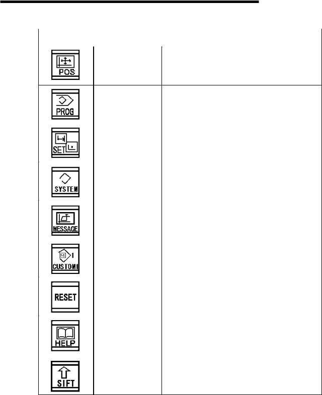
Press this to display the position display screen.
POS key
PROG key |
The viewing and edit of a program which are |
|
registered into memory are performed. |
||
|
|
|
OFFSET |
A viewing and setup of the amount of tool offsets, |
|
the amount of workpiece zero offsets, a macro |
||
SETTING key |
frequency, tool-life data, etc. are performed. |
|
|
|
|
SYSTEM key |
Press this to display the system screen. |
|
A viewing and setup of a parameter, a pitch error |
||
|
||
|
compensation, self-diagnostics data, etc. are |
|
|
performed. |
|
|
|
|
MESSAGE key |
A viewing of an alarm message, PC alarm |
|
message, and alarm hysteresis is performed. |
||
|
||
|
|
|
CUSTOM key |
OP supporter screen is displayed. |
|
|
||
|
|
|
RESET key |
This button is pushed to reset an NC unit for a |
|
cancel release of an alarm etc. |
||
|
||
|
•E If a butt oni s pushe, NC will be reset and it will |
|
|
be in an initial state. |
|
|
|
|
HELP key |
This key is used to request display for such details |
|
as control method and alarm contents generated in |
||
|
||
|
CNC when MDI control method is not sure. |
|
|
|
|
SHIFT key |
The address key by which two letters were printed |
|
is in one key. A letter can be changed and |
||
|
||
|
inputted if a shift key is pushed. When a lower |
|
|
right letter can be inputted, ? ^ ?is displayed on a |
|
|
screen. |
2-5

2. MACHINE OUTLINE
FH550SX/630SX
|
Name |
Description |
|
|
|
|
|
|
|
ALTER key |
This is a key to change the data on the cursor of the |
|
data display area. |
|
|
|
|
|
|
|
|
INSERT key |
This is a key to insert the data of the data input |
|
area. |
|
|
|
|
|
|
|
|
DELETE key |
This is a key to delete on the cursor of the data |
|
display area. |
|
|
|
|
|
|
|
|
INPUT key |
The data which pushed and inputted the address or |
|
the numerical keypad are inputted into a buffer, and |
|
|
|
|
|
|
are displayed. "INPUT" key is pushed to set to an |
|
|
offset air register etc. the information inputted into |
|
|
the key input buffer. |
|
|
It is equivalent to the input of a softkey and |
|
|
whichever may be used. It is used also for |
|
|
handling of moving a folder on a program list |
|
|
screen. |
|
|
|
|
CAN key |
This is a key to delete one letter of the data in data |
|
input area. |
|
|
|
|
|
|
The letter edit mode becomes the operation of a |
|
|
backspace. |
|
|
|
|
PAGE change over |
This is a key to change the page. |
|
ø The page to be pressed by key is changed to the |
|
|
key |
|
|
previous page or the next page. |
|
|
|
|
|
|
|
|
Cursor shifting key |
This is a key to move the cursor. |
|
ø A push on a key moves cursor to the order of right |
|
|
|
|
|
|
and left, and a reverse direction. |
|
|
ø In a small partition unit, it moves to the right |
|
|
direction and a reverse direction. |
|
|
|
|
Cursor shifting key |
This is a key to move the cursor. |
|
ø A push on a key moves cursor to the order of |
|
|
|
|
|
|
upper and lower, and a reverse direction. |
|
|
ø In a large partition unit, it moves to the right |
|
|
direction and a reverse direction. |
|
|
|
2-6
2. MACHINE OUTLINE
|
|
|
|
FH550SX/630SX |
|
|
|
|
|
|
|
|
|
|
|
|
|
|
|
|
|
Name |
Description |
|
|
|
|
|
|
|
|
|
|
|
|
|
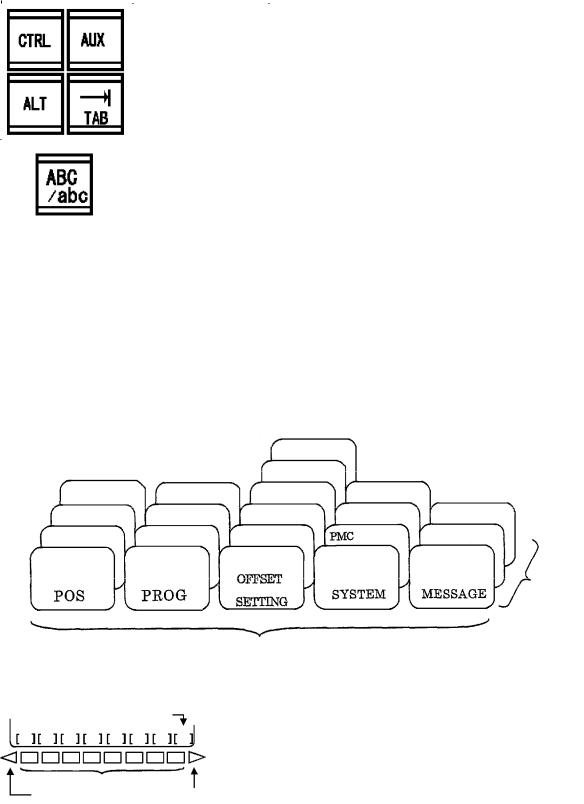
Personal computer |
It is used by the personal computer function of |
|
|
|
function key |
310i/310iS. |
|
|
|
|
|
|
|
|
Upper case/Lower |
The upper case/lower case at the time of an |
|
|
|
case |
alphabet input are switched. |
|
|
|
Change-over key |
|
|
|
|
|
|
|
(1)By pushing the function key on the console panel, the soft key for chapter selection belonging to the function is displayed on a screen.
(2)A push on one of the soft keys for chapter selection displays the screen of the chapter. A chapter key is pushed when the soft key of the chapter which you want to display is not displayed.
Screen configuration image
A screen structure changes with some specification of a machine.
|
|
Operation panel |
|
|
|
Life management |
|
Machine |
Check |
Macro variable |
|
Relative |
Monitor |
Setting |
|
Absolute |
List |
Work offset |
|
General |
Program |
Tool offset |
Parameter |
Message
Alarm
Chapter select soft key
Function key
Chapter
|
Soft key |
Function |
Operation |
menu key |
menu key |
(3)When the screen of the chapter which you want to display is displayed, a menu key is pushed. And the softkey of the description to operate is displayed.
(4)A chapter key is pushed to return to the softkey for chapter selection.
The above is the viewing procedure of a common screen. An actual viewing procedure changes with each screens. Refer to the operation manual instruction of FANUC for the concrete operating procedure.
2-7
2. MACHINE OUTLINE
FH550SX/630SX
2.3.2.2 Machine Operation Panel
2-8
2. MACHINE OUTLINE
|
|
|
|
FH550SX/630SX |
|
|
|
|
|
|
|
|
|
|
|
|
|
|
|
|
|
Name |
Function & Description |
|
|
|
|
|
|
|
|
|
|
|
|
|
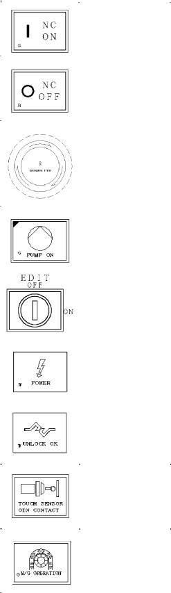
NC ON |
This button is used to supply electric power to the NC device. |
|
|
|
button |
After pushing this button, LCD screen gets display in about |
|
|
|
(Green) |
10 sec. NC device is thus ready to go. |
|
|
|
|
|
|
|
|
NC OFF |
This button is used to shut electic power down to NC device. |
|
|
|
button |
After pushing this button, LCD screen turns off, NC device |
|
|
|
(White) |
has no electric power. Never push this button when |
|
|
|
|
machining or editing is active. |
|
|
|
|
|
|
|
|
EMERGENCY |
This button is used to shut off machine power and hydraulics. |
|
|
|
STOP |
After pushing this button, machine preparatory circuits are |
|
|
|
button |
shut off, [PUMP ON] turns off, and all motions stop. |
|
|
|
(Red) |
•E This button is locked at pressed state upon activatio. |
|
|
|
|
•E Turn to arrowed direction(CW) to be released. |
|
|
|
|
|
|
|
|
PUMP ON |
This button prepares the machine for operation. |
|
|
|
button, lamp |
•E Pressing this button starts the hydraulic pum, lubricating, |
|
|
|
(Green) |
and spindle lubricating pump. |
|
|
|
|
|
|
|
|
EDIT ON/OFF |
This key is used to select edit mode active or not. |
|
|
|
key switch |
•E Select ON positio, then edit mode is active. |
|
|
|
|
•E Select OFF positio, then edit mode is not active. |
|
|
|
|
|
|
|
|
POWER |
This lamp goes on when turning ON the handle of the |
|
|
|
lamp |
no-fuse breaker on the control cabinet. |
|
|
|
(White) |
|
|
|
|
|
|
|
|
|
UNLOCK OK |
This lamp is used to release the lock of the operator door. |
|
|
|
lamp |
|
|
|
|
(White) |
|
|
|
|
|
|
|
|
|
TOUCH SENSOR |
This lamp goes on when detecting the contact between the |
|
|
|
OIN CONTACT |
spindle (tool) and the table (fixture, workpiece). |
|
|
|
lamp |
|
|
|
|
(Orange) |
|
|
|
|
|
|
|
|
|
M/G OP |
This lamp goes on when the MANUAL at magazine |
|
|
|
lamp |
operation panel was selected. |
|
|
|
(Orange) |
|
|
|
|
|
|
|
2-9
2. MACHINE OUTLINE
|
|
|
|
|
|
|
|
|
|
FH550SX/630SX |
|||
|
|
|
|
|
|
|
|
|
|
||||
|
|
|
|
|
|
|
|
|
|
||||
|
|
|
|
|
|
|
|
|
|
|
|||
|
|
Name |
|
|
Function & Description |
|
|
||||||
|
|
|
|
|
|
|
|
|
|||||
|
|
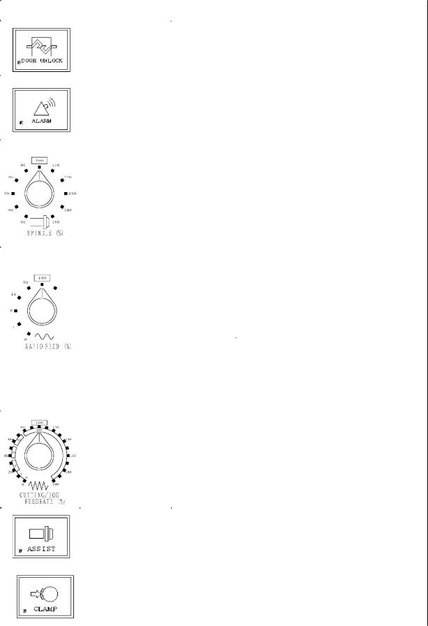
DOOR UNLOCK |
This lamp goes on when releasing the electromagnetic type |
|
|||||||||
|
|
lamp |
interlock at operator?s door, magazine door and APC door. |
|
|
||||||||
|
|
(Red) |
|
|
|
|
|
|
|
|
|
|
|
|
|
|
|
|
|
|
|
|
|
||||
|
|
ALARM |
This lamp goes on when any abnormal is occurred. |
|
|
||||||||
|
|
lamp |
This lamp blinks at alarm. |
|
|
|
|
|
|||||
|
|
(Red) |
This lamp turns off when releasing the alarm or warning |
|
|||||||||
|
|
|
condition. |
|
|
|
|
|
|
|
|||
|
|
|
|
|
|
|
|
|
|
||||
|
|
SPINDLE |
•E |
Thi s s wit ch can changet he speedfr o m50t o 150 %of t he |
|
||||||||
|
|
OVERRIDE |
|
programmed rotation speed (S command). But in tapping |
|
||||||||
|
|
selection switch |
|
cycle (G84), the spindle speed is fixed in 100%. |
|
|
|||||||
|
|
(Gray) |
•E |
Whent he spi ndl e speedi s max. t he speedi sfi xedt o |
max. |
|
|||||||
|
|
|
|
even if up the speed by the override switch. |
|
|
|||||||
|
|
|
•E |
Whent he spi ndl e speedi s mi n. t he speedi s fi xedt o |
mi n. |
|
|||||||
|
|
|
|
even if down the speed by the override switch. |
|
|
|||||||
|
|
|
|
|
|
|
|
|
|||||
|
|
RAPID FEED |
This selection switch changes the feed switch for G00 and |
||||||||||
|
|
OVERRIDE |
G28, namely rapid feed and Zero-return speed. |
|
|
||||||||
|
|
selection switch |
|
|
|
|
|
|
|
|
|
|
|
|
CHANGE |
|
|
% |
|
FH550SX |
|
|
FH630SX |
|
|
|
|
|
(Gray) |
|
|
|
|
|
|
|
|
||||
|
|
|
|
0% |
|
0 mm/min |
|
|
0 mm/min |
|
|
|
|
|
|
|
|
|
1% |
|
600 mm/min |
|
|
600 mm/min |
|
|
|
|
|
|
|
|
5% |
|
3000 mm/min |
|
|
3000 mm/min |
|
|
|
|
|
|
|
|
10% |
|
6000 mm/min |
|
|
6000 mm/min |
|
|
|
|
|
|
|
|
50% |
|
30000 mm/min |
|
30000 mm/min |
|
|
|
|
|
|
|
|
|
100% |
|
60000 mm/min |
|
60000 mm/min |
|
|
|
|
|
|
|
* CHANGE |
|
|
|
|
|
|
|
|||
|
|
|
|
In case of turn to CHANGE position |
|
|
|
|
|
||||
|
|
|
|
It operates according to the % of CUTTING/JOG |
|
|
|||||||
|
|
|
|
FEEDRATE. |
|
|
|
|
|
|
|
||
|
|
|
|
An inner side follows "RAPID FEED", an outside follows |
|
|
|||||||
|
|
|
|
"CUTTING FEED OVERRIDE", and it operates. |
|
|
|||||||
|
|
CUTTING/JOG |
It is a switch for modifying 0 to 200% of a rate to the rate of |
|
|||||||||
|
|
FEEDRATE |
CUTTING FEED maximum speed (30000mm/min) and JOG |
|
|||||||||
|
|
override selection |
FEED maximum speed (10000mm/min). |
|
However, the midst |
|
|||||||
|
|
switch |
of a tap cycle is fixed to 100%. |
|
|
|
|
|
|||||
|
|
(Gray) |
Moreover, X1 changes by JOG select button, and a cutting |
|
|
||||||||
|
|
|
feed speed changes by X0.1. |
|
|
|
|
|
|||||
|
|
|
In X1, it is clamped by the cutting feed maximum speed is |
|
|
||||||||
|
|
|
110% or more. |
|
|
|
|
|
|
|
|||
|
|
|
|
|
|
|
|
|
|||||
|
|
ASSIST |
This button is used for effective the spindle tool "CLAMP" and |
|
|||||||||
|
|
button, lamp |
"UNCLAMP" buttons. |
|
|
|
|
|
|
|
|||
|
|
(White) |
•E" CLA MP" and " UNCLA MP" butt oni s pr essed, pr essi ngt hi s |
||||||||||
|
|
|
|
button. |
|
|
|
|
|
|
|
||
|
|
|
|
|
|
|
|
|
|
||||
|
|
CLAMP |
This button is used for attaching a tool to the spindle. |
|
|
||||||||
|
|
button, lamp |
•E It beco mes eff ecti ve, |
whent hel a mp of " HANDLE", "J OG", |
|||||||||
|
|
(White) |
|
"RAPID" or, and "REF" is on and "ASSIST" button is |
|||||||||
|
|
|
|
pressed. |
|
|
|
|
|
|
|
||
|
|
|
•E |
If t he butt oni s pr essed, t he spi ndl e will be cl a mped and air |
|||||||||
|
|
|
|
will be stopped. |
|
|
|
|
|
|
|
||
|
|
|
|
2-10 |
|
|
|
|
|
|
|
|
|

2. MACHINE OUTLINE
|
|
|
|
FH550SX/630SX |
|
|
|
|
|
|
|
|
|
|
|
|
|
|
|
|
|
Name |
Function & Description |
|
|
|
|
|
|
|
|
UNCLAMP |
This button is used for removing a tool from the spindle. |
|
|
|
button, lamp |
•E It becomes effective, when the lamp of "HANDLE", "JOG", |
|
|
|
(White) |
"RAPID" or, and "REF" is on and "ASSIST" button is |
|
|
|
|
pushed. |
|
|
|
|
ø If the button is pressed, the spindle will be unclamped and |
|
|
|
|
air will be come out. |
|
|
|
|
ø When demounting a tool from a spindle, before pressing |
|
|
|
|
the button, the tool is clamped certainly. When a |
|
|
|
|
clamping is inadequate, the tool falls. |
|
|
|
SINGLE BLOCK |
This button SINGLE BLOCK makes a block stop at |
|
|
|
button, lamp |
MEMORY, TAPE and/or MDI operations. |
|
|
|
(Green) |
•E When the SINGLE BLOCK lamp turns on, and the butto |
|
|
|
|
[CYCLE START] is pressed, the specified block is |
|
|
|
|
executed and the cycle stops. |
|
|
|
|
•E When the SINGLE BLOCK lamp turns off, and the butto |
|
|
|
|
[CYCLE START] is pressed, the rest of the program is |
|
|
|
|
executed accordingly. |
|
|
|
|
•E When the SINGLE BLOCK button is pressed, the lam |
|
|
|
|
turns on or off. |
|
|
|
BLOCK SKIP |
This BLOCK SKIP button is used to disregard the block, |
|
|
|
button, lamp |
when command line starts with / (slash), is MEMORY, TAPE |
|
|
|
(Green) |
and/or MDI operation. |
|
|
|
|
ø When the BLOCK SKIP lamp turns on, the block with / |
|
|
|
|
(slash) is neglected. |
|
|
|
|
ø When the BLOCK SKIP lamp turns off, the block with / |
|
|
|
|
(slash) is executed. |
|
|
|
|
ø When the BLOCK SKIP button is pressed, this lamp turns |
|
|
|
|
on or off. |
|
|
|
OPT STOP |
This button is used to stop at the block of ?M01 signal in the |
|
|
|
button, lamp |
MEMORY, TAPE or MDI operation. |
|
|
|
(Green) |
ø When the lamp is lit, the operation stops at the block of |
|
|
|
|
?M01 signal. |
|
|
|
|
ø When the lamp is not lit, the operation stops at the block of |
|
|
|
|
?M01 signal. |
|
|
|
|
ø When pressing the button, this lamp is lit or not lit. |
|
|
|
DRY RUN |
This DRY RUN button is used to move a feed unit with JOG |
|
|
|
button, lamp |
speed instead of cutting speed in MEMORY, TAPE and/or |
|
|
|
(Green) |
MDI operation. |
|
|
|
|
ø When the DRY RUN lamp turns on, the feed unit moves |
|
|
|
|
with JOG speed instead of cutting speed. |
|
|
|
|
ø When the DRY RUN lamp turns off, the feed unit moves |
|
|
|
|
with cutting speed. |
|
|
|
|
ø When the DRY RUN button is pressed, the lamp turns on |
|
|
|
|
or off. |
|
|
|
X, Y, Z, 4-axis (axis |
This button is used to choosing JOG, RAPID FEED, ZERO |
|
|
|
select) |
RETURN, and MOVE AXIS. |
|
|
|
button, lamp |
ø The axis which the lamp has turned on is effective. |
|
|
|
(Green) |
|
|
|
|
|
|
|
|
|
X0.1,X1 |
This button is used to changes the magnification of the |
|
|
|
button, lamp |
maximum speed (10000mm/min) of JOG feed. |
|
|
|
(White) |
ø When JOG OVERRIDE is 100% |
|
|
|
|
X0.1 •E•E•E•E•E 1000m |
|
|
|
|
X1 •E•E•E•E•E 10000m |
|
|
|
|
|
|
2-11
 Loading...