


3000C
FANUC
3000C
1.
2.
OUTLINE
SPECIFICATIONS
2.
2.
2.3
2.4
1
2
Basic
Basic
Additional
Outer
Unit
Option
View
CONTENTS
,
...
Options
.
OPERATOR’S
FUJITSU
..
FANUC
MANUAL
LTD
;
1
3
3
7
8
13
3.
1
PROGRAMMING
3.
3.
3.
3.4
3.
3.
3.7
3.8
3.9
3.
3.
3.11.1
3.11.2
3.11.3
1
2
3
5
6
10
11
General
Process
Tape
Increment
Buffer
Absolute
Maximum
Tape
Address
Function
Feed
Format
Code
Function
Rapid
1
-Digit
4
-Digit
,
.
Sheet
System
Register
and
Programmable
Codes
Codes
Traverse
F-Code
F-Code
. .
.
(Buffer)
Incremental
Speed
Unit
Unit
Programming
Dimensions
15
.
.
15
15
17
18
20
20
21
22
22
24
25
25
26
27
B-5
520E/06
1
3.
12
Preparatory
Function
(G
Function)
30
3.
3.
3.
3.
3.
3.
3.
3.12.
3.
3.
3.
3.
3.
3.
3.
3.
3.
3.
3.
3.
3.
3.
3.
3.
3.
3.
3.23
3.
3.25
12.
12.
12.
12.4
12.
12.
12.
12.
12.
12.11
12.
12.
12.
12.
12.
13
14
15
16
17
18
19
20
21
22
24
1
Positioning
Linear
2
Circular
3
Dwell
Circle
5
6
Helical
G15),
7
Plane
8
Programming
9
10
12
13
14
Zero
Cutter
Tool
Tool
Canned
Absolute
G91)
Programming
15
Initial
16
D
Spindle
Tool
B
Miscellaneous
Automatic
Optional
Absolute
Mirror
Sequence
Label
Sub
Programming
H
and
Function
Function
Skip
Tape
-Speed
Interpolation
Interpolation
(G04)
Cutting
Interpolation
B(G02,G03)
Selection
Return
Compensation
Offset
Offset
Cycles
and
Level
Functions
Function
(T
Acceleration
Block
Rewind
image
Number
Function
Control
Examples
(GOO)
(G12,
Copy
(G27
B
(G43,
A
(G45
(G73,
Incremental
of
and
Function)
Function
Skip
Stop
Display
,
(G17
(G25)
,
G28,
to
Absolute
R
point
(S
(M
and
&
Reset
and
(G01)
(GO
G13)
Helical
G18,
G29)
(G38
G44,
G48)
G76,
Level
Function)
Function)
Deceleration
&
Search
Control
.....
2,
GO
3)
.
Interpolation
G19)
.
G42)
to
G49)
G80
Programming
Zero
In/Out
G89)
to
Point
(G98
and
.
(G90
(G92)
G99)
A(G14,
and
•
-
..
.
32
34
36
40
41
42
46
46
49
51
63
66
76
91
91
93
94
95
96
97
98
99
101
103
104
105
106
108
111
4.
:
;
i
1
OPERATION
4.1
4.1.1
4.1.2
4.1.
MDI
3
4.1.4
2
4.
4.
4.4
4.
3
5
4.5.
4.
4.5.3
5.
Position
1-Digit
Built-in
Tape
1
2
DPL
&
Display
Switch
Display
Manual
Display
F-Code
Type
Reader
Tape
Tape
Procedure
Reader
Reader
Unit
Section
and
Unit
Data
Button
Section
Input
Unit
Unit
Manual
without
with
of
Setting
Section
........
(MDI)
Operator's
Reels
Reels
NC
an
..
Section
.....
Tape
..
Panel
116
;
116
116
118
120
129
148
150
150
151
151
154
158
4
4.7
Punch
6
.
Procedure
Operator's
of
Panel
Function
161
162
4.7.1
4.7.2
4.7.3
4.7.4
4.7.5
4.7.6
4.7.7
4.7.8
4.7.9
4.7.10
4.7.11
4.7.12
4.7.13
4.7.14
4.7.15
4.7.
4.7.
4.7.
4.7.
4.7.20
4.7.21
4.7.22
4.7.23
4.7.24
16
17
18
19
MODE
CYCLE
FEED
JOG
RAPID
DRY
OPTIONAL
F4
JOG
EMERGENCY
SINGLE
ZERO
Lamps
BLOCK
DISPLAY
Z-AXIS
MANUAL
SCALE
AUXILIARY
HANDLE
MANUAL
SEARCH
OVERRIDE
POWER
2ND
SELECT
HOLD
&
STEP
TRAVERSE
RUN
FEED
FEED
RETURN
L.S.
START
BLOCK
RETURN
FEED
RETURN
START
ON/OFF
Switch
Button
Button
Button
Switch
BLOCK
RATE
RATE
OVERRIDE
Dial
STOP
Switch
Switch
Switch
LOCK/MACHINE
NEGLECT
ABSOLUTE
Switch
FUNCTION
AXIS
and
PULSE
CANCEL
REMOVE
SELECT
MULTIPLY
Button
Button
Switch
...
SKIP
Button
and
Switch
Switch
Switch
..
.
.
.....
Switch
Switch
LOCK
Dial
ZERO
LOCK
Switch
.
Switch
Switch
.
.
.
.
.
POSITION
Switch
..
162
164
165
166
167
167
168
168
169
170
171
173
174
177
178
179
181
181
182
183
183
183
1
83
183
5.
*
6.
OPERATIONAL
1
5.
2
5.
5.
3
5.4
5
5.
6
5.
7
5.
5.8
5.9
10
5.
11
5.
MAINTENANCE
1
6.
2
6.
3
6.
Preparation
Power
Turning
Setting
Manual
Setting
Tape
NC
Manual
Operation
Operation
Preparation
Turning
Daily
P
ow
er
Fault
PROCEDURE
and
Inspection
....
.....
on
Power
T
ape
a
Operation
Zero
the
Point
Operation/Memory
Operation
MDI
by
the
by
before
Off
Power
Maintenance
Fuses
Causes
and
during
Unit
MDI
Remedies
before
. .
NC
.
Call
Tape
NC
Off
.....
during
Turning
Turning
.
Operation
Operation
Tape
Power
on
.
.
.
Operation
..........
......
.
185
.
185
185
185
.
188
190
191
192
192
.
.
192
192
192
193
193
194
195
APPENDIXES
Appendix
Appendix
Appendix
Appendix
Appendix
Appendix
Appendix
1
2
3
List
Range
of
Nomographs
1
3.
Tape
of
3.2
4
5
6
7
Preparation
How
to
RESET
State
and
and
Operation
Join
Codes
Various
Error
Circular
Tool
of
NC
Display
in
Path
NC
Tape
Commands
the
Radius
Cutting
a
at
Corner
Tape
of
Control
Values
Direction
in
Unit/Mode
201
202
205
205
208
216
218
219
Selection
220
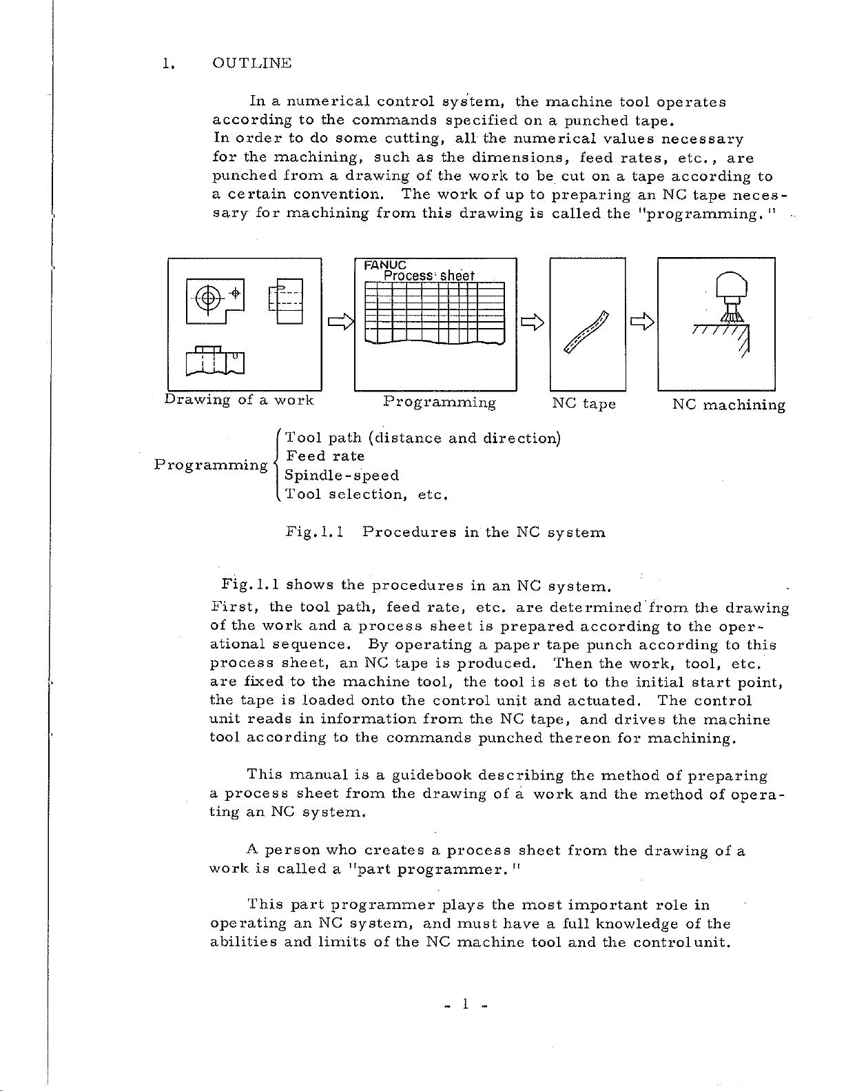
1.
OUTLINE
In
according
order
In
for
the
punched
certain
a
sary
for
a
numerical
to
the
to
do
machining,
from
convention.
machining
commands
some
a
drawing
ccmtrol
cutting,
such
The
from
FANUC
Process;
as
of
this
system,
specified
all
the
dimensions,
the
work
work
drawing
sheet
the
of
the
on
numerical
to
be
up
to
is
machine
punched
a
feed
cut
preparing
called
values
on
operates
tool
tape.
rates,
tape
a
an
the
"programming.
necessary
etc.,
according
tape
NC
are
neces¬
to
"
-
ura
Drawing
P
rog
(id
ramming
Fig.
First,
of
the
ational
process
are
the
unit
tool
d
of
work
a
1.1
the
work
sequence.
fixed
tape
reads
according
Tool
Feed
path
rate
Spindle-speed
1.1
tool
and
to
the
loaded
in
information
selection,
the
path,
a
an
machine
to
the
Tool
Fig.
shows
sheet,
is
Programming
(distance
Procedures
procedures
feed
process
By
operating
tape
NC
onto
the
commands
etc.
rate,
sheet
tool,
control
from
and
is
produced.
direction)
in
the
in
an
etc.
is
paper
a
the
tool
unit
the
punched
NC
NC
are
prepared
is
and
NC
tape,
NC
tape
system
system.
determined
according
tape
punch
Then
set
thereon
the
to
actuated.
and
the
drives
for
o
from
to
according
work,
initial
The
machining.
77777
NC
the
the
tool,
start
control
the
$
machining
drawing
oper¬
to
this
etc.
point,
machine
This
process
a
an
ting
A
work
This
operating
abilities
NC
person
is
manual
sheet
called
part
an
and
system.
who
a
programmer
NC
limits
is
from
creates
"part
system,
of
guidebook
a
the
drawing
programmer.
the
a
and
NC
process
plays
must
machine
1
describing
of
a
sheet
"
most
the
have
work
a
tool
the
method
and
from
important
full
knowledge
and
the
the
the
method
drawing
role
control
of
preparing
of
of
in
the
unit.
opera¬
of
a
For
example,
he
must
select
(1)
select
(2)
effectively
(3)
(4)
(5)
the
give
point,
effectively
Also,
high-accuracy
tool,
Setting
to
setting
addition
the
(1)
resetting
Giving
(2)
(3)
Daily
such
the
tool
a
optimum
use
operator
,
etc.
use
operator
the
products,
the
usual
the
Cutter
the
because
instructions
maintenance
path
spindle
M
the
information
the
Canned
of
pay
operations
tape,
Compensation
the
of
about
(cleaning
as
to
function
NC
an
attention
operating
tool
regrinding
reduce
speed,
or
on
Cycle,
system
(loading
wear,
and
the
tool
and
function,
G
the
tool
etc.
must,
to
the
and
the
control
amount
etc.)
the
inspection)
machining
feed
change,
order
in
following
unloading
panel,
(requiring
tool
time,
rate,
machine
points
the
etc.)
the
to
work
produce
setup
in
and
periodical
The
front
its
Particularly
doors
outside
centers,
the
positioning
centers,
(including
This
machine
The
operator
and
enter
air
manual
milling
FANUC
and
etc,
back
in
a
that
tool
continuous
and
does
doors
usual
of
directly
discusses
machines,
builder
C
3000
used
not
need
open
operation,
the
tape
into
the
etc.
to
as
NC
are
cutting
FANUC
to
except
he
reader)
it.
equipment
Refer
which
equipped
for
DC
operate
for
rather
options
milling
servo
the
the
closed
with
the
to
with
motor
equipment
NC
maintenance.
operates
so
as
options
description
be
can
2-to
machines,
used
4-axis
series
with
it
not
for
machining
as
with
the
to
let
machining
issued
in
practice.
the
the
by
servo.
2
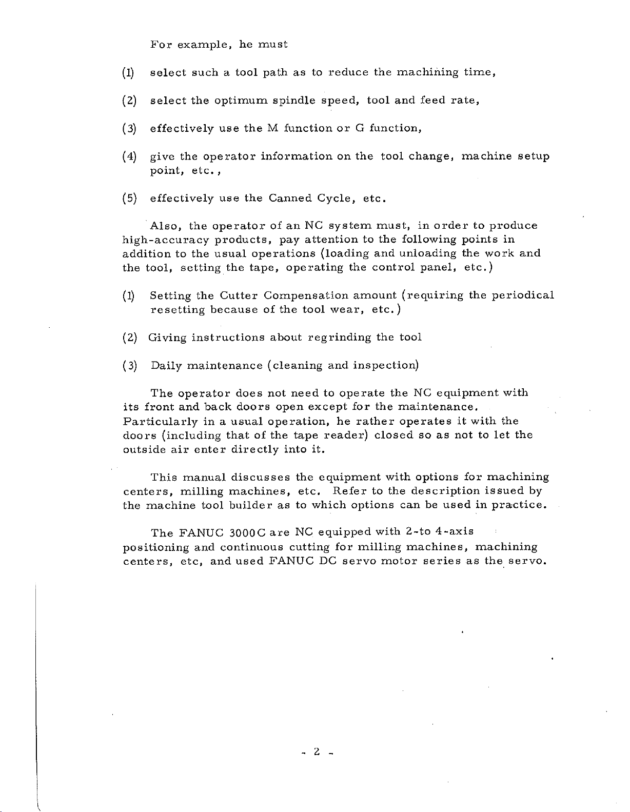
2.
SPECIFICATIONS
2.1
Item
(1)
(2)
(3)
(4)
(5)
(6)
Basic
Controlled
The
number
controllable
Maximum
dimension
Tape
Tape
Increment
Unit
Name
axes
of
axes
programmable
command
format
system
simultaneously
axes
3
options)
axes
2
additional
(4
axes
additional
manual
not
controlled
See
Section
-channel
8
RS-227)
See
Section
See
Section
Spe
(4
axes
_
axes
(3
options)
linear
for
options)
operation,
black
cifications
with
for
at
3.7.
3.3.
3.4.
additional
positioning
interpolation
In
three
time
a
paper
tape
case
axes
.
with
with
of
are
(EIA
(?)
(8)
(9)
(10)
(11)
(12)
EIA
code
ISO
code
Absolut
programming
Positioning
Linear
4-digit
Automatic
deceleration
/
e/lnc
interpolation
F-code
input
input
remental
feed
acceleration
See
Appendix
This
permits
Absolute
mixedly
Preparatory
The
identifies
Incremental
respectively.
permits
GOO
each
for
speed.
specifies
G01
to
tool
straight
end
See
See
be
point.
Section
Section
and
Incremental
one
in
the
programming,
individual
axis
controlled
line
up
3.11.
3.18.
1
.
specifying
block
function
Absolute
the
at
the
movement
to
a
the
dimensions
of
tape.
(G90,
the
and
positioning
Rapid
along
programmed
Traverse
a
of
G91)
a
(13)
Override
A
override
ment
a
panel
3
-
-
of
rotary
.
10%
switch
can
in
a
be
range
on
effected
0
the
operator's
to
in
incre¬
200%
by
Item
(14)
Name
Programming
Zero
point
of
Absolute
permits
G92
ment
the
current
specified
such
Specifications
setting
a
coordinate
position
position
within
of
a
the
system
tool
equip¬
is
that
a
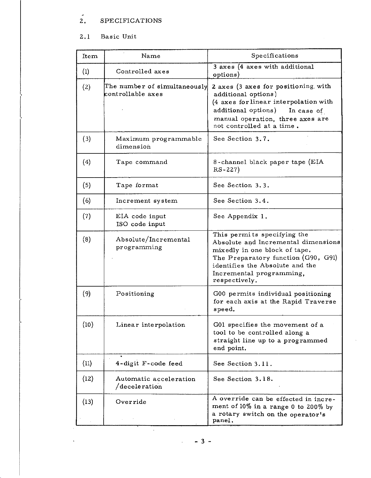
(15)
(16)
(17)
(18)
(19)
(20)
Miscellaneous
Backlash
Single
Label
Mirror
block
skip
image
/Remote
Interlock
function
compensation
mirror
image
This
specifies
M99.
this
By
pensated
a
in
range
This
executing
tape.
This
tape
place,
up
the
Symmetrical
with
is
function
or
the
to
tape.
respect
function.
This
axis
function
independently.
function,
in
of
a
function
only
for
ignores
and
first
the
backlash
increments
1
to
255
one
used
is
starting
EOB
cutting
to
any
stops
two-digit
pulses.
of
reading
block
for
the
the
information
code
can
axis
feed
the
is
one
of
of
naming
tape
in
be
performed
by
MOO
com¬
pulse
and
NC
at
reading
this
for
to
the
any
each
(21)
(22)
(23)
(24)
(25)
Dwell
Machine
Auxilliary
Display
Optional
lock
lock
Block
function
Skip
lock
G04
a
This
the
automatic
This
and
This
position
machine
This
skipping
punched
4
permits
specified
is
position
function
B
code
is
is
a
function
or
to
a
function
display
tool
function
a
block
a
with
stopping
period
display
manual
inhibits
Machine
is
"/"
of
time.
of
operating
unit
operation.
output
of
stopping
unit
while
operating
of
selectively
NC
of
(slash).
the
tape
feed
during
of
the
normally.
for
M,
the
only
an
S,
T

Item
(26)
(27)
(28)
(29)
Manual
feed
JOG
STEP
MDI
feed
feed
h
Name
rapid
DPL
traverse
This
tool
TRAVERSE
in
by
This
tool
kept
mode
This
tool
when
in
SELECT
See
function
rapidly
the
the
function
while
pushed
function
to
the
Section
manual
MODE
by
XI,
the
step
Specifications
feed
can
while
button
continuous
SELECT
feed
can
the
JOG/
the
in
MODE
the
can
feed
,
X10
JOG/
feed
switch.
X100
STEP
mode
4.1.1
RAPID
the
is
kept
STEP
manual
SELECT
,
button
by
the
feed
switch.
the
button
the
X1000
the
machine
pushed
mode
machine
is
continuous
switch.
machine
pulses
is
pushed
MODE
(30)
(31)
(32)
(33)
(34)
(35)
Override
Z-axis
cancel
Tool
offset
Sequence
Remote
Remote
cancel
command
A
number
deceleration
power
search
ON/OFF
This
enable
Override
During
operation
can
be
This
for
This
to
number
This
rate
The
by
addition
button
panel.
is
a
feature
search
function
from
power
contact
a
a
made
a
cutter
on
on
the
fix
cycle
command
a
function
length.
any
tape.
outside,
is
signal
to
the
the
4
-digit
to
100%.
operation
to
be
ignored.
of
enables
following
decelerates
turned
POWER
control
F-code
or
the
for
compensating
operater
the
sequence
the
on
and
from
outside
ON/OFF
display
unit
feed
manual
Z-axis
feed
off
in
(36)
Buffer
register
5
-
This
mitting
executed,
ahead
NC
permits
tape.
pulses
during
continuously
between
by
reading
the
one
operation
blocks
block
trans¬
an
by
being
Item
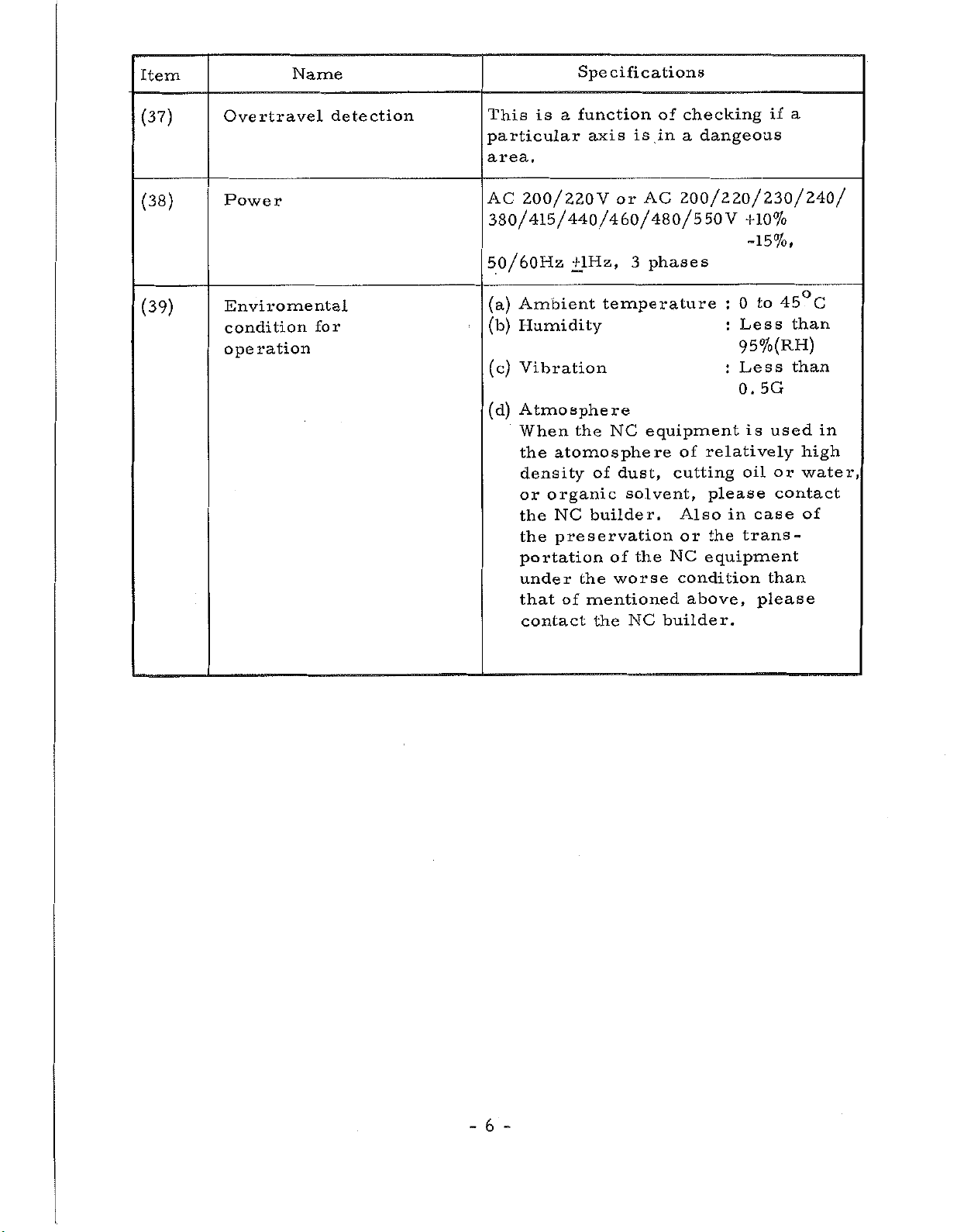
(37)
Overtravel
Name
detection
This
particular
is
area.
Specifications
function
a
axis
a
checking
of
is
in
a
dangeous
if
(38)
(39)
Power
Enviromental
condition
operation
for
AC
200/220V
380/415/440/460/480/550V
or
AC
200/220/230/240/
+10%
-15%,
3
50/60Hz
Ambient
(a)
Humidity
(b)
+lHz,
temperature
phases
:
:
to
0
Less
45°C
than
95%(RH)
5G
is
case
please
than
used
or
contact
than
(c)
Vibration
Atmosphere
(d)
When
the
density
or
the
the
portation
under
that
contact
NC
the
atomo
organic
NC
preservation
of
sphere
of
builder.
of
the
mentioned
the
equipment
dust,
solvent,
the
worse
NC
of
cutting
Also
or
NC
equipment
condition
above,
builder.
Less
:
0.
relatively
oil
please
in
trans¬
the
in
high
water,
of
6
-
-
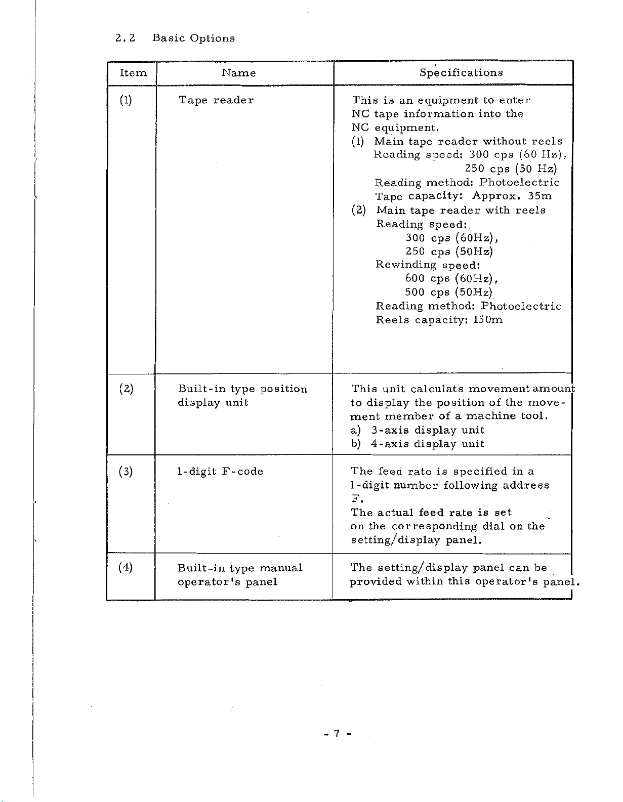
2.2
Basic
Options
Item
(1)
Tape
Name
reader
This
NC
NC
(1)
(2)
is
an
tape
information
equipment.
Main
Reading
Reading
Tape
Main
Reading
tape
capacity:
tape
300
250
Rewinding
600
500
Reading
Reels
Specifications
equipment
reader
speed:
250
method:
reader
speed:
cps
(60Hz),
(50Hz)
cps
speed:
cps
(60Hz)
(50Hz)
cps
method:
capacity:
to
enter
into
the
without
300
cps
cps
Photoelectric
Approx.
with
,
Photoelectric
150m
(60
(50
reels
reels
Hz),
Hz)
35m
(2)
(3)
(4)
Built-in
display
1-digit
Built-in
operator's
type
unit
F-code
type
position
manual
panel
This
to
ment
a)
b)
The
1
-digit
display
-axis
3
4
-axis
feed
calculats
unit
member
rate
number
the
display
display
F.
The
on
actual
the
feed
corresponding
setting/display
setting/
The
provided
within
position
of
is
following
rate
panel.
display
this
movement
machine
a
unit
unit
specified
is
dial
panel
operator's
of
set
move¬
the
tool.
a
in
address
on
the
can
amount
be
panel.
7
-
-
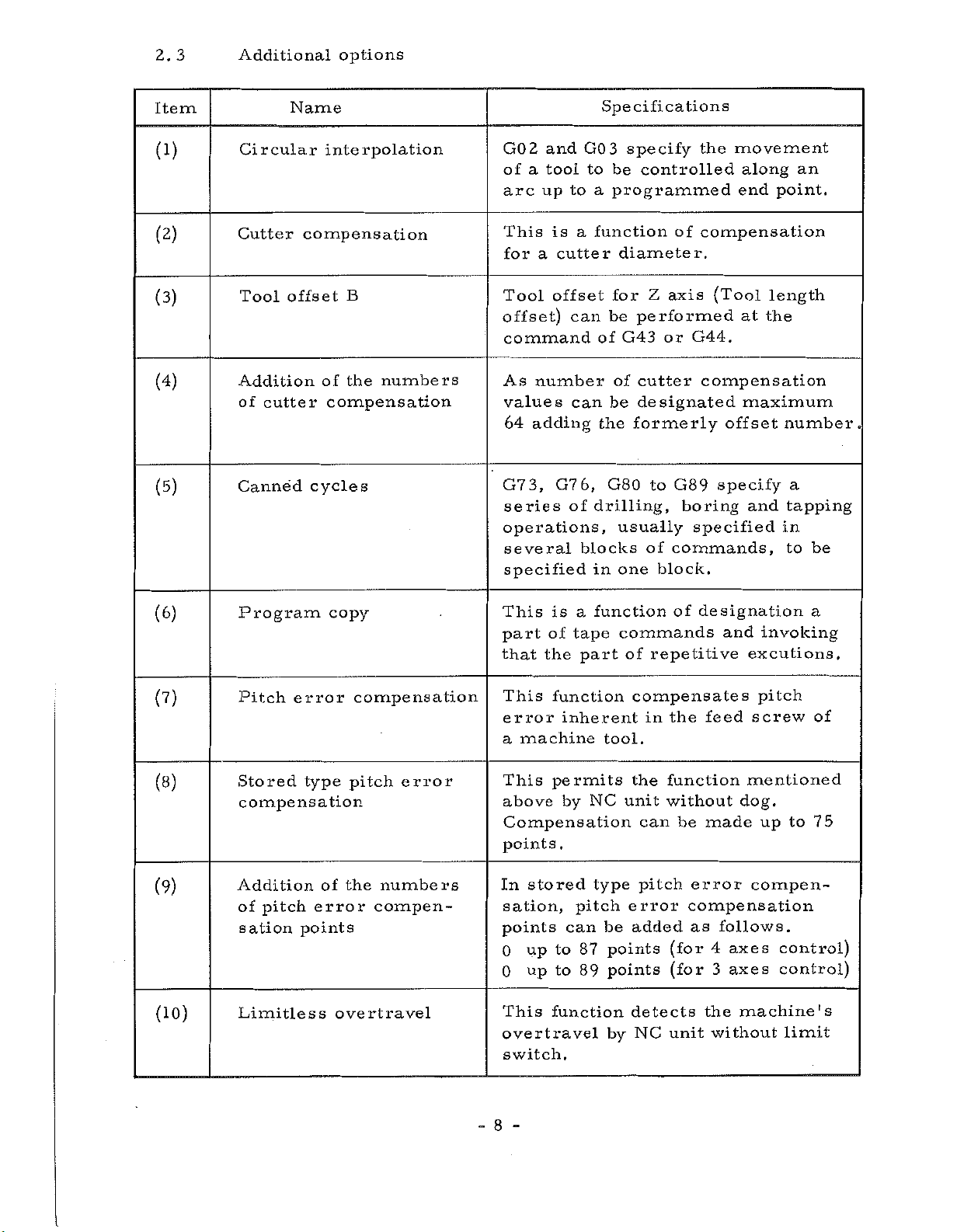
2.
3
Additional
options
Item
(1)
(2)
(3)
(4)
(5)
Circular
Cutter
Tool
Addition
cutter
of
Canned
Name
interpolation
compensation
offset
B
of
the
compensation
cycles
numbers
GO
2
and
of
tool
a
up
arc
This
for
Tool
a
is
cutter
offset
offset)
command
number
As
values
adding
64
3,
G7
series
operations,
several
specified
G7
Specifications
3
GO
to
be
a
to
programmed
function
a
diameter.
for
can
be
G43
of
of
be
can
the
6,
G80
of
drilling,
usually
blocks
in
one
specify
controlled
of
Z
axis
performed
or
cutter
designated
formerly
to
G89
commands,
of
block.
movement
the
along
end
compensation
(Tool
at
G44.
compensation
maximum
offset
specify
boring
specified
and
point.
length
the
number.
a
tapping
in
to
an
be
(6)
(?)
(8)
(9)
(10)
Program
Pitch
Stored
compensation
error
type
Addition
pitch
of
sation
Limitless
error
points
copy
compensation
pitch
the
of
overtravel
error
numbers
compen¬
This
part
that
This
error
a
This
above
Compensation
points
In
sation,
points
0
0
This
overtravel
switch.
is
of
the
function
inherent
machine
permits
by
.
stored
can
to
up
to
up
function
a
tape
part
pitch
87
89
function
commands
of
compensates
tool.
the
NC
unit
type
error
be
added
points
points
detects
by
repetitive
the
in
function
without
can
pitch
(for
(for
NC
unit
of
designation
and
feed
dog.
made
be
error
compensation
as
follows.
axes
4
3
axes
the
machine's
without
invoking
excutions.
pitch
screw
mentioned
to
up
compen¬
control)
control)
limit
a
of
75
8
-
-
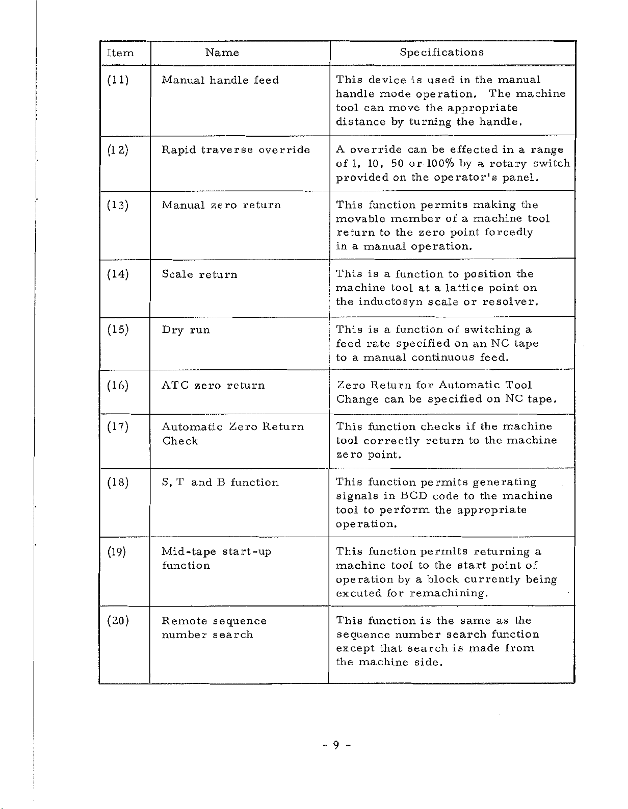
Item
Name
Specifications
(11)
2)
(1
(13)
(14)
(15)
Manual
Rapid
Manual
Scale
Dry
traverse
return
run
handle
zero
feed
override
return
This
handle
tool
can
distance
A
override
1,
of
provided
This
movable
return
a
in
manual
This
machine
inductosyn
the
This
feed
to
a
manual
device
mode
move
by
10,
50
on
function
member
to
is
function
a
tool
function
is
a
rate
is
used
operation.
the
turning
can
or
100%
the
permits
zero
the
operation.
at
scale
specified
continuous
in
appropriate
the
be
effected
by
operator's
of
a
point
to
position
lattice
a
or
of
switching
on
the
manual
The
handle.
rotary
a
making
machine
forcedly
point
resolver.
NC
an
feed.
machine
in
a
panel.
the
tape
range
switch
the
tool
on
a
(16)
(17)
(18)
(19)
(20)
ATC
zero
Automatic
Check
T
S,
Mid
and
-tape
function
Remote
number
return
Zero
B
function
start-up
sequence
search
Return
Zero
Change
This
tool
zero
This
signals
tool
operation.
This
machine
operation
excuted
This
Return
function
correctly
point.
function
to
function
function
sequence
except
the
machine
can
BCD
in
perform
tool
by
for
number
search
that
for
Automatic
be
specified
checks
return
permits
code
the
appropriate
permits
start
the
to
block
a
remachining.
is
the
search
is
side.
on
the
if
to
the
generating
to
the
returning
currently
same
made
Tool
NC
machine
machine
machine
point
the
as
function
from
tape.
a
of
being
-9-
Item
Name
Specifications
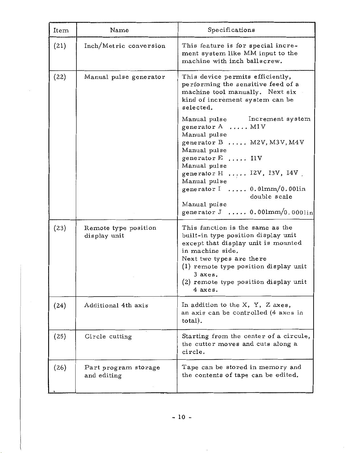
(21)
(22)
Inch/Metric
Manual
pulse
conversion
generator
This
ment
machine
This
performing
machine
kind
selected.
Manual
generator
Manual
feature
system
device
of
generator
Manual
generator
Manual
generator
Manual
generator
Manual
generator
is
with
permits
the
tool
increment
pulse
A
pulse
B
pulse
E
pulse
H
pulse
I
pulse
J
special
for
MM
like
inch
ballscrew.
sensitive
manually.
system
Increment
incre¬
input
efficiently,
to
feed
Next
can
V
Ml
M2V,
I1V
1
0
double
0.
M3V.M4V
2V,
I3V,
.
01mm/
scale
OOlmm/o.
the
of
six
be
system
I4V
.
OOlin
0
a
.
OOOlin
(23)
(24)
(25)
(26)
Remote
display
Additional
Circle
Part
and
program
editing
type
unit
4th
cutting
position
axis
storage
This
built-in
except
machine
in
Next
(1)
remote
3
remote
(2)
4
addition
In
axis
an
total)
Starting
cutter
the
circle.
Tape
contents
the
function
type
that
two
types
axes.
axes.
can
.
from
be
can
is
position
display
side.
type
type
to
the
be
the
moves
stored
of
same
the
unit
there
are
position
position
X,
controlled
center
and
in
can
tape
display
is
Y,
Z
cuts
memory
be
as
mounted
display
display
axes,
(4
axes
a
of
along
edited.
the
unit
unit
unit
in
circule,
a
and
-
10
-
Item
Name
Specifications
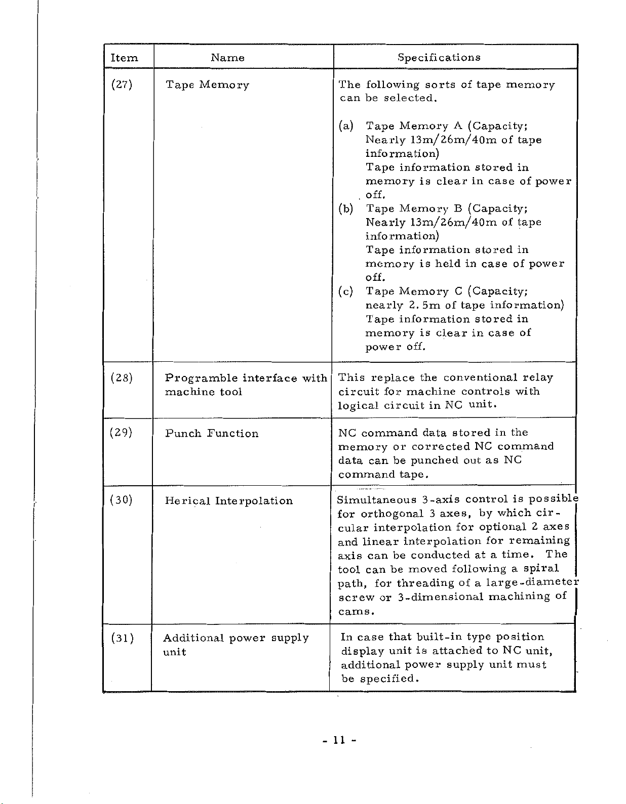
(27)
(28)
Tape
Prog
machine
ramble
Memory
tool
interface
with
The
following
can
be
(a)
Tape
Nearly
information)
Tape
memory
off.
.
(b)
Tape
Nearly
information)
Tape
memory
off.
(c)
Tape
nearly
Tape
memory
power
This
circuit
logical
selected.
replace
for
circuit
sorts
Memory
tape
of
A
(Capacity
13m/26m/40m
information
is
clear
Memory
stored
in
B
(Capacity;
case
13m/26m/40m
in
(Capacity;
C
tape
of
controls
unit.
NC
stored
case
stored
in
case
information
held
is
Memory
5m
2.
information
is
clear
off.
conventional
the
machine
in
memory-
;
tape
of
in
of
power
of
tape
in
power
of
information)
in
of
relay
with
(29)
(30)
(31)
Punch
Herical
Additional
unit
Function
Interpolation
power
supply
NC
command
memory
data
Simultaneous
for
cular
and
axis
tool
path,
can
command
orthogonal
interpolation
linear
can
can
for
screw
or
cams.
case
In
display
additional
be
that
unit
specified.
data
or
corrected
punched
be
tape.
-axis
3
3
interpolation
conducted
be
moved
be
threading
-dimensional
3
built-in
is
power
stored
axes,
for
following
of
attached
supply
NC
out
control
by
optional
at
a
type
the
in
command
NC
as
is
which
remaining
for
time.
a
a
position
NC
unit
-diameter
must
large
machining
to
possible
cir¬
2
axes
The
spiral
unit,
of
11
-
Item
Name
Specifications
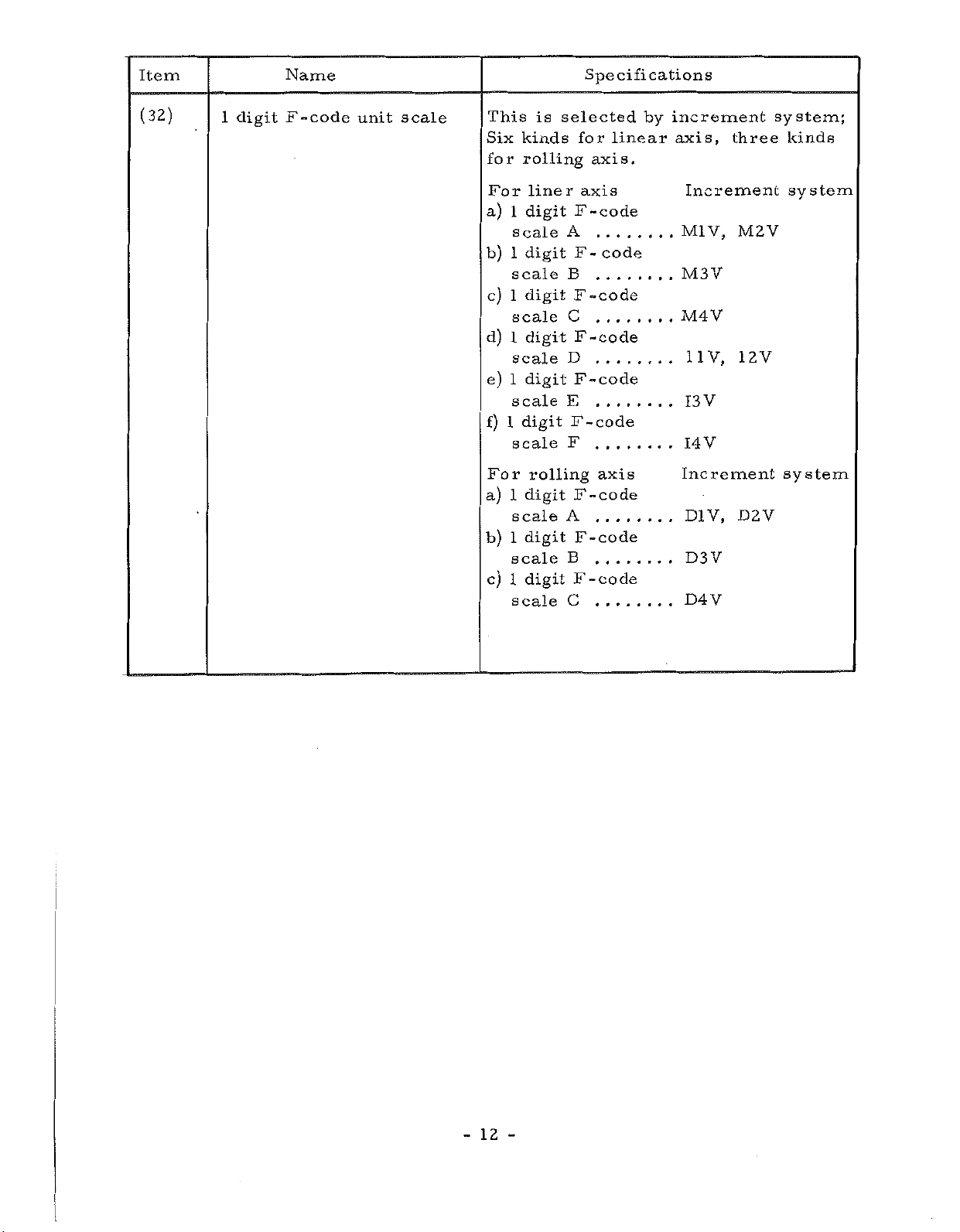
(32)
1
digit
F-code
unit
scale
This
Six
for
For
a)
b)
c)
d)
e)
f)
For
a)
b)
c)
1
1
1
1
1
1
1
1
is
kinds
rolling
lineraxis
digit
scale
digit
scale
1
digit
scale
digit
scale
digit
scale
digit
scale
rolling
digit
scale
digit
scale
digit
scale
selected
for
axis.
F
-code
A
.....
F
code
-
B
F
-code
C
.....
F-code
D
F
-code
E
F
-code
F
axis
F
-code
A
F-code
B
F
-code
C
linear
by
increment
axis,
Increment
V,
Ml
M3Y
M4V
11V,
V
13
V
14
Increment
D1V,
D3V
D4V
three
M2V
12V
D2V
system;
kinds
system
system
12
-
-
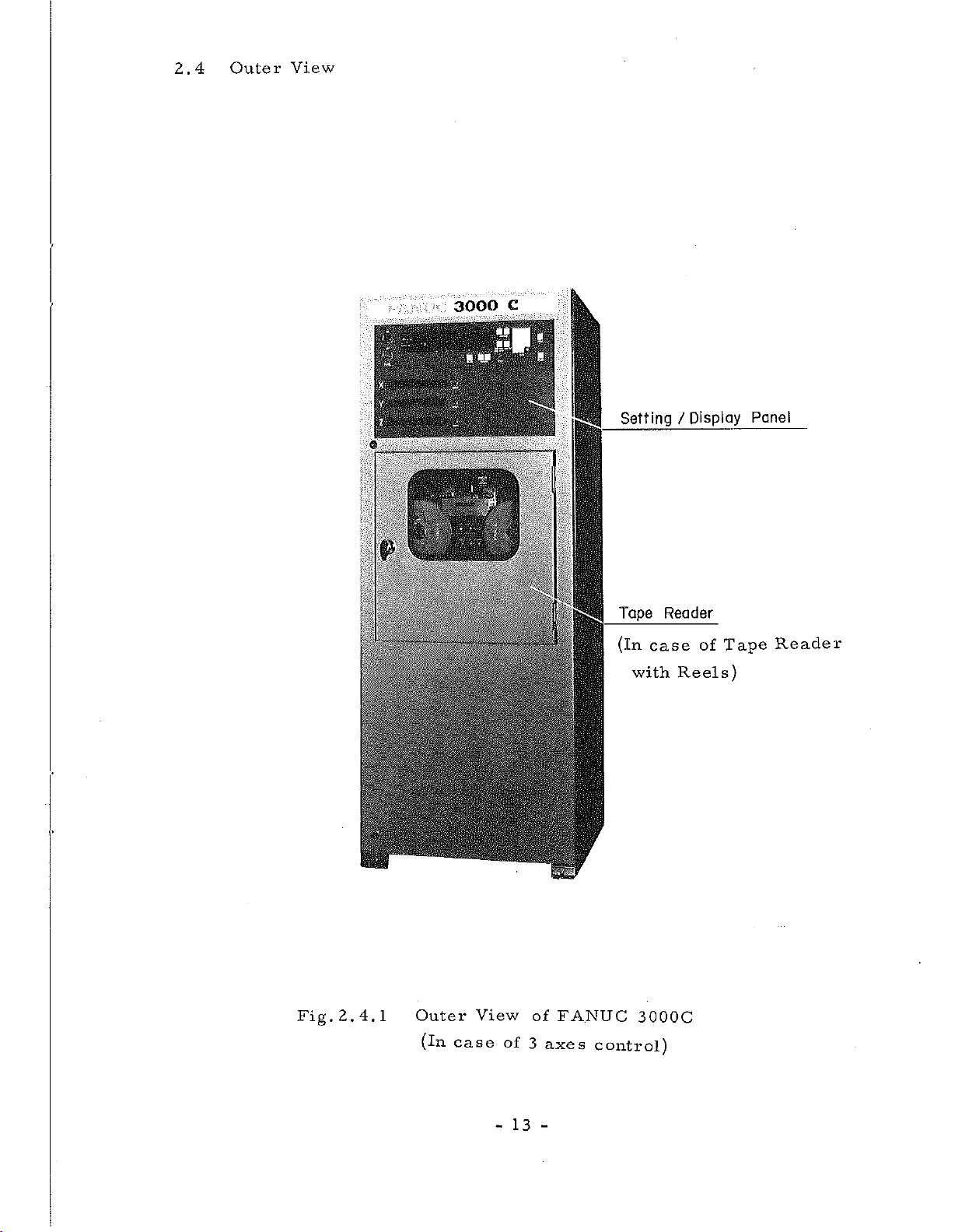
2.4
Outer
View
'4
x
p
1
•
—
:
P
.
I
3000
iv
J.
C
::p-
"
-
s
1
.
::
I
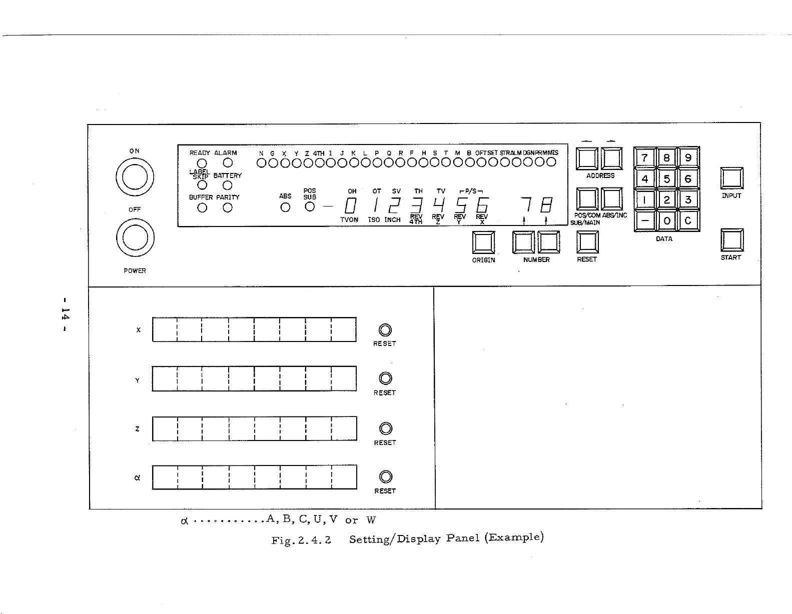
Setting
Tape
(in
case
with
Display
/
Reader
of
Reels)
Tape
Panel
Reader
Fig.
2.4.1
m
Outer
(in
case
View
-
of
13
of
3
-
FANUC
axes
3000C
control)
ON
OFF
READY
o
LABEL
SKIP
o
BUFFER
o
ALARM
o
BATTERY
o
PARITY
o
NG
XYZ
4TH
LP
QRF
HSTMB
OFTSET
JK
I
STRALM
DGNPRMMIS
oooooooooooooooooooooooooo
POS
OH
OT
SV
oo-OIPBHEE
ISO
TVON
INCH
TH
REV
4TH
TV
REV
Z
i-P/S-.
REV
Y
REV
X
IB
_
J
t
ADDRESS
PO
A8S/1NC
S/COM
SUB/MAIN
8
5
2
0
DATA
9
6
INPUT
E
c
7
4
I
NUMBER
Panel
ORIGIN
(Example)
POWER
I
4ÿ
!
X
Y
Z
a
T
T
I
1
T
1
1
T
I
l
1
I
i
1
(X
T T
i
I
i
I
T
1
1
I
f
I
i
1
T
T
i
f
f
I
I
T
T
I
J
i
i
I
1
T
1
I
I
1
I
T
II
I
T
T
r
r
l
f
I
1
T
I
i
I
I
1
A,
B,
2.4.
Fig,
T
1
I
T
I
f
I
i
T
\
F
1
C,U,V
T
RESET
I
i
I
I
T
i
1
T
I
i
2
RESET
RESET
RESET
W
or
Setting/Display
O
o
RESET
START
3.
PROGRAMMING
3.1
3.2
General
Refer
(l)
Table
(2)
Table
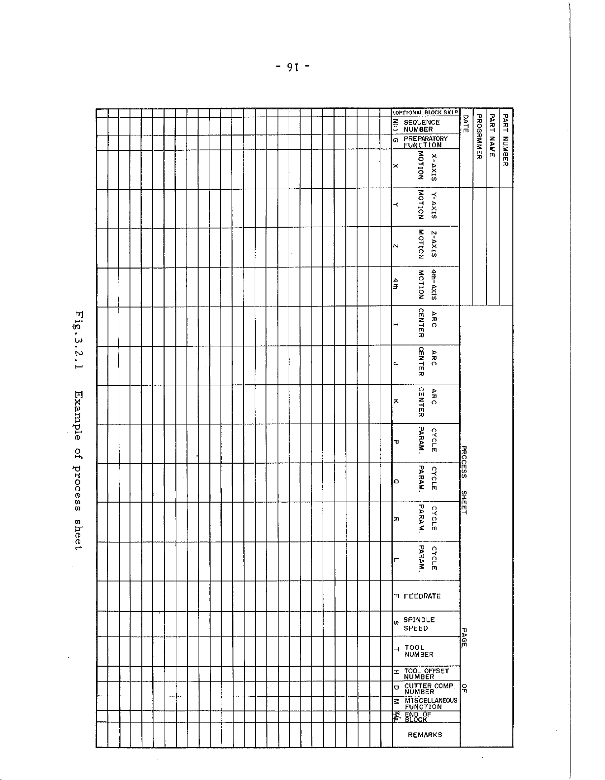
Process
The
of
the
shown
is
Sheet
format
NC
the
to
tape
of
Characters
of
equipment
in
Fig.
appendices
codes
of
the
and
3.2.1.
process
machine
this
of
(appendix
(appendix
sheet
tool.
manual
1)
l)
depends
The
for
on
most
the
following.
the
specifications
generic
example
15
-
OQ
4
M-
u>
TO
w
B
CD
0
H-,
o
o
CD
03
03
03
CD
CD
c+
"
91
-
BLOCK
OPTIONAL
\
SEQUENCE
£
NUMBER
-
Q
PREPARATORY
FUNCTION
X
-<
N
M
c_
T3
o
23
r
SKIP
5
x
o
i
H
HH
X
o
S
X
O
'
H
>
X
o
CO
z
S
N
i
o
>
H
X
n
o
(0
z
s
$
p-
O
I
H
J>
hH
2
2
z
to
o
)>
m
2>
z
O
H
m
XJ
o
m
>
X)
z
O
H
m
X3
O
>
m
23
Z
o
H
m
23
V
o
X)
o
>
r
5
m
T>
O
>
X
X3
O
>
r
5
m
~o
O
>
X
X)
o
r
S
m
T3
o
X>
X
23
O
>
r
2
m
X)
X)
o
m
(O
CO
<o
x
rn
m
H
"0
o
S
t*
X3
->
2)
xt
o
H
G)
m
X>
5
n
X)
t
H
—
z
z
c
s
£
CD
m
m
X>
TI
FEEDRATE
SPINDLE
w
SPEED
TOOL
H
NUMBER
TOOL
X
o
S
ft
OFFSET
NUMBER
CUTTER
COMP.
NUMBER
MISCELLANEOUS
FUNCTION
OF
END
BLOCK
REMARKS
U
CD
PI
O
-n
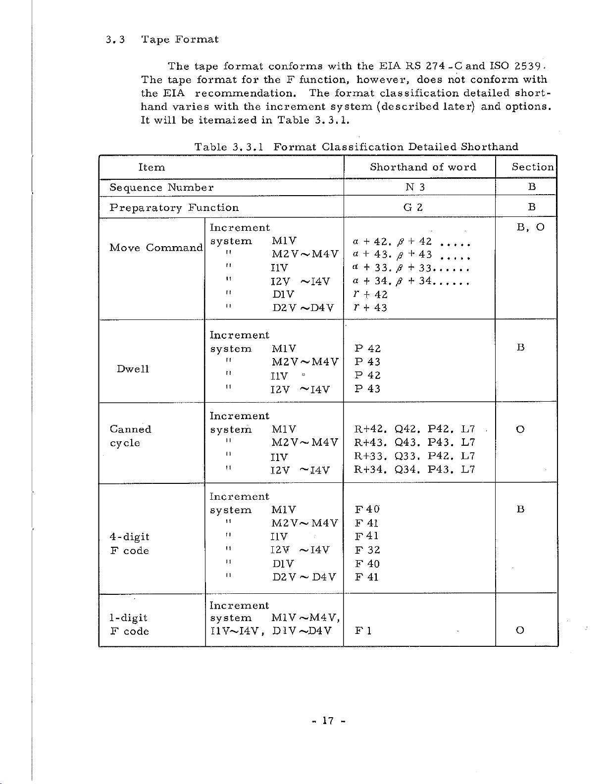
3.
Tape
3
Format
The
the
hand
It
Item
Sequence
Preparatory
Move
Command
Dwell
EIA
will
tape
The
format
tape
recommendation.
varies
itemaized
be
Table
Number
Function
format
for
with
the
3.3.1
Increment
system
"
Increment
system
t
r
(
r
1
1
conforms
the
F
increment
Table
in
Format
M1V
M2V~M4V
I1V
12V
D1V
D2V
M1V
M2V~M4V
I
IV
I2V
with
function,
The
3. 3.
Classification
~I4V
~D4V
~I4V
format
system
1.
a
a
«
cc
r
EIA
the
however,
classification
(described
Shorthand
+
42.
+
43.
+
33.
34,
+
42
+
r
43
+
P
42
P
43
P
42
P
43
RS
Detailed
N
G
p
+
+
p
p
+
p
+
274
does
3
2
42
43
33
34
of
-C
not
later)
Shorthand
word
ISO
and
conform
detailed
and
2539-
with
short¬
options.
Section
B
B
B,
B
O
Canned
cycle
4-digit
F
code
1-digit
code
F
Increment
system
I
I
1
I
!
1
Increment
system
"
Increment
system
I4V,
I1V—
M1V
M2V-M4V
IV
I
~I4V
I2V
M1V
M2V~M4V
I1V
I2V
~I4V
D1V
D2V
M1V
D1V-D4V
D4V
~
~M4
V,
R+42.
R+43.
R+3
R+34.
40
F
F
41
41
F
32
F
F
40
F
41
F
1
Q42.
Q43.
Q3
3
.
Q34.
P42.
P43
.
3
.
P42.
P43.
E7
L7
L7
L7
.
O
B
O
17
-

Item
Shorthand
of
word
Section
Tool
Offset/Cutter
S
Function
T
Function
M
Function
B
Function
Note:
a
(1)
(2)
(3)
(4)
and
T
stands
Leading
Number
Both
Cutter
(0~63)
Compensation.
Compensation
p
stand
for
any
zeros
(N3)
.
D
and
H
Compensation
set
codes
can
for
of
can
be
commanded
any
A,
always
can
number.
of
B
be
and
be
HZ
or
S2
or
or
T2
M2
B3
X,
Y,
C.
omitted
specified
Maximum
for
D2
S4
T5
Z,
Tool
U,
except
on
V,
the
32
offset
W,
for
Tool
(0
I,
Sequence
Offset
~3l)
and
and
J
or
Cutter
B,
O
O
B
O
O
K
/
64
3.4
How
(5)
Among
B
With
(6)
can
the
{V
With
and
to
see
Example:
Increment
function,
the
be
expanded
B
function
the
program
detailed
a
System
S
function
optional
options
a
a
4-
is
5
means
point.
2
means
only
is
copy
shorthand.
52
+
any
is
a
sign.
4
of
function
one
B
function
to
up
not
effective.
of
circule
added,
the
of
a
maximum
two
digits
digits
five
addresses
and
added,
digits.
cutting,
above
of
below
T
selectable.
is
tape
five
function
the
In
helical
X,
digits
the
S
and
this
format
Y,
decimal
5
of
T
functions
case,
interpolation
changes.
Z
and
above
point.
digits
however,
etc.
the
decimal
and
The
increment
system
is
determined
18
-
by
the
following
elements:

(1)
Least
input
increment
(2)
This
on
or
pulse
and
deg.
Least
This
is
NC
is
transmitted
is
mm/p,
of
Any
MDI
Increment
system
setting.
builder
M1V
M2V
the
least
tape
or
command
movement
the
the
least
inch/p
the
increment
the
for
unit
on
the
increment
unit
or
Refer
actual
Table
Least
inc
0.01
0.001
of
MDI
amount
from
in
deg./p.
systems
to
increment
3.4.1
rement
movement
unit.
NC
the
which
the
description
input
mm
mm
amount
This
machine
of
equipment
it
moves.
shown
system.
Increment
is
expressed
tool
to
This
in
Table
issued
Systems
Least
increment
0.001
0.001
that
can
for
the
is
3.4.1
by
command
mm/
mm/
be
specified
in
mm,
one
command
machine
expressed
is
the
machine
p
p
inch
tool,
selected
in
by
tool
M3V
M4V
I1V
I2V
I3V
I4V
D1V
D2V
D3V
D4V
When
the
increment
Increment
Therefore
speed
of
X-axis.
cutter
or
compensation
feed
number
the
0.001
0.001
0.001
0.
0
0.
0.01
0.001
0.
0.001
system
system
rate,
0001
0001
.
0001
001
of
offset
of
mm
mm
inch
inch
inch
inch
deg.
deg.
deg.
deg.
of
X,
X-axis
pulses
or
circular
Y
and
amount,
according
is
0.0005
0.0002
0.0001
0.0001
0.00005
0.00002
0.001
0.001
0.0005
0.0002
interpolation
Z-axis
regarded
are
etc
to
mm/
mm/
inch/p
inch/p
inch/p
inch/p
deg/p
deg/p
deg/p
deg/p
must
as
a
changed
the
increment
p
p
selected,
is
same.
be
fundamental.
into
pulse
system
for
Be
other
careful
than
the
of
X-axis.
designation
19
-
-
of
feed
rate
and
offset
amount
3.5
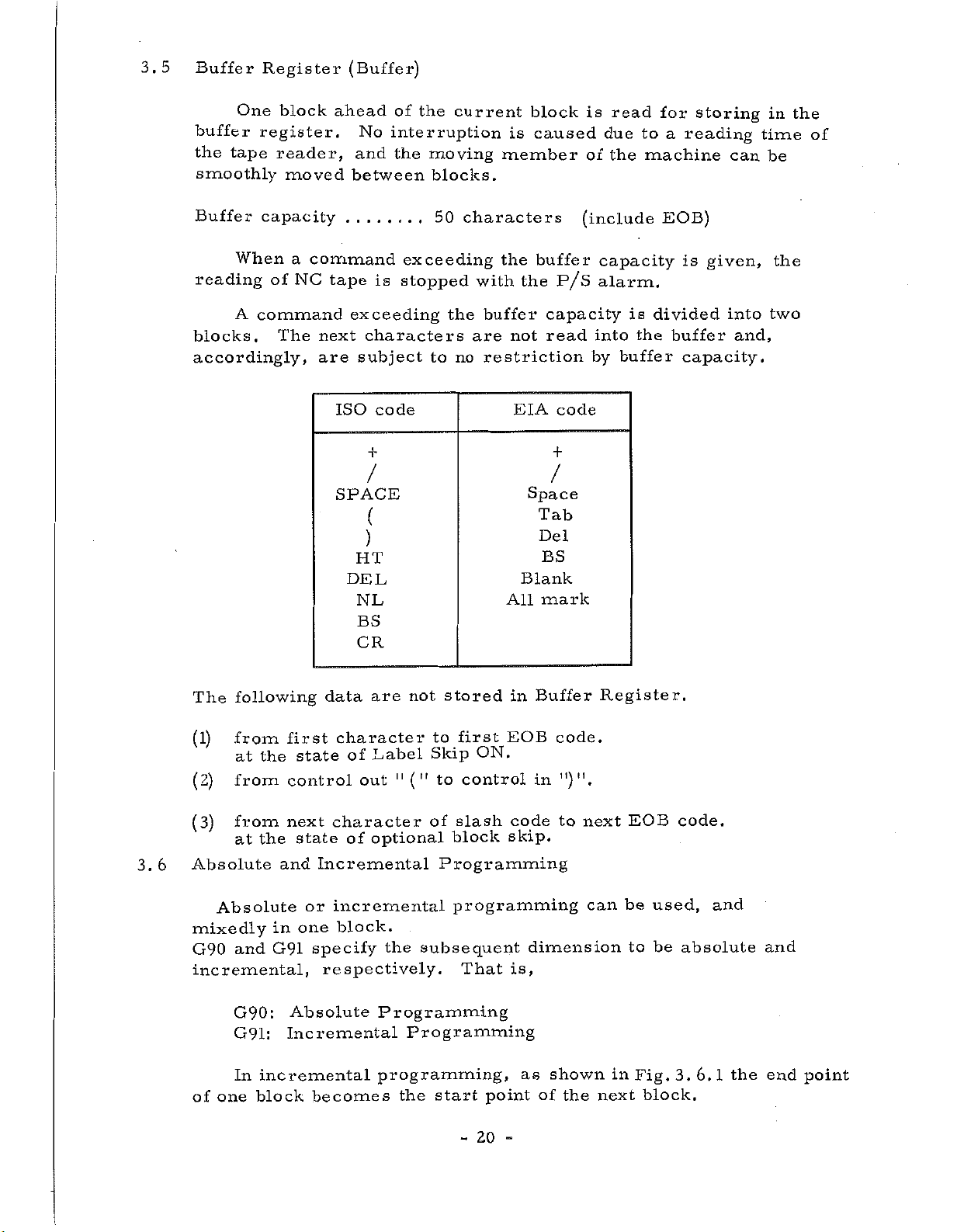
Buffer
One
buffer
the
tape
smoothly
Register
block
register.
reader,
moved
(Buffer)
ahead
No
and
between
of
the
current
interruption
the
moving
blocks.
block
is
caused
member
is
of
read
due
the
for
to
a
machine
storing
reading
can
in
time
be
the
of
Buffer
capacity
When
reading
A
command
blocks.
accordingly,
of
The
command
a
NC
next
are
tape
exceeding
characters
subject
ISO
/
SPACE
(
)
HT
DEL
NL
BS
CR
exceeding
is
stopped
code
to
50
the
no
characters
the
with
buffer
not
are
restriction
EIA
All
buffer
the
capacity
read
+
/
Space
Tab
Del
BS
Blank
mark
(include
P/S
code
capacity
alarm.
into
buffer
by
is
the
EOB)
is
divided
buffer
capacity.
given,
into
and,
the
two
3.6
following
The
from
(1)
at
from
(2)
from
(3)
the
at
Absolute
Absolute
mixedly
and
G90
incremental,
G90:
G91:
incremental
In
one
of
block
first
state
the
control
next
state
and
or
one
in
G91
Absolute
Incremental
are
data
character
Label
of
out
character
optional
of
Incremental
incremental
block.
specify
respectively.
becomes
stored
not
first
to
Skip
11
to
("
the
control
of
slash
block
Programming
programming
subsequent
That
Programming
Programming
programming,
the
start
-
ON.
point
20
Buffer
in
EOB
in
code
skip.
dimension
is,
as
of
code.
")".
to
shown
the
Register.
next
can
in
next
EOB
be
to
Fig.
used,
be
3.
block.
code.
and
absolute
6.1
the
and
end
point

V3
Y
axis
which
the
In
zero
Fig.
Absolute
tool
a
point.
Y
Y2
VI
3.
is
3
Y]~~
KU1
6.1
programming,
to
Y
4-
Incremental
move,
axis
-xi
X2
—
i
i
J-U3-J
U2
coordinate
as
is
always
t
d
-
—
X3
shown
I
i
I
given
in
in
X
axis
values
Fig.
coordinate
a
X
axis
3.
6.
2
the
point
value
to
from
3.7
Increment
system
Maximum
M1V
M2V
M3V
M4V
I1V
12
V
programmable
the
Maximum
value
+
±
+
+
+
+
is
It
always
over
If
possibility
Fig.
Programmable
8388.
3.
6.
60
8388.607
4194.
303
1677.721
838.860
838.8607
forbidden
dimensions.
maximum
of
changing
2
Absolute
command
mm
mm
mm
mm
inch
inch
command
coordinate
Dimensions
to
give
value
the
sign.
Increment
system
I3V
14
V
D1V
D2V
D3V
D4V
the
command
is
values
over
commanded,
Maximum
value
+
419.4303
167.7721
±
8
388
+
8388.607
+
+
4194.303
1677.721
±
maximum
.
there
60
is
command
inch
inch
deg
deg
deg
deg
21
-
3.
8
In
maximum
In
command
Tape
Code
case
case
circular
of
command
of
inch/metric
value
is
also
value.
arc,
the
conversion
restricted.
radius
(See
is
is
4.1.4
necessary
selected,
under
maximum
(9))
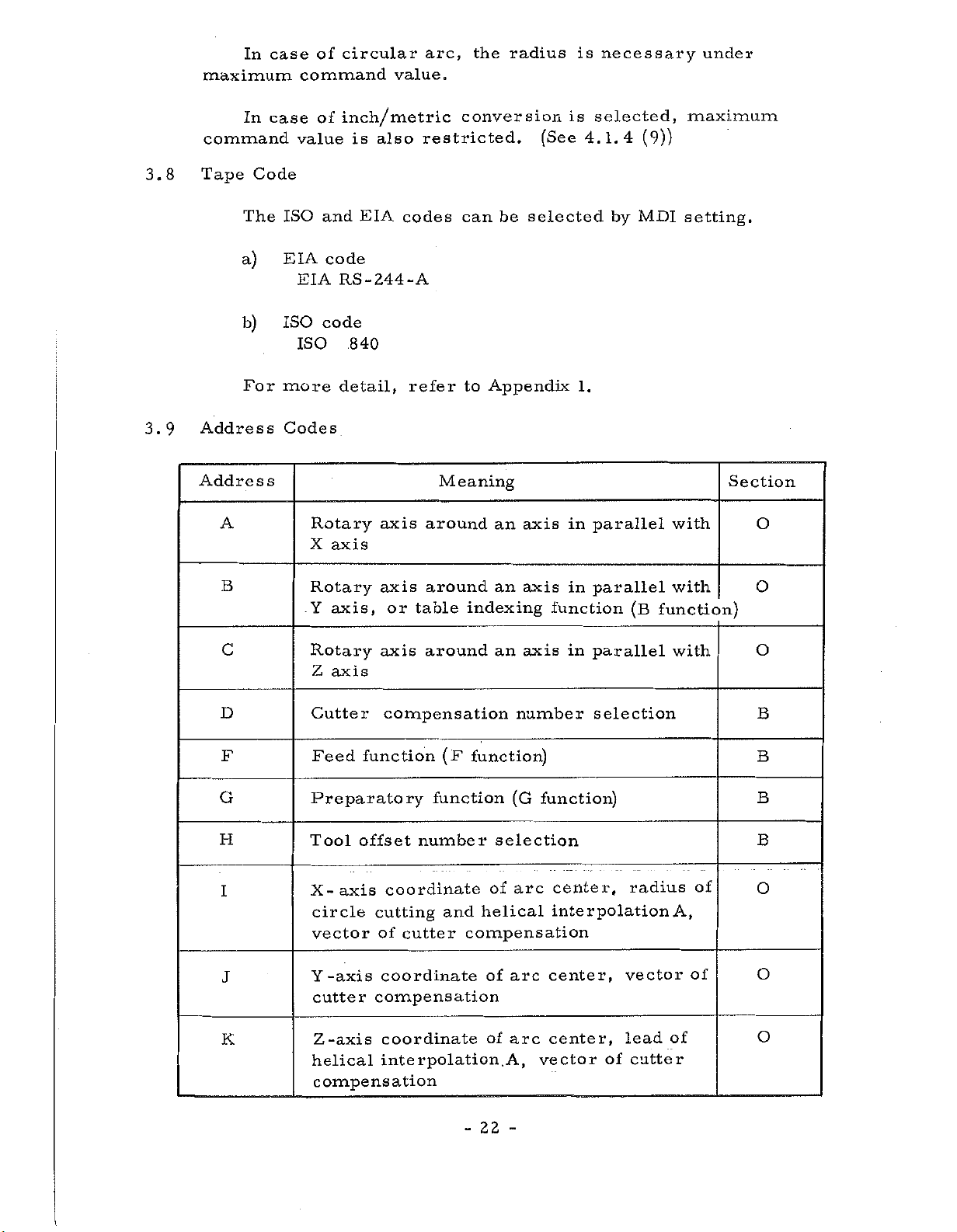
3.9
The
a)
b)
For
Address
Address
A
B
c
ISO
EIA
EIA
ISO
ISO
more
Codes
Rotary
X
Rotary
Y
Rotary
Z
EIA
and
code
RS-244-A
code
.840
detail,
axis
axis,
axis
axis
axis
or
axis
codes
refer
around
around
table
around
can
to
Appendix
Meaning
indexing
be
an
an
an
selected
axis
axis
function
axis
1.
in
in
in
by
parallel
parallel
parallel
MDI
(B
function)
setting.
with
with
with
Section
O
O
O
G
H
D
I
F
J
K
Cutter
Feed
compensation
function
Preparatory
Tool
X-axis
circle
Y
helical
offset
coordinate
cutting
vector
-axis
cutter
Z-axis
compensation
of
coordinate
compensation
coordinate
interpolation.
function
number
cutter
(F
function)
selection
of
helical
and
compensation
of
of
22
-
number
(G
arc
arc
arc
A,
-
selection
function)
center,
interpolation
center,
center,
vector
of
radius
vector
lead
cutter
of
A,
of
of
B
B
B
B
O
O
O
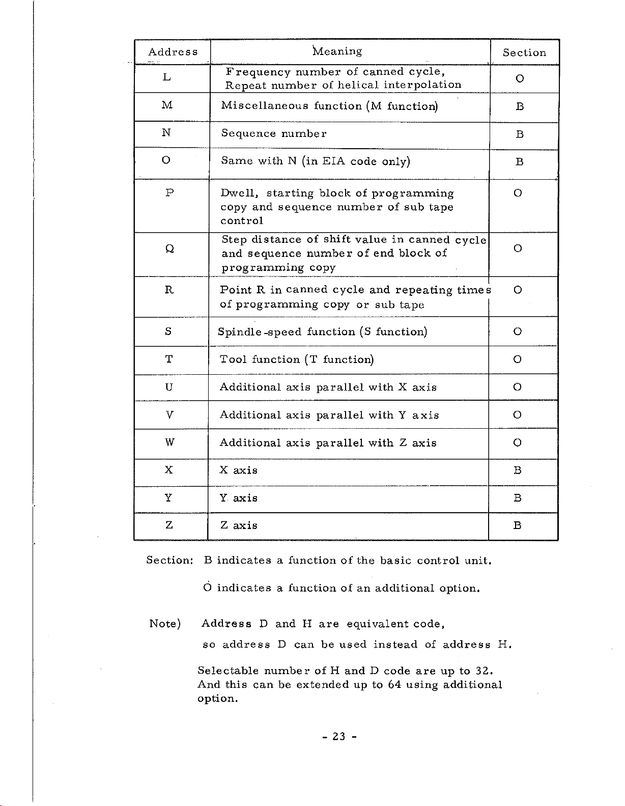
Address
Wteaning
Section
L
M
N
O
canned
of
of
helical
EIA
code
block
shift
of
number
value
cycle
copy
function)
(M
programming
of
end
and
or
sub
(S
function)
number
number
N
starting
sequence
canned
in
number
function
(in
of
number
copy
function
(T
Frequency
Repeat
Miscellaneous
Sequence
Same
P
Dwell,
copy
control
Q
Step
and
with
and
distance
sequence
programming
R
S
T
Point
of
Spindle
Tool
R
programming
-speed
function
cycle,
interpolation
function)
only)
sub
canned
block
tape
tape
of
in
repeating
of
cycle
times
O
B
B
B
O
O
O
O
0
U
V
W
X X
Y
Z Z
Section:
Note)
Additional
Additional
Additional
axis
Y
axis
axis
B
indicates
6
indicates
Address
so
address
Selectable
And
this
option.
D
number
can
axis
axis
axis
a
function
function
a
and
D
be
parallel
parallel
parallel
H
are
can
be
of
extended
of
of
equivalent
used
H
and
with
with
with
the
an
D
up
X
Y
Z
basic
additional
instead
code
to
64
using
axis
axis
axis
control
code,
of
are
unit.
option.
address
to
up
additional
O
O
O
B
B
B
H.
32.
23
-
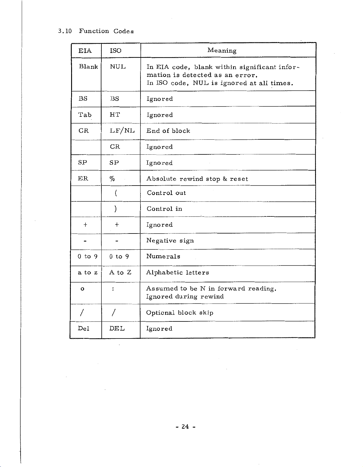
3.10
Function
Codes
EIA
Blank
BS
Tab
CR
SP
ER
ISO
NUL
BS
HT
LF/NL
CR
SP
%
(
)
EIA
In
mation
ISO
In
Ignored
Ignored
of
End
Ignored
Ignored
Absolute
Control
Control
code,
is
code,
block
out
in
blank
detected
NUL
rewind
Meaning
within
as
is
ignored
stop
fk
an
reset
significant
error.
at
all
infor¬
times.
0
a
o
/
Del
to
to
++
to
0
9
z
9
A
to
Z
/
DEL
Ignored
Negative
Numerals
Alphabetic
Assumed
Ignored
Optional
Ignored
sign
letters
to
during
block
be
in
N
rewind
skip
forward
reading.
24
-
(1)
Label
Skip
Function
(2)
(3)
a
tape
If
mation
information
The
EOB
mation.
The
display
a)
b)
Control
All
parenthesis
formed.
reset,
Stop
has
Absolute
The
this
reset.
reader
code
label
the
the
information
and
no
code
code
is
read
is
ignored
has
And
skip
panel
power
equipment
Out/in
code
When
Control
Reset
effects
Rewind
means
read
is
this
If
with
reels,
in
until
been
this
at
function
lights
is
(Only
including
is
the
In
is
this
in
Stop
an
within
code
with
until
read,
up
turned
is
ignored,
power
is
effected.
not
absolute
is
the
the
the
reset
a
state
becomes
when
on,
reset
at
EOB
used
section.
and
Significant
read
tape
Label
End
is
Label
in
ISO
is
in
Reset
during
feed
of
command
called
on
or
a
mode
code)
between
and
turned
However
this
rewind
is
Skip
Block
the
lamp
skip
and
other
TH
and
on,
section.
stop,
Information,
manual
stopped
Function
code
is
Tape
the
left
or
(EOB)
read
Significant
turns
lamp
than
parenthesis
TV
checks
when
Absolute
And
in
and
operation
unconditionally.
on,
after
off.
on
MDI
the
Rewind
EOB
addition,
means
it
all
infor¬
is
read.
first
the
Infor¬
the
mode.
and
are
not
equipment
code
when
a
the
tape
on
right
per¬
is
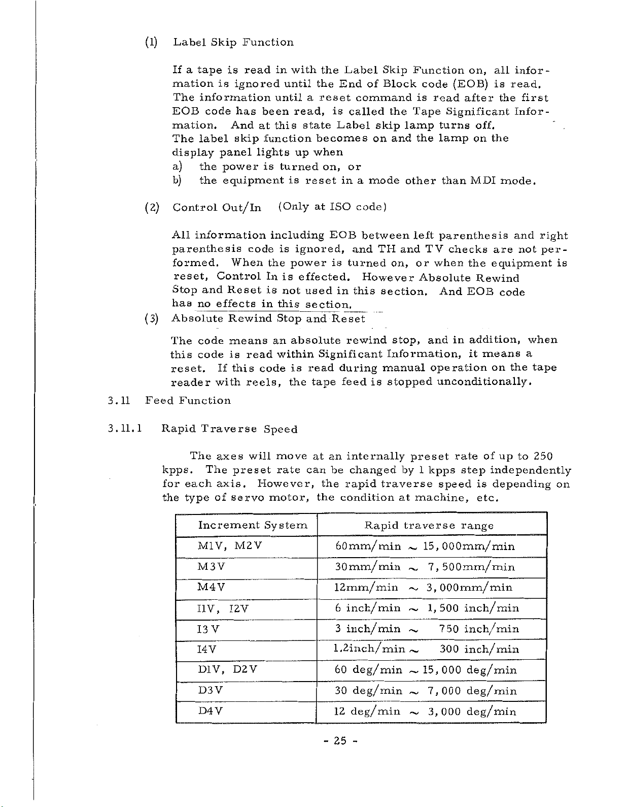
3.11
3.11.1
Feed
Function
Rapid
kpps.
for
the
Traverse
The
The
each
type
Increment
M1V,
M3
M4V
I1V,
V
13
I4V
D1V,
D3V
D4V
axes
axis.
of
V
preset
servo
M2
I2V
D2V
Speed
will
However,
motor,
System
V
move
rate
an
the
the
internally
be
rapid
condition
at
can
60mm/
30mm/
12mm/min
6
inch/min
3
inch/min
1.2inch/minÿ,
60
30
12
changed
traverse
Rapid
min
min
deg/min
deg/min
deg/min
preset
by
1
at
machine,
traverse
15,
~~
~
~
~~
15,
~
~
~
up
of
independently
is
depending
etc.
kpps
speed
rate
step
range
OOOmm/min
7,
500mm/
3,
OOOmm/min
1,500
750
300
000
7,000
3,000
min
inch/min
inch/min
inch/min
deg/min
deg/min
deg/min
to
250
on
-
25
-
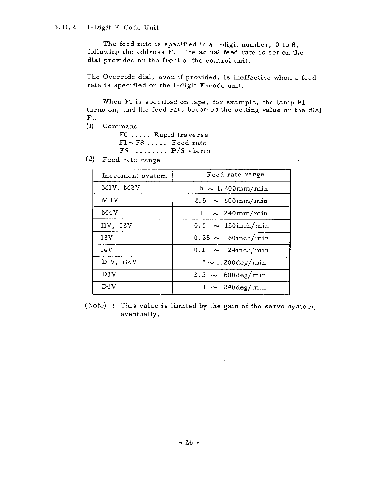
3.11.2
1-Digit
The
following
provided
dial
F-Code
feed
the
Unit
rate
address
on
the
is
specified
front
F.
The
of
the
in
a
actual
control
-digit
1
feed
number,
rate
unit.
to
8,
0
is
set
on
the
The
rate
turns
FI.
(l)
(2)
Override
is
specified
When
on,
and
Command
FO
F1~F8
F9
Feed
Increment
M1V,
M3V
M4Y
I1V,
I3V
I4V
D1Y,
D3V
D4V
I2V
D2V
FI
rate
M2V
dial,
is
the
even
on
specified
feed
Rapid
.....
the
if
1
-digit
rate
traverse
Feed
on
P/S
range
system
provided,
F-code
tape,
becomes
rate
alarm
5
2.5
1
0.5
0.25
0.1
5
2.5
1
is
ineffective
unit.
for
example,
the
setting
Feed
~
~
rate
1,
200mm/min
~
600mm/
240mm/
~
120inch/min
~
~
60inch/min
~
24inch/min
l,200deg/min
600deg/min
~
240deg/min
~
range
min
min
the
value
when
lamp
on
a
FI
the
feed
dial
(Note)
This
:
eventually.
value
is
limited
-
26
-
by
the
gain
of
the
servo
system,
 Loading...