


 Loading...
Open CNC
Basic Operation Package 1
Operator's Manual
B-62994EN/02

•No part of this manual may be reproduced in any form.
•All specifications and designs are subject to change without notice.
The products in this manual are controlled based on Japan’s “Foreign Exchange and Foreign Trade Law”. The export from Japan may be subject to an export license by the government of Japan.
Further, re-export to another country may be subject to the license of the government of the country from where the product is re-exported. Furthermore, the product may also be controlled by re-export regulations of the United States government.
Should you wish to export or re-export these products, please contact FANUC for advice.
In this manual we have tried as much as possible to describe all the various matters. However, we cannot describe all the matters which must not be done, or which cannot be done, because there are so many possibilities.
Therefore, matters which are not especially described as possible in this manual should be regarded as ”impossible”.
This manual contains the program names or device names of other companies, some of which are registered trademarks of respective owners. However, these names are not followed by ® or ™ in the main body.

Warnings and notices for this publication
GFLE-003
Warning
In this manual we have tried as much as possible to describe all the various matters. However, we cannot describe all the matters which must not be done, or which cannot be done, because there are so many possibilities.
Therefore, matters which are not especially described as possible in this manual should be regarded as “impossible”.
Notice
This document is based on information available at the time of its publication. While efforts have been made to be accurate, the information contained herein does not purport to cover all details or variations in hardware or software, nor to provide every contingency in connection with installation, operation, or maintenance. Features may be described herein which are not present in all hardware and software systems. FANUC CNC assumes no obligation of notice to
holders of this document with respect to changes subsequently made.
FANUC CNC makes no representation or warranty, expressed, implied, or statutory with
respect to, and assumes no responsibility for accuracy, completeness, sufficiency, or usefulness of the information contained herein. No warranties of merchantability or fitness for purpose shall apply.
The following are Registered Trademarks of FANUC CNC
CIMPLICITY® |
Genius® |
The following are Trademarks of FANUC CNC
Alarm Master |
PROMACRO |
CIMSTAR |
Series Five |
Field Control |
Series 90 |
Genet |
Series One |
Helpmate |
Series Six |
LogicMaster |
Series Three |
Modelmaster |
VuMaster |
PowerMotion |
Workmaster |
ProLoop |
|
© Copyright 1998 FANUC Ltd. Authorized Reproduction FANUC CNC Europe S.A.
All Rights Reserved
No part of this manual may be reproduced in any form.
All specifications and designs are subject to change without notice.

SAFETY PRECAUTIONS
This manual includes safety precautions for protecting the user and preventing damage to the machine. Precautions are classified into Warnings and Cautions according to their bearing on safety. Also, supplementary information is described as Notes. Read the Warnings, Cautions, and Notes thoroughly before attempting to use the machine.
WARNING
Applied when there is a danger of the user being injured or when there is a danger of both the user being injured and the equipment being damaged if the approved procedure is not observed.
CAUTION
Applied when there is a danger of the equipment being damaged, if the approved procedure is not observed.
NOTE
Notes is used to indicate supplementary information other than
Warnings and Cautions.
¡ Read this manual carefully, and store it in a safe place.
s-1

SAFETY PRECAUTIONS |
B-62994EN/02 |
General Warnings and Cautions
WARNING
1.Never attempt to machine a workpiece without first checking the operation of the machine. Before starting a production run, ensure that the machine is operating correctly by performing a trial run using, for example, the single block, feedrate override, or machine lock function, or by operating the machine with neither a tool nor workpiece mounted. Failure to confirm the correct operation of the machine may result in the machine behaving unexpectedly, possibly causing damage to the workpiece and/or machine itself, or injury to the user.
2.Before operating the machine, thoroughly check the entered data. Operating the machine with incorrectly specified data may result in the machine behaving unexpectedly, possibly causing damage to the workpiece and/or machine itself, or injury to the user.
3.Ensure that the specified feedrate is appropriate for the intended operation. Generally, for each machine, there is a maximum allowable feedrate. The appropriate feedrate varies with the intended operation. Refer to the manual provided with the machine to determine the maximum allowable feedrate. If a machine is run at other than the correct speed, it may behave unexpectedly, possibly causing damage to the workpiece and/or machine itself, or injury to the user.
4.When using a tool compensation function, thoroughly check the direction and amount of compensation.
Operating the machine with incorrectly specified data may result in the machine behaving unexpectedly, possibly causing damage to the workpiece and/or machine itself, or injury to the user.
5.The parameters for the CNC and PMC are factory-set. Usually, there is no need to change them. When, however, there is no alternative other than to change a parameter, ensure that you fully understand the function of the parameter before making any change.
Failure to set a parameter correctly may result in the machine behaving unexpectedly, possibly causing damage to the workpiece and/or machine itself, or injury to the user.
s-2

B-62994EN/02 |
SAFETY PRECAUTIONS |
CAUTION
1.The operator's manual for Basic Operation Package 1 describes all the basic functions of the CNC unit, including the optional functions. The selected optional functions vary with the machine. Some functions described in the manual may not, therefore, be supported by your machine. Check the machine specifications before using Basic Operation Package 1.
2.Some machine operations and screen functions are implemented by the machine tool builder. For an explanation of their usage and related notes, refer to the manual provided by the machine tool builder.
For example:
•On some machines, executing a tool function causes the tool change unit to operate. When executing a tool function on such a machine, stand well clear of the tool change unit. Otherwise, there is a danger of injury to the operator.
•Many auxiliary functions trigger physical operations, such as rotation of the spindle. Before attempting to use an auxiliary function, therefore, ensure that you are fully aware of the operation to be triggered by that function.
NOTE
•Command programs, parameters, and variables are stored in nonvolatile memory in the CNC. Generally, the contents of memory are not lost by a power on/off operation. However, the contents of memory may be erased by mistake, or important data in nonvolatile memory may have to be erased upon recovering from a failure.
To enable the restoration of data as soon as possible if such a situation arises, always make a backup of the data in advance.
s-3

SAFETY PRECAUTIONS |
B-62994EN/02 |
Warnings and Cautions Relating to Basic Operation Package 1
Warnings and cautions relating to Basic Operation Package 1 are explained in this manual. Before using the function, read this manual thoroughly to become familiar with the provided Warnings, Cautions, and Notes.
On the next page, the points to be noted when Basic Operation Package 1 is used are summarized. These points are not explained in Chapter 1 and the subsequent chapters of this manual. Read this part before attempting to use the function.
s-4

B-62994EN/02 |
SAFETY PRECAUTIONS |
Important Notice
The following summarizes the points to be noted when Basic Operation Package 1 is used. Before attempting to use Basic Operation Package 1, read the following:
CAUTION
•This manual does not explain in detail those operations and parameters that vary from one CNC model to another and which vary with options. For an explanation of such operations and parameters, refer to the relevant CNC manual and the manual supplied by the machine tool builder.
•This manual describes as many reasonable variations in usage as possible. It cannot address every combination of features, options, and commands that should not be attempted. If a particular combination of operations is not described, it should not be attempted.
s-5

B-62994EN/02 |
CONTENTS |
SAFETY PRECAUTIONS ......................................................................................................................... |
s-1 |
General Warnings and Cautions
Warnings and Cautions Relating to Basic Operation Package 1
Important Notice
PREFACE............................................................................................................................................................... |
p-1 |
Basic Operation Package 1 Features and Restrictions
Contents of the Product Package
Organization of This Manual
Notation Conventions
CONTENTS........................................................................................................................................................... |
|
c-1 |
||
1. |
SETUP................................................................................................................................................................. |
|
1 |
|
|
1.1 |
Operating Environment.......................................................................................................................... |
2 |
|
|
1.2 |
Installing Basic Operation Package 1 .................................................................................................. |
4 |
|
|
1.3 |
Uninstalling Basic Operation Package 1 ............................................................................................. |
7 |
|
2. |
BASIC KNOWLEDGE .......................................................................................................................... |
9 |
||
|
2.1 |
Starting and Terminating Basic Operation Package 1..................................................................... |
10 |
|
|
|
2.1.1 Starting Basic Operation Package 1............................................................................................... |
10 |
|
|
|
2.1.2 Terminating Basic Operation Package 1........................................................................................ |
11 |
|
|
2.2 |
Window Names and Functions ........................................................................................................... |
13 |
|
|
2.3 |
Selecting and Positioning Windows................................................................................................... |
21 |
|
|
|
2.3.1 |
Selecting a window ........................................................................................................................ |
21 |
|
|
2.3.2 |
Positioning a window..................................................................................................................... |
22 |
|
2.4 |
Selecting a Path ..................................................................................................................................... |
24 |
|
|
2.5 |
Displaying Version Information ......................................................................................................... |
25 |
|
3. SETTING THE PARAMETERS REQUIRED |
|
|||
|
TO USE BASIC OPERATION PACKAGE 1...................................................................... |
26 |
||
|
3.1 |
Setting the CNC Parameters................................................................................................................ |
27 |
|
|
3.2 |
Specifying a Node................................................................................................................................. |
29 |
|
4. |
POSITION DISPLAY............................................................................................................................ |
30 |
||
|
4.1 |
Overall Position Display ...................................................................................................................... |
31 |
|
|
4.2 |
Displaying the Relative Position ........................................................................................................ |
33 |
|
|
|
4.2.1 |
Resetting relative coordinates ........................................................................................................ |
35 |
|
|
4.2.2 |
Presetting relative coordinates ....................................................................................................... |
36 |
c-1
CONTENTS |
B-62994EN/02 |
|
4.2.3 Setting the machine position to the floating reference position...................................................... |
38 |
|
4.2.4 Presetting the workpiece coordinate system................................................................................... |
39 |
4.3 |
Displaying the Absolute Position ....................................................................................................... |
42 |
4.4 |
Displaying the Machine Position........................................................................................................ |
44 |
4.5 |
Displaying the Distance to Go ............................................................................................................ |
45 |
4.6 |
Displaying the Amount of Handle Interruption................................................................................ |
46 |
|
4.6.1 Canceling the amount of handle interruption ................................................................................. |
47 |
4.7 |
Displaying the Operating Monitor...................................................................................................... |
49 |
4.8 |
Displaying the Machining Time and Machined Parts Count ......................................................... |
50 |
5. NC PROGRAM.......................................................................................................................................... |
52 |
|
5.1 Editing a NC Program .......................................................................................................................... |
53 |
|
5.1.1 |
Getting a program from the NC ..................................................................................................... |
56 |
5.1.2 |
Writing a NC program back to the NC .......................................................................................... |
58 |
5.1.3 |
Inserting a NC program from a disk............................................................................................... |
59 |
5.1.4 |
Writing a NC program to a disk..................................................................................................... |
60 |
5.1.5 |
Finding a character string in a NC program ................................................................................... |
61 |
5.1.6 |
Replacing a character string in a NC program ............................................................................... |
62 |
5.1.7 |
Selecting character strings in a NC program.................................................................................. |
63 |
5.1.8 |
Cutting character strings from a NC program ................................................................................ |
64 |
5.1.9 |
Copying character strings from a NC program .............................................................................. |
66 |
5.1.10 |
Pasting character strings into a NC program.................................................................................. |
67 |
5.1.11 |
Inserting sequence numbers into a NC program ............................................................................ |
68 |
5.1.12 |
Entering a coordinate value into a NC program............................................................................. |
71 |
5.1.13 |
Displaying the top of a NC program .............................................................................................. |
73 |
5.1.14 |
Displaying the end of a NC program.............................................................................................. |
74 |
5.1.15 |
Stamping the machining time......................................................................................................... |
75 |
5.2 Editing an MDI Program...................................................................................................................... |
77 |
|
5.2.1 |
Finding a character string in an MDI program............................................................................... |
79 |
5.2.2 |
Replacing a character string in an MDI program ........................................................................... |
80 |
5.2.3 |
Selecting character strings in an MDI program.............................................................................. |
81 |
5.2.4 |
Cutting character strings from an MDI program ............................................................................ |
82 |
5.2.5 |
Copying character strings from an MDI program .......................................................................... |
84 |
5.2.6 |
Pasting character strings into an MDI program.............................................................................. |
85 |
5.2.7 |
Inserting sequence numbers into an MDI program ........................................................................ |
86 |
5.2.8 |
Displaying the top of an MDI program .......................................................................................... |
88 |
5.2.9 |
Displaying the end of an MDI program ......................................................................................... |
89 |
5.3 Displaying the NC Program Directory............................................................................................... |
90 |
|
5.3.1 |
Copying a NC program .................................................................................................................. |
92 |
5.3.2 |
Deleting a NC program .................................................................................................................. |
94 |
5.3.3 |
Selecting a NC program to be executed ......................................................................................... |
95 |
5.3.4 |
Changing a NC program comment................................................................................................. |
97 |
5.3.5 |
Changing the NC program directory contents................................................................................ |
98 |
c-2

B-62994EN/02 |
CONTENTS |
5.4 |
Checking the Program Currently Being Executed ......................................................................... |
100 |
|
5.4.1 Rewinding the tape to the beginning of the NC program ............................................................. |
101 |
|
5.4.2 Searching for a sequence number................................................................................................. |
103 |
5.5 |
Displaying the Current and Next Blocks of the NC Program Being Executed ......................... |
105 |
5.6 |
Restarting a NC Program ................................................................................................................... |
106 |
|
5.6.1 Setting the axis order of movement to the program restart position............................................. |
108 |
|
5.6.2 Searching for a sequence/block number....................................................................................... |
109 |
5.7 |
Displaying the Machining Times...................................................................................................... |
112 |
5.8 |
Displaying the B-Axis Operating Status.......................................................................................... |
114 |
6. SETTING |
...................................................................................................................................................... |
116 |
|
6.1 |
Setting ..........................................................................................................................................Data |
117 |
|
6.2 |
Operating .........................................................................Time, Parts Count, and Timer Settings |
121 |
|
6.3 |
Tool Offset ............................................................................................................................Settings |
124 |
|
|
6.3.1 ..........................................................Entering a relative coordinate value as the tool offset data |
127 |
|
|
6.3.2 ........................................................................Entering a measured value as the tool offset data |
129 |
|
|
6.3.3 ..........................................................................................................Clearing all tool offset data |
130 |
|
6.4 |
Custom ......................................................................................................Macro Variable Settings |
132 |
|
|
6.4.1 ............................................................................................................ |
Displaying local variables |
134 |
|
6.4.2 .........................................................................................................Common variable 1 settings |
136 |
|
|
6.4.3 .........................................................................................................Common variable 2 settings |
137 |
|
|
6.4.4 .............................................................Entering a relative coordinate value as a macro variable |
139 |
|
|
6.4.5 ............................................................................................Clearing all custom macro variables |
140 |
|
|
6.4.6 ..............................................................................................Setting a blank in a macro variable |
142 |
|
6.5 |
Workpiece ....................................................................................................Origin Offset Settings |
143 |
|
|
6.5.1 ..........................................................Entering a measured value as workpiece origin offset data |
145 |
|
6.6 |
Tool Life ..............................................................................................Management Data Settings |
147 |
|
|
6.6.1 .....................................Adding a tool to a tool group included in the tool life management data |
151 |
|
|
6.6.2 Changing the life status of a tool included in the tool life management data |
|
|
|
.................................................................................................... |
(for machining center systems) |
154 |
|
6.6.3 Changing the life status of a tool included in the tool life management data |
|
|
|
........................................................................................................................ |
(for lathe systems) |
157 |
|
6.6.4 Setting the life counter data included in the tool life management data |
|
|
|
.................................................................................................... |
(for machining center systems) |
159 |
|
6.6.5 .........Setting the life counter data included in the tool life management data (for lathe systems) |
161 |
|
|
6.6.6 Deleting a tool from a tool group included in the tool life management data |
|
|
|
.................................................................................................... |
(for machining center systems) |
163 |
|
6.6.7 Deleting a tool from a tool group included in the tool life management data |
|
|
|
........................................................................................................................ |
(for lathe systems) |
165 |
6.7 |
Software ..................................................................................................Operator's Panel Settings |
167 |
|
6.8 |
Workpiece .................................................................................Coordinate System Shift Settings |
169 |
|
6.9 |
P-Code ......................................................................................................Macro Variable Settings |
172 |
|
|
6.9.1 ............................................................................................................ |
Displaying local variables |
174 |
|
6.9.2 .........................................................................................................Common variable 1 settings |
175 |
|
c-3

CONTENTS |
B-62994EN/02 |
|
6.9.3 Common variable 2 settings......................................................................................................... |
176 |
|
6.9.4 P-code variable 1 settings ............................................................................................................ |
177 |
|
6.9.5 P-code variable 2 settings ............................................................................................................ |
178 |
|
6.9.6 Setting a blank in a P-code macro variable .................................................................................. |
179 |
6.10 |
Chopping Data Settings ..................................................................................................................... |
180 |
6.11 |
Chuck and Tailstock Barrier Settings .............................................................................................. |
182 |
6.12 |
B-Axis Tool Offset Settings .............................................................................................................. |
186 |
6.13 |
Tool Post Interference Check Settings............................................................................................. |
189 |
6.14 |
2-Path Interference Check Settings .................................................................................................. |
192 |
7. SYSTEM........................................................................................................................................................ |
|
195 |
|
7.1 |
Setting Parameters .............................................................................................................................. |
196 |
|
7.2 |
Displaying the Diagnosis Screen ...................................................................................................... |
198 |
|
7.3 |
Displaying the System Configuration .............................................................................................. |
200 |
|
|
7.3.1 |
Outputting the system configuration data to a file........................................................................ |
201 |
7.4 |
Data Input/Output ............................................................................................................................... |
203 |
|
|
7.4.1 |
Setting parameters for input/output.............................................................................................. |
204 |
|
7.4.2 |
Displaying lists of various data files ............................................................................................ |
208 |
|
7.4.3 |
Entering different types of data.................................................................................................... |
210 |
|
7.4.4 |
Outputting different types of data ................................................................................................ |
220 |
|
7.4.5 |
Deleting data files ........................................................................................................................ |
229 |
|
7.4.6 |
Renaming different types of data files.......................................................................................... |
231 |
7.5 |
Setting Pitch Error Compensation Data........................................................................................... |
233 |
|
7.6 |
Setting Servo Setting Data................................................................................................................. |
235 |
|
7.7 |
Setting Servo Tuning Data ................................................................................................................ |
237 |
|
7.8 |
Setting Spindle Setting Data ............................................................................................................. |
239 |
|
7.9 |
Setting Spindle Tuning Data ............................................................................................................. |
241 |
|
7.10 |
Collecting Waveform Diagnosis Data ............................................................................................. |
243 |
|
|
7.10.1 |
Setting data for waveform diagnosis ............................................................................................ |
245 |
|
7.10.2 |
Collecting waveform diagnosis sampling data ............................................................................. |
250 |
7.11 |
Displaying Waveform Diagnosis Graphs ........................................................................................ |
252 |
|
|
7.11.1 |
Selecting the waveform diagnosis data to be displayed ............................................................... |
257 |
|
7.11.2 |
Saving waveform diagnosis data into a file.................................................................................. |
259 |
7.12 |
Displaying the PMC Status Screen .................................................................................................. |
260 |
|
7.13 |
Displaying the PMC Alarm Screen .................................................................................................. |
262 |
|
7.14 |
Setting the PMC Counter................................................................................................................... |
263 |
|
7.15 |
Setting the PMC Timer ...................................................................................................................... |
265 |
|
7.16 |
Setting the PMC Keep Relay ............................................................................................................ |
267 |
|
7.17 |
Setting PMC Data ............................................................................................................................... |
269 |
|
|
7.17.1 |
Setting the data table of PMC data............................................................................................... |
271 |
|
7.17.2 |
Setting the group data of PMC data ............................................................................................. |
273 |
|
7.17.3 |
Deleting and initializing all PMC data ......................................................................................... |
278 |
7.18 |
Displaying the Operation History..................................................................................................... |
280 |
|
|
7.18.1 |
Clearing the operation history information .................................................................................. |
282 |
c-4

B-62994EN/02 |
CONTENTS |
|
7.18.2 |
Setting I/O signals for the operation history ................................................................................. |
284 |
8. MESSAGES ................................................................................................................................................ |
286 |
||
8.1 |
Displaying Alarm Messages.............................................................................................................. |
287 |
|
8.2 |
Displaying Operator Messages ......................................................................................................... |
288 |
|
8.3 Displaying the Alarm Message History........................................................................................... |
289 |
||
|
8.3.1 |
Deleting the entire alarm message history .................................................................................... |
290 |
9. MILLING ANIMATION FUNCTION (OPTION) ........................................................ |
292 |
||
9.1 Setting Tools for Machining-in-Progress Drawing........................................................................ |
293 |
||
|
9.1.1 |
Registering tools for machining - in - progress drawing .................................................................. |
294 |
|
9.1.2 |
Modifying tool data for machining - in - progress drawing .............................................................. |
296 |
|
9.1.3 |
Deleting tools for machining - in - progress drawing ....................................................................... |
297 |
|
9.1.4 |
Saving tool data for machining - in - progress drawing into a file ................................................... |
299 |
|
9.1.5 |
Reading tool data for machining - in - progress drawing from a file ................................................ |
300 |
9.2 |
Performing Machining-in-Progress Drawing.................................................................................. |
302 |
|
|
9.2.1 |
Settings for machining - in - progress drawing ................................................................................ |
303 |
|
9.2.2 |
Starting machining - in - progress drawing ...................................................................................... |
310 |
10. CUSTOM |
...................................................................................................................................................... |
313 |
|
10.1 Displaying ..................................................................................................the OLE Object Screen |
314 |
||
|
10.1.1 ........................................................................................... |
Example for inserting an OLE object |
316 |
11. CUSTOMIZATION .............................................................................................................................. |
322 |
||
11.1 Customizing ....................................................General Settings for Basic Operation Package 1 |
323 |
||
|
11.1.1 ............................................................... |
Setting general options for Basic Operation Package 1 |
325 |
|
11.1.2 ........................................................................................................................... |
Setting soft keys |
327 |
|
11.1.3 .................................................................................................................... |
Setting screen colors |
330 |
|
11.1.4 ......................................................................................... |
Setting the path number output option |
332 |
11.2 |
Customizing ..........................................................................................................................Screens |
333 |
|
|
11.2.1 ............................................................................................................... |
Creating custom screens |
334 |
|
11.2.2 ................................................................................ |
Changing the order in which screens appear |
341 |
|
11.2.3 ........................................................................................................................... |
Deleting screens |
342 |
|
11.2.4 .......................................................................................................... |
Showing or hiding chapters |
343 |
|
11.2.5 ............................................................................................................ |
Setting soft keys as empty |
345 |
11.3 |
Customizing .............................................................................................................Screen Objects |
347 |
|
|
11.3.1 .................................................................................................... |
Creating custom screen objects |
349 |
|
11.3.2 ............................................................................................. |
Changing settings of screen objects |
355 |
|
11.3.3 ................................................................................................................ |
Deleting screen objects |
356 |
11.4 |
Customizing .....................................................................................................Message Languages |
358 |
|
|
11.4.1 ....................................................................................................... |
Installing message languages |
359 |
|
11.4.2 .................................................................................................. |
Switching the message language |
360 |
|
11.4.3 .......................................................... |
Changing the order in which message languages are listed |
362 |
c-5

CONTENTS |
B-62994EN/02 |
|
11.4.4 |
Uninstalling message languages................................................................................................... |
363 |
11.5 |
Customizing Alarm Messages........................................................................................................... |
364 |
|
11.6 |
Integrating DNC Operation Management Package........................................................................ |
367 |
|
APPENDIX 1 REQUIRED NC SETTING FOR EACH BASIC OPERATION |
|
||
|
|
PACKAGE 1 SCREEN.............................................................................................. |
371 |
APPENDIX 2 BACKING UP THE SETTING FILE ........................................................... |
419 |
||
APPENDIX 3 |
CREATING AN ActiveX CONTROL ........................................................... |
420 |
|
APPENDIX 4 |
SWITCHING THE MESSAGE LANGUAGE........................................ |
430 |
|
APPENDIX 5 |
MESSAGE FILE GENERATOR...................................................................... |
434 |
|
c-6
B-62994EN/02 |
PREFACE |
PREFACE
Thank you for purchasing the FANUC Basic Operation Package 1.
FANUC Basic Operation Package 1 (called Basic Operation Package 1 hereinafter) allows the user to perform basic CNC and PMC operations in an Open CNC environment.
Basic Operation Package 1 is supported by Microsoftâ Windowsâ. This manual does not explain the basic common operations of Windows.
Users who are using Windows for the first time should read the manuals on
Windows first to become familiar with the basic operation of Windows.
Read this manual thoroughly to ensure the correct use of Basic Operation
Package 1.
NOTE
The purchased software product can be copied within the plant, as required. The machine tool builder should ship machines together with a backup copy of the software product.
FANUC holds the copyright on this software product. Redistributing the entire software product, or part of it, to a third party to develop an application is not allowed.
 Microsoft, Windows, and Visual Basic are registered trademarks of
Microsoft Corporation. ActiveX and OLE are trademarks of
Microsoft Corporation.
Basic Operation Package 1 Features and Restrictions
Basic Operation Package 1 has the following features:
Features
•Implements the basic CNC and PMC operations under Windows, thus providing a more user-friendly operating environment.
•Offers operability such that current users of FANUC CNCs can quickly become familiar with the system.
•Allows customization to improve operability, such as modifying the screen settings or adding or deleting a screen.
p-1
PREFACE |
B-62994EN/02 |
•Provides each screen as an ActiveX component, such that it can be embedded into a program developed with Visual Basic 4.0/5.0.
The following restrictions are imposed on Basic Operation Package 1:
Restrictions
•This software is designed to be used with a personal computer connected to High Speed Serial Bus Type 2, the FS160i/180i/210i having personal computer functions, a personal computer in which the NC Board has been installed, or Intelligent Terminal Type 2. It cannot be used with the MMC-IV, a personal computer connected to High Speed Serial Bus Type 1, or Intelligent Terminal Type 1.
•This software supports the following CNCs:
FS150-MB/TB/TTB (systems having up to 15 axes)
FS160-MB/TB/MMB/TTB, FS180-MB/TB/TTB, FS210-MB/TB
FS160-MC/TC/MMC/TTC, FS180-MC/TC/TTC
FS160i-MA/TA, FS180i-MA/TA, FS210i-MA/TA
Power Mate-D/H, Power Mate i-D/H
∙Following CNCs connected to a commercial personal computer via High Speed Serial Bus Type 2
FS15-MB/TB/TTB (systems having up to 15 axes) FS16-MB/TB/MMB/TTB, FS18-MB/TB/TTB, FS21-MB/TB FS16-MC/TC/MMC/TTC, FS18-MC/TC/TTC FS16i-MA/TA, FS18i-MA/TA, FS21i-MA/TA
Power Mate-D/H, Power Mate i-D/H
∙FA160i-MA/TA, FS180i-MA/TA, and FS210i-MA/TA having personal computer functions
∙NC Board M/T
•This software cannot be used to develop or debug ladder programs. To develop or debug ladder programs, obtain the following options:
∙When using a CNC other than the Power Mate-D/H: Ladder Editing Package
∙When using the Power Mate-D/H: FAPT LADDER II
p-2

B-62994EN/02 |
PREFACE |
Contents of the Product Package
This product package consists of the following:
•Floppy disks
FANUC Basic Operation Package 1 (A02B-0207-K750#ZZ07)
NOTE
Read the Release Note (README.TXT), provided on the first floppy disk of the product package. It provides detailed information on this product package and information not described in the operator's manual.
Organization of This Manual
This manual is organized as follows:
SAFETY PRECAUTIONS
Explains the general precautions which must be observed to ensure safety when using Basic Operation Package 1.
PREFACE
Briefly explains the features of Basic Operation Package 1. Also explains how to use information on the usage of Basic Operation Package 1, including this manual.
1.SETUP
Explains how to set up the environment for using Basic Operation Package 1 and how to prepare Basic Operation Package 1 for use.
2.BASIC KNOWLEDGE
Provides basic information with which the user should be familiar before attempting to use Basic Operation Package 1.
3.SETTING THE PARAMETERS REQUIRED TO USE BASIC OPERATION PACKAGE1
Explains how to set the parameters required to display the screens of Basic Operation Package 1.
4.POSITION DISPLAY
Explains how to display positions, such as the current position, for the program that is currently being executed.
5.NC PROGRAM
Explains how to display, edit, and check NC programs.
6.SETTING
Explains how to set data.
p-3

PREFACE |
B-62994EN/02 |
7.SYSTEM
Explains how to display and set system-related information, and how to input and output different types of data.
8.MESSAGES
Explains how to display alarms and other messages.
9.MILLING ANIMATION FUNCTION (OPTION)
Explains how to perform machining-in-progress drawing when a milling machine tool is used.
10.CUSTOM
Explains how to insert an OLE object.
11.CUSTOMIZATION
Explains how to customize Basic Operation Package 1.
APPENDIX
Provides supplementary information to be read as required, such as how to back up the setting file.
Notation Conventions
The following explains the notation conventions used in this manual:
•Menu, command, and screen notations
|
Example |
Explanation |
|
|
[File] menu |
Menu names are enclosed in brackets [ ]. |
|
|
[Setting...] |
Command names are enclosed in brackets [ ]. |
|
|
[Program Edit] screen |
Screen names (displayed on the title bars) are |
|
|
|
enclosed in brackets [ ]. |
|
|
<OK> button |
Command buttons on the display are enclosed |
|
|
|
in angle brackets < >. |
|
•Key notations and operation |
|
|
|
|
Example |
Explanation |
|
|
|
|
|
|
[Enter] key |
Key names are enclosed in brackets [ ]. |
|
|
[Ctrl]+[Tab] keys |
When keys are to be pressed and held down |
|
|
|
sequentially, the keys are indicated by |
|
|
|
connecting them with +, as shown on the left. |
|
|
Direction keys |
The [→], [←], [−], and [↓] keys are |
|
|
|
collectively called the direction keys. |
|
p-4
B-62994EN/02 |
PREFACE |
||
•Mouse operations |
|
|
|
|
Example |
Explanation |
|
|
|
|
|
|
Click |
Press a mouse button, then release it |
|
|
|
immediately. |
|
|
Double-click |
Click a mouse button twice in quick |
|
|
|
succession. |
|
|
Drag |
Move the mouse while holding down a mouse |
|
|
|
button, then release the button at a desired |
|
|
|
location. |
|
•Folders
This manual refers to directories and folders collectively as folders.
•Sample screens
The screens shown in this manual are examples of the standard system supplied by FANUC. Note that the screen layouts and displayed file names may vary with the equipment being used and according to customization.
Soft keys or screens are not displayed if the equipment being used does not support the corresponding functions (for example, some functions are supported only by machining center systems) or if the CNC options for the corresponding functions are not installed.
•CNC units
Unless otherwise specified, FS16/18/21 refers to the FS16/18/21MB/TB/MMB/TTB, FS16/18-MC/TC/MMC/TTC, FS160/180/210MB/TB/MMB/TTB, FS160/180-MC/TC/MMC/TTC, FS16i/18i/21i- MA/TA, and FS160i/180i/210i-MA/TA. FS15 also refers to the FS15MB/TB/TTB and FS150-MB/TB/TTB, while Power Mate refers to the Power Mate-D/H and Power Mate i-D/H.
p-5
B-62994EN/02 |
1. SETUP |
1 SETUP
This chapter explains how to set up the environment for operating Basic
Operation Package 1 and how to prepare Basic Operation Package 1 for use.
-1-

1. SETUP |
B-62994EN/02 |
1.1 Operating Environment
The software operating environment for Basic Operation Package 1 is described below.
uComputer
A personal computer connected to High Speed Serial Bus Type 2, the FS160i/180i/210i having personal computer functions, a personal computer in which the NC Board has been installed, or Intelligent Terminal Type 2
•Environmental requirements Windows 95/Windows 98
WIN32 version
∙Pentium processor with clock frequency of 75 MHz or higher
∙At least 16MB of memory
WIN16 version
∙i486DX2 or better CPU with clock frequency of 50 MHz or higher
∙At least 12MB of memory
Windows NT 4.0
WIN32 version
∙Pentium processor with clock frequency of 120 MHz or higher
∙At least 32MB of memory
WIN16 version
Not supported
Windows 3.1
WIN32 version
Not supported
WIN16 version
∙i486DX2 or better CPU with clock frequency of 50 MHz or higher
∙At least 20MB of memory
•Recommended operating environment Windows 95/Windows 98
WIN32 version
∙Pentium processor with clock frequency of 120 MHz or higher
∙At least 32MB of memory
WIN16 version
∙i486DX2 or better CPU with clock frequency of 75 MHz or higher
∙At least 24MB of memory
-2-

B-62994EN/02 |
1. SETUP |
Windows NT 4.0
WIN32 version
∙Pentium processor with clock frequency of 150 MHz or higher
∙At least 64MB of memory
WIN16 version
Not supported
Windows 3.1
WIN32 version
Not supported
WIN16 version
∙i486DX2 or better CPU with clock frequency of 75 MHz or higher
∙At least 24MB of memory
•Required free space on hard disk At least 20MB
NOTE
FANUC recommends that Basic Operation Package 1 be operated
under Windows 95/Windows 98 or Windows NT 4.0.
-3-

1. SETUP |
B-62994EN/02 |
1.2 Installing Basic Operation Package 1
This section describes how to install Basic Operation Package 1.
NOTE
Before Basic Operation Package 1 can be installed, operations such as driver installation and setting must be performed according to the operating environment. For details, refer to the following documents:
•Personal computer connected to High Speed Serial Bus Type 2, the FS160i/180i/210i having personal computer functions, or Intelligent Terminal Type 2
∙Release Note (README.TXT) on the driver library floppy disk
(A02B-0207-K730#ZZ07-1)
or
∙Release Note (README.TXT) on the driver disk (A02B-0207- K791#ZZ07-1)
•NC Board
∙Lathe system
Release Note (README.TXT) on Disk 1 of the setup disks (A02B- 0234-H500)
∙Machining center system
Release Note (README.TXT) on Disk 1 of the setup disks (A02B- 0235-H500)
Procedure
•WIN32 version
∙Installing Basic Operation Package 1
1.Insert the disk (A02B-0207-K750#ZZ07-2) into the floppy disk drive.
2.Click the [Start] button.
3.Select [Run].
4.Enter <drive-name>:SETUP, then click the <OK> button. (<drivename> is the name of the 3.5-inch floppy disk drive.)
5.Perform installation according to the displayed messages.
6.Upon the completion of installation, restart the personal computer.
The setup program of Basic Operation Package 1 installs the English version by default. To display non-English messages (Japanese, German, French, Italian, or Spanish), subsequently install the nonEnglish message environment, as follows.
-4-

B-62994EN/02 |
1. SETUP |
NOTE
Before installing the Japanese message environment, start and terminate Basic Operation Package 1 at least once. For an explanation of how to start and terminate Basic Operation Package 1, see Section 2.1, "Starting and Terminating Basic Operation Package 1."
Non-English messages can be displayed only under Windows of the target language version. For example, Japanese messages can be displayed only under Japanese Windows and German messages can be displayed only under German Windows.
∙Installing the non-English message environment
1.Insert the disk (A02B-0207-K750#ZZ07-5) into the floppy disk drive.
2.Click the [Start] button.
3.Select [Run].
4.Enter the data corresponding tohe target language as listed below, then click the <OK> button.
Japanese |
<drive-name> : \JPN\ADDLANG |
German |
<drive-name> : \GER\ADDLANG |
French |
<drive-name> : \FRE\ADDLANG |
Italian |
<drive-name> : \ITA\ADDLANG |
Spanish |
<drive-name> : \SPA\ADDLANG |
<drive-name> is the name of the 3.5-inch floppy disk drive.
5. Perform installation according to the displayed messages.
•WIN16 version
∙Installing Basic Operation Package 1
1.Insert the disk (A02B-0207-K750#ZZ07-8) into the floppy disk drive.
2.Click the [Start] button.
(For Windows 3.1, select [File].)
3.Select [Run].
4.Enter <drive-name>:SETUP, then click the <OK> button. (<drivename> is the name of the 3.5-inch floppy disk drive.)
5.Perform installation according to the displayed messages.
6.Upon the completion of installation, restart the personal computer.
The setup program of Basic Operation Package 1 installs the English version by default. To display non-English messages (Japanese, German, French, Italian, or Spanish), subsequently install the nonEnglish message environment, as follows.
-5-

1. SETUP |
B-62994EN/02 |
NOTE
Before installing the non-English message environment, start and terminate Basic Operation Package 1 at least once. For an explanation of how to start and terminate Basic Operation Package 1, see Section 2.1, "Starting and Terminating Basic Operation Package 1."
∙Installing the non-English message environment
1.Insert the disk (A02B-0207-K750#ZZ07-9) into the floppy disk drive.
2.Click the [Start] button.
(For Windows 3.1, select [File].)
3.Select [Run].
4.Enter the data corresponding to the target language as listed below, then click the <OK> button.
Japanese |
<drive-name> : \JPN\ADDLANG |
German |
<drive-name> : \GER\ADDLANG |
French |
<drive-name> : \FRE\ADDLANG |
Italian |
<drive-name> : \ITA\ADDLANG |
Spanish |
<drive-name> : \SPA\ADDLANG |
<drive-name> is the name of the 3.5-inch floppy disk drive.
5. Perform installation according to the displayed messages.
-6-

B-62994EN/02 |
1. SETUP |
1.3 Uninstalling Basic Operation Package 1
This section describes how to uninstall Basic Operation Package 1.
NOTE
Uninstallation is supported only by the WIN32 version of Basic
Operation Package 1.
Procedure
1.Click the [Start] button.
2.Choose [Settings], then choose the [Control Panel] command.
3.Execute [Add/Remove Programs].
The [Add/Remove Programs Properties] screen appears.
4.Select Basic Operation Package 1.
5.Click the <Add/Remove> button.
The uninstall function starts, asking you whether you really want to uninstall Basic Operation Package 1.
-7-
1. SETUP |
B-62994EN/02 |
6.To uninstall Basic Operation Package 1, click the <Yes> button. Subsequently, the uninstall function will ask several questions, such as whether to delete shared files. Perform uninstallation by clicking <Yes> or <No> as required.
When Basic Operation Package 1 has been uninstalled normally, it is deleted from the Windows program menu.
-8-

B-62994EN/02 |
2. BASIC KNOWLEDGE |
2 BASIC KNOWLEDGE
This function provides basic information with which the user should be familiar before attempting to use Basic Operation Package 1.
-9-
2. BASIC KNOWLEDGE |
B-62994EN/02 |
2.1 Starting and Terminating Basic Operation Package 1
This section describes how to start and terminate Basic Operation Package 1
and provides notes on starting it.
2.1.1 Starting Basic Operation Package 1
This section describes how to start Basic Operation Package 1 and provides
notes on starting it.
NOTE
In an operating environment using the NC Board, the system software for the NC Board must be loaded before Basic Operation Package 1 is first started after power-on.
For details, click the [Start] button, then choose [NC Board]-[Guide for English] from the program menu. (When using Windows 3.1, open [Guide for English] from the [NC Board] group in the Program Manager.)
Procedure
Windows 95/Windows 98
1.Click the [Start] button.
2.Select [Program].
3.Select Basic Operation Package 1.
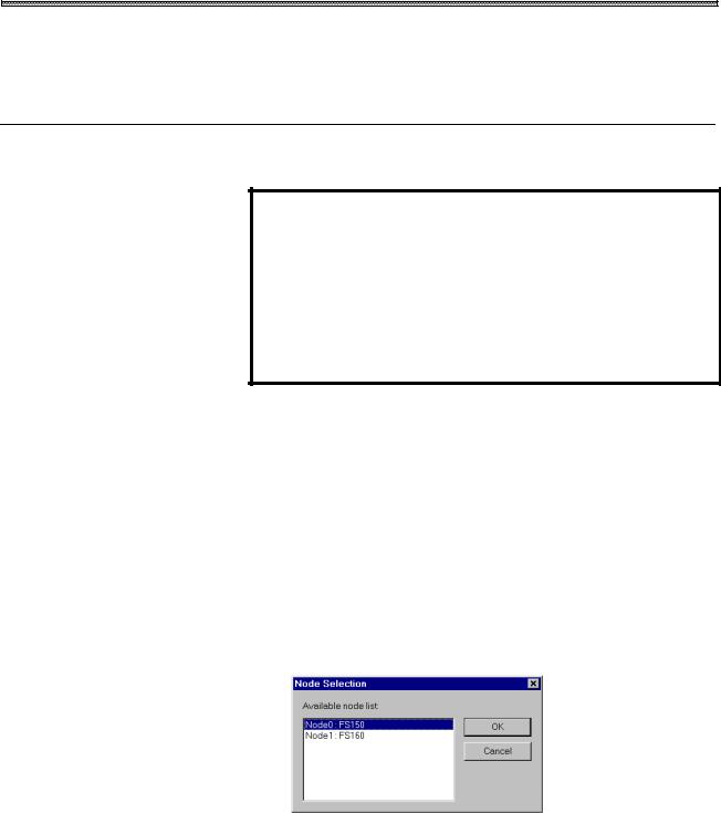
When High Speed Serial Bus multiconnection is being used, the node selection screen appears if a node number has not been specified for an argument for Basic Operation Package 1.
 For an explanation of how to specify the node number, see
Section 3.2, "Specifying a Node."
4. Select the CNC to be connected. Click the <OK> button.
-10-
Loading...