


 Loading...
FANUC Robot LR Mate 200iD
FANUC Robot ARC Mate 50iD
MECHANICAL UNIT
OPERATOR’S MANUAL
MAROT200D01121E REV. F
©2018 FANUC America Corporation
All Rights Reserved.
This publication contains proprietary information of FANUC America Corporation furnished for customer use only. No other uses are authorized without the express written permission of FANUC America Corporation.
FANUC America Corporation
3900 W. Hamlin Road
Rochester Hills, Michigan 48309–3253
B-83494EN/06

Copyrights and Trademarks
This new publication contains proprietary information of FANUC America Corporation furnished for customer use only. No other uses are authorized without the express written permission of FANUC America Corporation.
The descriptions and specifications contained in this manual were in effect at the time this manual was approved for printing. FANUC America Corporation, hereinafter referred to as FANUC, reserves the right to discontinue models at any time or to change specifications or design without notice and without incurring obligations.
FANUC manuals present descriptions, specifications, drawings, schematics, bills of material, parts, connections and/or procedures for installing, disassembling, connecting, operating and programming FANUC products and/or systems. Such systems consist of robots, extended axes, robot controllers, application software, the KAREL® programming language, INSIGHT® vision equipment, and special tools.
FANUC recommends that only persons who have been trained in one or more approved FANUC Training Course(s) be permitted to install, operate, use, perform procedures on, repair, and/or maintain FANUC products and/or systems and their respective components. Approved training necessitates that the courses selected be relevant to the type of system installed and application performed at the customer site.
 WARNING
This equipment generates, uses, and can radiate radiofrequency energy and if not installed and used in accordance with the instruction manual, may cause interference to radio communications. As temporarily permitted by regulation, it has not been tested for compliance with the limits for Class A computing devices pursuant to Subpart J and Part 15 of FCC Rules, which are designed to provide reasonable protection against such interference. Operation of the equipment in a residential area is likely to cause interference, in which case the user, at his own expense, will be required to take whatever measure may be required to correct the interference.

FANUC conducts courses on its systems and products on a regularly scheduled basis at the company's world headquarters in Rochester Hills, Michigan. For additional information contact
FANUC America Corporation Training Department
3900 W. Hamlin Road
Rochester Hills, Michigan 48309-3253 www.fanucamerica.com
For customer assistance, including Technical Support, Service, Parts & Part Repair, and Marketing Requests, contact the Customer Resource Center, 24 hours a day, at 888-FANUC-US (888-326-8287).
Send your comments and suggestions about this manual to: product.documentation@fanucamerica.com
Copyright © 2018 by FANUC America Corporation
All Rights Reserved
The information illustrated or contained herein is not to be
reproduced, copied, downloaded, translated into another language, published in any physical or electronic format, including internet, or transmitted in whole or in part in any way without the prior written consent of FANUC America Corporation.
AccuStat®, ArcTool®, iRVision®, KAREL®, PaintTool®, PalletTool®, SOCKETS®, SpotTool®, SpotWorks®, and TorchMate® are Registered Trademarks of FANUC.
FANUC reserves all proprietary rights, including but not
limited to trademark and trade name rights, in the following names:
AccuAir™, AccuCal™, AccuChop™, AccuFlow™, AccuPath™, AccuSeal™, ARC Mate™, ARC Mate Sr.™, ARC Mate System 1™, ARC Mate System 2™, ARC Mate System 3™, ARC Mate System 4™, ARC Mate System 5™, ARCWorks Pro™, AssistTool™, AutoNormal™, AutoTCP™, BellTool™, BODYWorks™, Cal Mate™, Cell Finder™,
Center Finder™, Clean Wall™, DualARM™, iRProgrammer™, LR Tool™, MIG Eye™, MotionParts™, MultiARM™, NoBots™, Paint
Stick™, PaintPro™, PaintTool 100™, PAINTWorks™, PAINTWorks II™, PAINTWorks III™, PalletMate™, PalletMate PC™,
PalletTool PC™, PayloadID™, RecipTool™, RemovalTool™, Robo Chop™, Robo Spray™, S-420i™, S-430i™, ShapeGen™, SoftFloat™, SOFT PARTS™, SpotTool+™, SR Mate™, SR
ShotTool™, SureWeld™, SYSTEM R-J2 Controller™, SYSTEM R-J3 Controller™, SYSTEM R-J3iB Controller™, SYSTEM R-J3iC Controller™, SYSTEM R-30iA Controller™, SYSTEM R-30iA Mate Controller™, SYSTEM R-30iB Controller™, SYSTEM R-30iB Mate Controller™, SYSTEM R-30iB Plus Controller™, SYSTEM R-30iB Mate Plus Controller™, TCP Mate™, TorchMate™, TripleARM™, TurboMove™, visLOC™, visPRO-3D™, visTRAC™, WebServer™, WebTP™, and YagTool™.
©FANUC CORPORATION 2018
•No part of this manual may be reproduced in any form.
•All specifications and designs are subject to change without notice.
Patents
One or more of the following U.S. patents might be related to the FANUC products described in this manual.
FANUC America Corporation Patent List
4,630,567 4,639,878 4,707,647 4,708,175 4,708,580 4,942,539 4,984,745
5,238,029 5,239,739 5,272,805 5,293,107 5,293,911 5,331,264 5,367,944
5,373,221 5,421,218 5,434,489 5,644,898 5,670,202 5,696,687 5,737,218
5,823,389 5,853,027 5,887,800 5,941,679 5,959,425 5,987,726 6,059,092
6,064,168 6,070,109 6,086,294 6,122,062 6,147,323 6,204,620 6,243,621
6,253,799 6,285,920 6,313,595 6,325,302 6,345,818 6,356,807 6,360,143
6,378,190 6,385,508 6,425,177 6,477,913 6,490,369 6,518,980 6,540,104
6,541,757 6,560,513 6,569,258 6,612,449 6,703,079 6,705,361 6,726,773
6,768,078 6,845,295 6,945,483 7,149,606 7,149,606 7,211,978 7,266,422
7,399,363
FANUC CORPORATION Patent List
4,571,694 4,626,756 4,700,118 4,706,001 4,728,872 4,732,526 4,742,207
4,835,362 4,894,596 4,899,095 4,920,248 4,931,617 4,934,504 4,956,594
4,967,125 4,969,109 4,970,370 4,970,448 4,979,127 5,004,968 5,006,035
5,008,834 5,063,281 5,066,847 5,066,902 5,093,552 5,107,716 5,111,019
5,130,515 5,136,223 5,151,608 5,170,109 5,189,351 5,267,483 5,274,360
5,292,066 5,300,868 5,304,906 5,313,563 5,319,443 5,325,467 5,327,057
5,329,469 5,333,242 5,337,148 5,371,452 5,375,480 5,418,441 5,432,316
5,440,213 5,442,155 5,444,612 5,449,875 5,451,850 5,461,478 5,463,297
5,467,003 5,471,312 5,479,078 5,485,389 5,485,552 5,486,679 5,489,758
5,493,192 5,504,766 5,511,007 5,520,062 5,528,013 5,532,924 5,548,194
5,552,687 5,558,196 5,561,742 5,570,187 5,570,190 5,572,103 5,581,167
5,582,750 5,587,635 5,600,759 5,608,299 5,608,618 5,624,588 5,630,955
5,637,969 5,639,204 5,641,415 5,650,078 5,658,121 5,668,628 5,687,295
5,691,615 5,698,121 5,708,342 5,715,375 5,719,479 5,727,132 5,742,138
5,742,144 5,748,854 5,749,058 5,760,560 5,773,950 5,783,922 5,799,135
5,812,408 5,841,257 5,845,053 5,872,894 5,887,122 5,911,892 5,912,540
5,920,678 5,937,143 5,980,082 5,983,744 5,987,591 5,988,850 6,023,044
6,032,086 6,040,554 6,059,169 6,088,628 6,097,169 6,114,824 6,124,693
6,140,788 6,141,863 6,157,155 6,160,324 6,163,124 6,177,650 6,180,898
6,181,096 6,188,194 6,208,105 6,212,444 6,219,583 6,226,181 6,236,011
6,236,896 6,250,174 6,278,902 6,279,413 6,285,921 6,298,283 6,321,139
6,324,443 6,328,523 6,330,493 6,340,875 6,356,671 6,377,869 6,382,012
6,384,371 6,396,030 6,414,711 6,424,883 6,431,018 6,434,448 6,445,979
6,459,958 6,463,358 6,484,067 6,486,629 6,507,165 6,654,666 6,665,588
6,680,461 6,696,810 6,728,417 6,763,284 6,772,493 6,845,296 6,853,881
6,888,089 6,898,486 6,917,837 6,928,337 6,965,091 6,970,802 7,038,165
7,069,808 7,084,900 7,092,791 7,133,747 7,143,100 7,149,602 7,131,848
7,161,321 7,171,041 7,174,234 7,173,213 7,177,722 7,177,439 7,181,294
7,181,313 7,280,687 7,283,661 7,291,806 7,299,713 7,315,650 7,324,873
7,328,083 7,330,777 7,333,879 7,355,725 7,359,817 7,373,220 7,376,488
7,386,367 7,464,623 7,447,615 7,445,260 7,474,939 7,486,816 7,495,192
7,501,778 7,502,504 7,508,155 7,512,459 7,525,273 7,526,121

Conventions
 WARNING
Information appearing under the "WARNING" caption concerns the protection of personnel. It is boxed and bolded to set it apart from the surrounding text.
 CAUTION
Information appearing under the "CAUTION" caption concerns the protection of equipment, software, and data. It is boxed and bolded to set it apart from the surrounding text.
Note Information appearing next to NOTE concerns related information or useful hints.

•Original Instructions
Thank you very much for purchasing FANUC Robot.
Before using the Robot, be sure to read the "FANUC Robot SAFETY HANDBOOK (B-80687EN)" and understand the content.
•No part of this manual may be reproduced in any form.
•The appearance and specifications of this product are subject to change without notice.
The products in this manual are controlled based on Japan's “Foreign Exchange and Foreign Trade Law". The export from Japan may be subject to an export license by the government of Japan. Further, re-export to another country may be subject to the license of the government of the country from where the product is re-exported. Furthermore, the product may also be controlled by re-export regulations of the United States government.
Should you wish to export or re-export these products, please contact FANUC for advice.
In this manual, we endeavor to include all pertinent matters. There are, however, a very large number of operations that must not or cannot be performed, and if the manual contained them all, it would be enormous in volume. It is, therefore, requested to assume that any operations that are not explicitly described as being possible are "not possible".

Safety
FANUC America Corporation is not and does not represent itself as an expert in safety systems, safety equipment, or the specific safety aspects of your company and/or its work force. It is the responsibility of the owner, employer, or user to take all necessary steps to guarantee the safety of all personnel in the workplace.
The appropriate level of safety for your application and installation can be best determined by safety system professionals. FANUC America Corporation therefore, recommends that each customer consult with such professionals in order to provide a workplace that allows for the safe application, use, and operation of FANUC America Corporation systems.
According to the industry standard ANSI/RIA R15-06, the owner or user is advised to consult the standards to ensure compliance with its requests for Robotics System design, usability, operation, maintenance, and service. Additionally, as the owner, employer, or user of a robotic system, it is your responsibility to arrange for the training of the operator of a robot system to recognize and respond to known hazards associated with your robotic system and to be aware of the recommended operating procedures for your particular application and robot installation.
Ensure that the robot being used is appropriate for the application. Robots used in classified (hazardous) locations must be certified for this use.
FANUC America Corporation therefore, recommends that all personnel who intend to operate, program, repair, or otherwise use the robotics system be trained in an approved FANUC America Corporation training course and become familiar with the proper operation of the system. Persons responsible for programming the system–including the design, implementation, and debugging of application programs–must be familiar with the recommended programming procedures for your application and robot installation.
The following guidelines are provided to emphasize the importance of safety in the workplace.
CONSIDERING SAFETY FOR YOUR ROBOT INSTALLATION
Safety is essential whenever robots are used. Keep in mind the following factors with regard to safety:
The safety of people and equipment
Use of safety enhancing devices
Techniques for safe teaching and manual operation of the robot(s)
Techniques for safe automatic operation of the robot(s)
Regular scheduled inspection of the robot and workcell
Proper maintenance of the robot
i

Safety
Keeping People Safe
The safety of people is always of primary importance in any situation. When applying safety measures to your robotic system, consider the following:
External devices
Robot(s)
Tooling
Workpiece
Using Safety Enhancing Devices
Always give appropriate attention to the work area that surrounds the robot. The safety of the work area can be enhanced by the installation of some or all of the following devices:
Safety fences, barriers, or chains
Light curtains
Interlocks
Pressure mats
Floor markings
Warning lights
Mechanical stops
EMERGENCY STOP buttons
DEADMAN switches
Setting Up a Safe Workcell
A safe workcell is essential to protect people and equipment. Observe the following guidelines to ensure that the workcell is set up safely. These suggestions are intended to supplement and not replace existing federal, state, and local laws, regulations, and guidelines that pertain to safety.
Sponsor your personnel for training in approved FANUC America Corporation training course(s) related to your application. Never permit untrained personnel to operate the robots.
Install a lockout device that uses an access code to prevent unauthorized persons from operating the robot.
Use anti–tie–down logic to prevent the operator from bypassing safety measures.
Arrange the workcell so the operator faces the workcell and can see what is going on inside the cell.
Clearly identify the work envelope of each robot in the system with floor markings, signs, and special barriers. The work envelope is the area defined by the maximum motion range of the robot, including any tooling attached to the wrist flange that extend this range.
ii

Safety
Position all controllers outside the robot work envelope.
Never rely on software or firmware based controllers as the primary safety element unless they comply with applicable current robot safety standards.
Mount an adequate number of EMERGENCY STOP buttons or switches within easy reach of the operator and at critical points inside and around the outside of the workcell.
Install flashing lights and/or audible warning devices that activate whenever the robot is operating, that is, whenever power is applied to the servo drive system. Audible warning devices shall exceed the ambient noise level at the end–use application.
Wherever possible, install safety fences to protect against unauthorized entry by personnel into the work envelope.
Install special guarding that prevents the operator from reaching into restricted areas of the work envelope.
Use interlocks.
Use presence or proximity sensing devices such as light curtains, mats, and capacitance and vision systems to enhance safety.
Periodically check the safety joints or safety clutches that can be optionally installed between the robot wrist flange and tooling. If the tooling strikes an object, these devices dislodge, remove power from the system, and help to minimize damage to the tooling and robot.
Make sure all external devices are properly filtered, grounded, shielded, and suppressed to prevent hazardous motion due to the effects of electro–magnetic interference (EMI), radio frequency interference (RFI), and electro–static discharge (ESD).
Make provisions for power lockout/tagout at the controller.
Eliminate pinch points. Pinch points are areas where personnel could get trapped between a moving robot and other equipment.
Provide enough room inside the workcell to permit personnel to teach the robot and perform maintenance safely.
Program the robot to load and unload material safely.
If high voltage electrostatics are present, be sure to provide appropriate interlocks, warning, and beacons.
If materials are being applied at dangerously high pressure, provide electrical interlocks for lockout of material flow and pressure.
Staying Safe While Teaching or Manually Operating the Robot
Advise all personnel who must teach the robot or otherwise manually operate the robot to observe the following rules:
Never wear watches, rings, neckties, scarves, or loose clothing that could get caught in moving machinery.
Know whether or not you are using an intrinsically safe teach pendant if you are working in a hazardous environment.
iii
Safety
Before teaching, visually inspect the robot and work envelope to make sure that no potentially hazardous conditions exist. The work envelope is the area defined by the maximum motion range of the robot. These include tooling attached to the wrist flange that extends this range.
The area near the robot must be clean and free of oil, water, or debris. Immediately report unsafe working conditions to the supervisor or safety department.
FANUC America Corporation recommends that no one enter the work envelope of a robot that is on, except for robot teaching operations. However, if you must enter the work envelope, be sure all safeguards are in place, check the teach pendant DEADMAN switch for proper operation, and place the robot in teach mode. Take the teach pendant with you, turn it on, and be prepared to release the DEADMAN switch. Only the person with the teach pendant should be in the work envelope.
 WARNING
Never bypass, strap, or otherwise deactivate a safety device, such as a limit switch, for any operational convenience. Deactivating a safety device is known to have resulted in serious injury and death.
Know the path that can be used to escape from a moving robot; make sure the escape path is never blocked.
Isolate the robot from all remote control signals that can cause motion while data is being taught.
Test any program being run for the first time in the following manner:
 WARNING
Stay outside the robot work envelope whenever a program is being run. Failure to do so can result in injury.
-Using a low motion speed, single step the program for at least one full cycle.
-Using a low motion speed, test run the program continuously for at least one full cycle.
-Using the programmed speed, test run the program continuously for at least one full cycle.
Make sure all personnel are outside the work envelope before running production.
Staying Safe During Automatic Operation
Advise all personnel who operate the robot during production to observe the following rules:
Make sure all safety provisions are present and active.
iv

Safety
Know the entire workcell area. The workcell includes the robot and its work envelope, plus the area occupied by all external devices and other equipment with which the robot interacts.
Understand the complete task the robot is programmed to perform before initiating automatic operation.
Make sure all personnel are outside the work envelope before operating the robot.
Never enter or allow others to enter the work envelope during automatic operation of the robot.
Know the location and status of all switches, sensors, and control signals that could cause the robot to move.
Know where the EMERGENCY STOP buttons are located on both the robot control and external control devices. Be prepared to press these buttons in an emergency.
Never assume that a program is complete if the robot is not moving. The robot could be waiting for an input signal that will permit it to continue its activity.
If the robot is running in a pattern, do not assume it will continue to run in the same pattern.
Never try to stop the robot, or break its motion, with your body. The only way to stop robot motion immediately is to press an EMERGENCY STOP button located on the controller panel, teach pendant, or emergency stop stations around the workcell.
Staying Safe During Inspection
When inspecting the robot, be sure to
Turn off power at the controller.
Lock out and tag out the power source at the controller according to the policies of your plant.
Turn off the compressed air source and relieve the air pressure.
If robot motion is not needed for inspecting the electrical circuits, press the EMERGENCY STOP button on the operator panel.
Never wear watches, rings, neckties, scarves, or loose clothing that could get caught in moving machinery.
If power is needed to check the robot motion or electrical circuits, be prepared to press the EMERGENCY STOP button, in an emergency.
Be aware that when you remove a servomotor or brake, the associated robot arm will fall if it is not supported or resting on a hard stop. Support the arm on a solid support before you release the brake.
Staying Safe During Maintenance
When performing maintenance on your robot system, observe the following rules:
Never enter the work envelope while the robot or a program is in operation.
Before entering the work envelope, visually inspect the workcell to make sure no potentially hazardous conditions exist.
v

Safety
Never wear watches, rings, neckties, scarves, or loose clothing that could get caught in moving machinery.
Consider all or any overlapping work envelopes of adjoining robots when standing in a work envelope.
Test the teach pendant for proper operation before entering the work envelope.
If it is necessary for you to enter the robot work envelope while power is turned on, you must be sure that you are in control of the robot. Be sure to take the teach pendant with you, press the DEADMAN switch, and turn the teach pendant on. Be prepared to release the DEADMAN switch to turn off servo power to the robot immediately.
Whenever possible, perform maintenance with the power turned off. Before you open the controller front panel or enter the work envelope, turn off and lock out the 3–phase power source at the controller.
Be aware that when you remove a servomotor or brake, the associated robot arm will fall if it is not supported or resting on a hard stop. Support the arm on a solid support before you release the brake.
 WARNING
Lethal voltage is present in the controller WHENEVER IT IS CONNECTED to a power source. Be extremely careful to avoid electrical shock. HIGH VOLTAGE IS PRESENT at the input side whenever the controller is connected to a power source. Turning the disconnect or circuit breaker to the OFF position removes power from the output side of the device only.
Release or block all stored energy. Before working on the pneumatic system, shut off the system air supply and purge the air lines.
Isolate the robot from all remote control signals. If maintenance must be done when the power is on, make sure the person inside the work envelope has sole control of the robot. The teach pendant must be held by this person.
Make sure personnel cannot get trapped between the moving robot and other equipment. Know the path that can be used to escape from a moving robot. Make sure the escape route is never blocked.
Use blocks, mechanical stops, and pins to prevent hazardous movement by the robot. Make sure that such devices do not create pinch points that could trap personnel.
 WARNING
Do not try to remove any mechanical component from the robot before thoroughly reading and understanding the procedures in the appropriate manual. Doing so can result in serious personal injury and component destruction.
vi

Safety
Be aware that when you remove a servomotor or brake, the associated robot arm will fall if it is not supported or resting on a hard stop. Support the arm on a solid support before you release the brake.
When replacing or installing components, make sure dirt and debris do not enter the system.
Use only specified parts for replacement. To avoid fires and damage to parts in the controller, never use nonspecified fuses.
Before restarting a robot, make sure no one is inside the work envelope; be sure that the robot and all external devices are operating normally.
KEEPING MACHINE TOOLS AND EXTERNAL DEVICES SAFE
Certain programming and mechanical measures are useful in keeping the machine tools and other external devices safe. Some of these measures are outlined below. Make sure you know all associated measures for safe use of such devices.
Programming Safety Precautions
Implement the following programming safety measures to prevent damage to machine tools and other external devices.
Back–check limit switches in the workcell to make sure they do not fail.
Implement ‘‘failure routines” in programs that will provide appropriate robot actions if an external device or another robot in the workcell fails.
Use handshaking protocol to synchronize robot and external device operations.
Program the robot to check the condition of all external devices during an operating cycle.
Mechanical Safety Precautions
Implement the following mechanical safety measures to prevent damage to machine tools and other external devices.
Make sure the workcell is clean and free of oil, water, and debris.
Use DCS (Dual Check Safety), software limits, limit switches, and mechanical hardstops to prevent undesired movement of the robot into the work area of machine tools and external devices.
vii

Safety
KEEPING THE ROBOT SAFE
Observe the following operating and programming guidelines to prevent damage to the robot.
Operating Safety Precautions
The following measures are designed to prevent damage to the robot during operation.
Use a low override speed to increase your control over the robot when jogging the robot.
Visualize the movement the robot will make before you press the jog keys on the teach pendant.
Make sure the work envelope is clean and free of oil, water, or debris.
Use circuit breakers to guard against electrical overload.
Programming Safety Precautions
The following safety measures are designed to prevent damage to the robot during programming:
Establish interference zones to prevent collisions when two or more robots share a work area.
Make sure that the program ends with the robot near or at the home position.
Be aware of signals or other operations that could trigger operation of tooling resulting in personal injury or equipment damage.
In dispensing applications, be aware of all safety guidelines with respect to the dispensing materials.
NOTE: Any deviation from the methods and safety practices described in this manual must conform to the approved standards of your company. If you have questions, see your supervisor.
ADDITIONAL SAFETY CONSIDERATIONS FOR PAINT ROBOT INSTALLATIONS
Process technicians are sometimes required to enter the paint booth, for example, during daily or routine calibration or while teaching new paths to a robot. Maintenance personnel also must work inside the paint booth periodically.
Whenever personnel are working inside the paint booth, ventilation equipment must be used. Instruction on the proper use of ventilating equipment usually is provided by the paint shop supervisor.
viii

Safety
Although paint booth hazards have been minimized, potential dangers still exist. Therefore, today’s highly automated paint booth requires that process and maintenance personnel have full awareness of the system and its capabilities. They must understand the interaction that occurs between the vehicle moving along the conveyor and the robot(s), hood/deck and door opening devices, and high–voltage electrostatic tools.
 CAUTION
Ensure that all ground cables remain connected. Never operate the paint robot with ground provisions disconnected. Otherwise, you could injure personnel or damage equipment.
Paint robots are operated in three modes:
Teach or manual mode
Automatic mode, including automatic and exercise operation
Diagnostic mode
During both teach and automatic modes, the robots in the paint booth will follow a predetermined pattern of movements. In teach mode, the process technician teaches (programs) paint paths using the teach pendant.
In automatic mode, robot operation is initiated at the System Operator Console (SOC) or Manual Control Panel (MCP), if available, and can be monitored from outside the paint booth. All personnel must remain outside of the booth or in a designated safe area within the booth whenever automatic mode is initiated at the SOC or MCP.
In automatic mode, the robots will execute the path movements they were taught during teach mode, but generally at production speeds.
When process and maintenance personnel run diagnostic routines that require them to remain in the paint booth, they must stay in a designated safe area.
Paint System Safety Features
Process technicians and maintenance personnel must become totally familiar with the equipment and its capabilities. To minimize the risk of injury when working near robots and related equipment, personnel must comply strictly with the procedures in the manuals.
This section provides information about the safety features that are included in the paint system and also explains the way the robot interacts with other equipment in the system.
The paint system includes the following safety features:
Most paint booths have red warning beacons that illuminate when the robots are armed and ready to paint. Your booth might have other kinds of indicators. Learn what these are.
ix

Safety
Some paint booths have a blue beacon that, when illuminated, indicates that the electrostatic devices are enabled. Your booth might have other kinds of indicators. Learn what these are.
EMERGENCY STOP buttons are located on the robot controller and teach pendant. Become familiar with the locations of all E–STOP buttons.
An intrinsically safe teach pendant is used when teaching in hazardous paint atmospheres.
A DEADMAN switch is located on each teach pendant. When this switch is held in, and the teach pendant is on, power is applied to the robot servo system. If the engaged DEADMAN switch is released or pressed harder during robot operation, power is removed from the servo system, all axis brakes are applied, and the robot comes to an EMERGENCY STOP. Safety interlocks within the system might also E–STOP other robots.
 WARNING
An EMERGENCY STOP will occur if the DEADMAN switch is released on a bypassed robot.
Overtravel by robot axes is prevented by software limits. All of the major and minor axes are governed by software limits. DCS (Dual Check Safety), limit switches and hardstops also limit travel by the major axes.
EMERGENCY STOP limit switches and photoelectric eyes might be part of your system. Limit switches, located on the entrance/exit doors of each booth, will EMERGENCY STOP all equipment in the booth if a door is opened while the system is operating in automatic or manual mode. For some systems, signals to these switches are inactive when the switch on the SOC is in teach mode.
When present, photoelectric eyes are sometimes used to monitor unauthorized intrusion through the entrance/exit silhouette openings.
System status is monitored by computer. Severe conditions result in automatic system shutdown.
Staying Safe While Operating the Paint Robot
When you work in or near the paint booth, observe the following rules, in addition to all rules for safe operation that apply to all robot systems.
 WARNING
Observe all safety rules and guidelines to avoid injury.
x

Safety
 WARNING
Never bypass, strap, or otherwise deactivate a safety device, such as a limit switch, for any operational convenience. Deactivating a safety device is known to have resulted in serious injury and death.
 WARNING
Enclosures shall not be opened unless the area is known to be nonhazardous or all power has been removed from devices within the enclosure. Power shall not be restored after the enclosure has been opened until all combustible dusts have been removed from the interior of the enclosure and the enclosure purged. Refer to the Purge chapter for the required purge time.
Know the work area of the entire paint station (workcell).
Know the work envelope of the robot and hood/deck and door opening devices.
Be aware of overlapping work envelopes of adjacent robots.
Know where all red, mushroom–shaped EMERGENCY STOP buttons are located.
Know the location and status of all switches, sensors, and/or control signals that might cause the robot, conveyor, and opening devices to move.
Make sure that the work area near the robot is clean and free of water, oil, and debris. Report unsafe conditions to your supervisor.
Become familiar with the complete task the robot will perform BEFORE starting automatic mode.
Make sure all personnel are outside the paint booth before you turn on power to the robot servo system.
Never enter the work envelope or paint booth before you turn off power to the robot servo system.
Never enter the work envelope during automatic operation unless a safe area has been designated.
Never wear watches, rings, neckties, scarves, or loose clothing that could get caught in moving machinery.
Remove all metallic objects, such as rings, watches, and belts, before entering a booth when the electrostatic devices are enabled.
Stay out of areas where you might get trapped between a moving robot, conveyor, or opening device and another object.
Be aware of signals and/or operations that could result in the triggering of guns or bells.
Be aware of all safety precautions when dispensing of paint is required.
Follow the procedures described in this manual.
xi

Safety
Special Precautions for Combustible Dusts (Powder Paint)
When the robot is used in a location where combustible dusts are found, such as the application of powder paint, the following special precautions are required to insure that there are no combustible dusts inside the robot.
Purge maintenance air should be maintained at all times, even when the robot power is off. This will insure that dust can not enter the robot.
A purge cycle will not remove accumulated dusts. Therefore, if the robot is exposed to dust when maintenance air is not present, it will be necessary to remove the covers and clean out any accumulated dust. Do not energize the robot until you have performed the following steps.
1.Before covers are removed, the exterior of the robot should be cleaned to remove accumulated dust.
2.When cleaning and removing accumulated dust, either on the outside or inside of the robot, be sure to use methods appropriate for the type of dust that exists. Usually lint free rags dampened with water are acceptable. Do not use a vacuum cleaner to remove dust as it can generate static electricity and cause an explosion unless special precautions are taken.
3.Thoroughly clean the interior of the robot with a lint free rag to remove any accumulated dust.
4.When the dust has been removed, the covers must be replaced immediately.
5.Immediately after the covers are replaced, run a complete purge cycle. The robot can now be energized.
Staying Safe While Operating Paint Application Equipment
When you work with paint application equipment, observe the following rules, in addition to all rules for safe operation that apply to all robot systems.
 WARNING
When working with electrostatic paint equipment, follow all national and local codes as well as all safety guidelines within your organization. Also reference the following standards: NFPA 33 Standards for Spray Application Using Flammable or Combustible Materials, and NFPA 70 National Electrical Code.
Grounding: All electrically conductive objects in the spray area must be grounded. This includes the spray booth, robots, conveyors, workstations, part carriers, hooks, paint pressure pots, as well as solvent containers. Grounding is defined as the object or objects shall be electrically connected to ground with a resistance of not more than 1 megohms.
High Voltage: High voltage should only be on during actual spray operations. Voltage should be off when the painting process is completed. Never leave high voltage on during a cap cleaning process.
Avoid any accumulation of combustible vapors or coating matter.
Follow all manufacturer recommended cleaning procedures.
Make sure all interlocks are operational.
xii

Safety
No smoking.
Post all warning signs regarding the electrostatic equipment and operation of electrostatic equipment according to NFPA 33 Standard for Spray Application Using Flammable or Combustible Material.
Disable all air and paint pressure to bell.
Verify that the lines are not under pressure.
Staying Safe During Maintenance
When you perform maintenance on the painter system, observe the following rules, and all other maintenance safety rules that apply to all robot installations. Only qualified, trained service or maintenance personnel should perform repair work on a robot.
Paint robots operate in a potentially explosive environment. Use caution when working with electric tools.
When a maintenance technician is repairing or adjusting a robot, the work area is under the control of that technician. All personnel not participating in the maintenance must stay out of the area.
For some maintenance procedures, station a second person at the control panel within reach of the EMERGENCY STOP button. This person must understand the robot and associated potential hazards.
Be sure all covers and inspection plates are in good repair and in place.
Always return the robot to the ‘‘home’’ position before you disarm it.
Never use machine power to aid in removing any component from the robot.
During robot operations, be aware of the robot’s movements. Excess vibration, unusual sounds, and so forth, can alert you to potential problems.
Whenever possible, turn off the main electrical disconnect before you clean the robot.
When using vinyl resin observe the following:
-Wear eye protection and protective gloves during application and removal.
-Adequate ventilation is required. Overexposure could cause drowsiness or skin and eye irritation.
-If there is contact with the skin, wash with water.
-Follow the Original Equipment Manufacturer’s Material Safety Data Sheets.
When using paint remover observe the following:
-Eye protection, protective rubber gloves, boots, and apron are required during booth cleaning.
-Adequate ventilation is required. Overexposure could cause drowsiness.
-If there is contact with the skin or eyes, rinse with water for at least 15 minutes. Then seek medical attention as soon as possible.
-Follow the Original Equipment Manufacturer’s Material Safety Data Sheets.
xiii

B-83494EN/06 |
SAFETY PRECAUTIONS |
SAFETY PRECAUTIONS
This chapter must be read before using the robot.
For detailed functions of the robot operation, read the relevant operator's manual to understand fully its specification.
For the safety of the operator and the system, follow all safety precautions when operating a robot and its peripheral equipment installed in a work cell.
For safe use of FANUC robots, you must read and follow the instructions in “FANUC Robot SAFETY HANDBOOK (B-80687EN)”.
1 DEFINITION OF USER
The personnel can be classified as follows.
Operator:
•Turns the robot controller power on/off
•Starts the robot program from operator panel
Programmer or Teaching operator.
•Operates the robot
•Teaches the robot inside the safety fence
Maintenance engineer:
•Operates the robot
•Teaches the robot inside the safety fence
•Maintenance (repair, adjustment, replacement)
-Operator is not allowed to work in the safety fence.
-Programmer and maintenance engineer is allowed to work in the safety fence. Works carried out in the safety fence include transportation, installation, teaching, adjustment, and maintenance.
-To work inside the safety fence, the person must be trained on proper robot operation.
s-1

SAFETY PRECAUTIONS |
B-83494EN/06 |
Table 1 lists the work outside the safety fence. In this table, the symbol “{” means the work allowed to be carried out by the worker.
Table 1 List of work outside the fence |
|
||
|
Operator |
Programmer or |
Maintenance |
|
Teaching operator |
engineer |
|
|
|
||
Turn power ON/OFF to Robot controller |
{ |
{ |
{ |
Select operating mode (AUTO, T1, T2) |
|
{ |
{ |
Select remote/local mode |
|
{ |
{ |
Select robot program with teach pendant |
|
{ |
{ |
Select robot program with external device |
|
{ |
{ |
Start robot program with operator’s panel |
{ |
{ |
{ |
Start robot program with teach pendant |
|
{ |
{ |
Reset alarm with operator’s panel |
|
{ |
{ |
Reset alarm with teach pendant |
|
{ |
{ |
Set data on teach pendant |
|
{ |
|
Teaching with teach pendant |
|
{ |
|
Emergency stop with operator’s panel |
{ |
{ |
{ |
Emergency stop with teach pendant |
{ |
{ |
{ |
Maintain for operator’s panel |
|
{ |
|
Maintain for teach pendant |
|
|
{ |
In the robot operating, programming and maintenance, the operator, programmer, teaching operator and maintenance engineer take care of their safety using at least the following safety protectors.
•Use clothes, uniform, overall adequate for the work
•Safety shoes
•Helmet
2 DEFINITION OF SAFETY NOTATIONS
To ensure the safety of users and prevent damage to the machine, this manual indicates each precaution on safety with "WARNING" or "CAUTION" according to its severity. Supplementary information is indicated by "NOTE". Read the contents of each "WARNING", "CAUTION" and "NOTE" before using the robot.
Symbol |
Definitions |
|
WARNING |
Used if hazard resulting in the death or serious injury of the user will be expected to occur |
|
if he or she fails to follow the approved procedure. |
||
|
||
CAUTION |
Used if a hazard resulting in the minor or moderate injury of the user, or equipment |
|
damage may be expected to occur if he or she fails to follow the approved procedure. |
||
|
||
NOTE |
Used if a supplementary explanation not related to any of WARNING and CAUTION is to |
|
be indicated. |
||
|
•Check this manual thoroughly, and keep it handy for the future reference.
s-2

B-83494EN/06 |
SAFETY PRECAUTIONS |
3 PROCEDURE TO MOVE ARM WITHOUT DRIVE POWER IN EMERGENCY OR ABNORMAL SITUATIONS
Please drop the power supply of the robot control system at once when the worker is placed by the robot by any chance or it is confined, push the robot arm directly, change posture, and liberate the worker.
4 WARNING & CAUTION LABEL
(1)Transportation label
(except 7C/7LC) |
(7C/7LC) |
|
Fig. 4 (a) Transportation label |
Description
When transporting the robot, observe the instructions indicated on this label.
1)Use a crane having a load capacity of 100 kg or greater.
2)Use at least four slings each having a load capacity of 100 kg or greater.
3)Use at least four shackles and eyebolts each having an allowable load of 784 N (80 kgf) or greater.
s-3

SAFETY PRECAUTIONS |
B-83494EN/06 |
(2) Greasing label
(if greasing kit A05B-1142-K021, A05B-1142-K023 is specified)
2.5mm, |
|
1ml |
|
|
|
|
|
(Except 7C/7L) |
(7C/7LC) |
Fig. 4 (b) Greasing label |
|
Description
When using a grease kit, observe the instructions indicated on this label.
1)Before filling the cylinder with grease from tube, squeeze the tube to make the grease in it soft.
2)Pushing in the plunger by 2.5 mm causes a grease of 1 ml to be pushed out.
(3)Operation space and payload label
The following label is added if the CE specification is requested.
(Except 7H) |
(7H) |
Fig. 4 (c) Operation space and payload label
s-4

B-83494EN/06 |
PREFACE |
PREFACE
This manual explains maintenance procedures for the following mechanical units:
Model name |
|
Mechanical unit |
Maximum load |
Remarks |
|
specification No. |
|||
|
|
|
|
|
FANUC Robot LR Mate 200iD |
A05B-1142-B201 |
|
|
|
FANUC Robot LR Mate 200iD/7H |
A05B-1142-B211 |
|
5-axes type |
|
FANUC Robot LR Mate 200iD/7C |
A05B-1142-B221 |
|
Clean type |
|
FANUC Robot LR Mate 200iD/7WP |
A05B-1142-B231 |
7kg |
For washing |
|
FANUC Robot ARC Mate 50iD |
A05B-1142-B251 |
|
||
|
|
|||
FANUC Robot LR Mate 200iD/7L |
A05B-1142-B301 |
|
Long arm type |
|
FANUC Robot LR Mate 200iD/7LC |
A05B-1142-B321 |
|
Long arm, clean type |
|
FANUC Robot ARC Mate 50iD/7L |
A05B-1142-B351 |
|
Long arm type |
|
|
|
|
|
|
NOTE |
|
|
|
|
The following abbreviations are used herein. |
|
|
||
STANDARD |
: LR Mate 200iD, ARC Mate 50iD |
|
||
7H |
: LR Mate 200iD/7H |
|
|
|
7C |
: LR Mate 200iD/7C |
|
|
|
7WP |
: LR Mate 200iD/7WP |
|
|
|
7L |
: LR Mate 200iD/7L, ARC Mate 50iD/7L |
|
||
7LC |
: LR Mate 200iD/7LC |
|
|
|
p-1
PREFACE |
B-83494EN/06 |
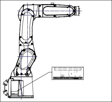
The label stating the mechanical unit specification number is affixed in the position shown below. Before reading this manual, verify the specification number of the mechanical unit.
(1)
TYPE 
 NO.
NO. 
 DATE
DATE 
|
|
( |
2) |
|
|
|
|
|
|
|
|
|
|
|
|
|
|
|
|
|
|||
|
|
|
|
|
|
|
WEIGHT |
||||
(3) |
|
|
|
|
|
||||||
|
|
|
|
|
|
|
|
|
|
|
kg |
(4) |
|
|
|
(5) |
|
||||||
|
|
|
|
|
|
|
|
|
|
|
|
Position of label indicating mechanical unit specification number
TABLE 1
|
(1) |
(2) |
(3) |
(4) |
(5) |
|
|
|
|
|
|
WEIGHT kg |
|
CONTENTS |
Model name |
TYPE |
No. |
DATE |
(Without |
|
|
|
|
|
|
controller) |
|
|
FANUC Robot |
A05B-1142-B201 |
|
|
25 |
|
|
LR Mate 200iD |
|
|
|||
|
|
|
|
|
||
|
FANUC Robot |
A05B-1142-B211 |
|
|
24 |
|
|
LR Mate 200iD/7H |
|
|
|||
|
|
|
|
|
||
|
FANUC Robot |
A05B-1142-B221 |
|
|
25 |
|
|
LR Mate 200iD/7C |
|
|
|||
|
|
|
PRODUCTION |
|
||
|
FANUC Robot |
A05B-1142-B231 |
SERIAL NO. IS |
25 |
||
LETTERS |
LR Mate 200iD/7WP |
YEAR AND |
||||
|
|
|||||
|
|
PRINTED |
MONTH ARE |
|
||
FANUC Robot |
A05B-1142-B251 |
25 |
||||
|
||||||
|
ARC Mate 50iD |
|
PRINTED |
|||
|
|
|
|
|||
|
FANUC Robot |
A05B-1142-B301 |
|
|
27 |
|
|
LR Mate 200iD/7L |
|
|
|||
|
|
|
|
|
||
|
FANUC Robot |
A05B-1142-B321 |
|
|
27 |
|
|
LR Mate 200iD/7LC |
|
|
|||
|
|
|
|
|
||
|
FANUC Robot |
A05B-1142-B351 |
|
|
27 |
|
|
ARC Mate 50iD/7L |
|
|
|||
|
|
|
|
|
p-2
B-83494EN/06 |
PREFACE |
RELATED MANUALS
For the FANUC Robot series, the following manuals are available:
SAFETY HANDBOOK B-80687EN |
Intended readers : |
|
All persons who use the FANUC Robot and system |
Operator, system designer |
|
designer must read and understand |
Topics : |
|
thoroughly this handbook |
Safety items for robot system design, operation, |
|
|
|
maintenance |
R-30iB Mate |
OPERATOR’S MANUAL |
Intended readers : |
R-30iB Mate Plus |
Basic Operation |
Operator, programmer, maintenance engineer, system |
controller |
B-83284EN |
designer |
|
Alarm Code List |
Topics : |
|
B-83284EN-1 |
Robot functions, operations, programming, setup, |
|
Optional Function |
interfaces, alarms |
|
B-83284EN-2 |
Use : |
|
|
Robot operation, teaching, system design |
|
MAINTENANCE MANUAL |
Intended readers : |
|
Standard : B-83525EN |
Maintenance engineer, system designer |
|
Open Air : B-83555EN |
Topics : |
|
|
Installation, start-up, connection, maintenance |
|
|
Use : |
|
|
Installation, start-up, connection, maintenance |
This manual uses following terms. |
|
|
|
|
|
|
Name |
Terms in this manual |
Connection cable between robot and controller |
Robot connection cable |
|
Robot mechanical unit |
Mechanical unit |
|
p-3
|
B-83494EN/06 |
|
TABLE OF CONTENTS |
|||
|
TABLE OF CONTENTS |
|
|
|||
|
SAFETY PRECAUTIONS............................................................................ |
s-1 |
||||
|
PREFACE |
.................................................................................................... |
|
p-1 |
||
|
1 |
TRANSPORTATION AND INSTALLATION ........................................... |
1 |
|
||
|
|
1.1 |
TRANSPORTATION...................................................................................... |
1 |
|
|
|
|
1.2 |
INSTALLATION ............................................................................................. |
6 |
|
|
|
|
|
1.2.1 Angle of Mounting Surface Setting.......................................................................... |
9 |
|
|
|
|
1.3 |
MAINTENANCE AREA................................................................................ |
11 |
|
|
|
|
1.4 |
INSTALLATION CONDITIONS.................................................................... |
11 |
|
|
|
2 CONNECTION WITH THE CONTROLLER .......................................... |
12 |
|
|||
|
|
2.1 |
CONNECTION WITH THE CONTROLLER................................................. |
12 |
|
|
|
3 |
BASIC SPECIFICATIONS..................................................................... |
14 |
|
||
|
|
3.1 |
ROBOT CONFIGURATION......................................................................... |
14 |
|
|
|
|
|
3.1.1 Note of Severe Dust /Liquid Specification............................................................. |
18 |
|
|
|
|
|
3.1.2 Cautions in Selecting the 7WP............................................................................... |
18 |
|
|
|
|
|
3.1.3 |
Cautions for 7C/7LC .............................................................................................. |
20 |
|
|
|
|
3.1.4 |
IP69K (option)........................................................................................................ |
20 |
|
|
|
3.2 |
MECHANICAL UNIT OPERATION AREA AND INTERFERENCE AREA ... |
21 |
|
|
|
|
3.3 |
ZERO POINT POSITION AND MOTION LIMIT........................................... |
23 |
|
|
|
|
3.4 |
WRIST LOAD CONDITIONS....................................................................... |
29 |
|
|
|
|
3.5 |
LOAD CONDITION ON EQUIPMENT MOUNTING FACE .......................... |
33 |
|
|
|
|
3.6 |
OPERATING AREA FOR INCLINATION INSTALLATION .......................... |
34 |
|
|
|
4 EQUIPMENT INSTALLATION TO THE ROBOT .................................. |
36 |
|
|||
|
|
4.1 |
END EFFECTOR INSTALLATION TO WRIST............................................ |
36 |
|
|
|
|
4.2 |
EQUIPMENT MOUNTING FACE ................................................................ |
36 |
|
|
|
|
4.3 |
LOAD SETTING .......................................................................................... |
38 |
|
|
|
|
4.4 |
HIGH INERTIA MODE (OPTION) (LR Mate 200iD/7H)............................... |
40 |
|
|
|
5 PIPING AND WIRING TO THE END EFFECTOR................................. |
41 |
|
|||
|
|
5.1 |
AIR SUPPLY (OPTION) .............................................................................. |
42 |
|
|
|
|
5.2 |
INSTALLING THE AIR PURGE KIT ............................................................ |
47 |
|
|
|
|
5.3 |
INTERFACE FOR OPTION CABLE ............................................................ |
51 |
|
|
|
6 |
AXIS LIMIT SETUP ............................................................................... |
54 |
|
||
|
|
6.1 |
SOFTWARE SETTING CHANGE AXIS LIMIT BY DCS (OPTION) ............. |
54 |
|
|
|
7 |
CHECKS AND MAINTENANCE ........................................................... |
58 |
|
||
|
|
7.1 |
CHECKS AND MAINTENANCE .................................................................. |
58 |
|
|
|
|
|
7.1.1 |
Daily Checks .......................................................................................................... |
58 |
|
|
|
|
7.1.2 Periodic Check and Maintenance ........................................................................... |
59 |
|
|
c-1
Loading...